abs JAGUAR X308 1998 2.G Service Manual
[x] Cancel search | Manufacturer: JAGUAR, Model Year: 1998, Model line: X308, Model: JAGUAR X308 1998 2.GPages: 2490, PDF Size: 69.81 MB
Page 202 of 2490
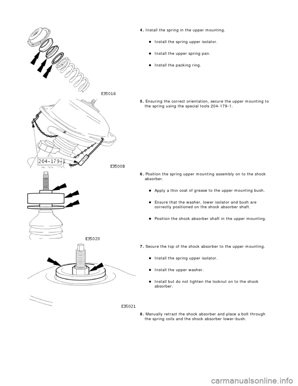
4. Install the spri
ng in
the upper mounting.
Install the spri
ng upper isolator.
Install
the up
per spring pan.
Inst
al
l the packing ring.
5. Ensuri ng the correct orientati
on,
secure the upper mounting to
the spring using the special tools 204-179-1.
6. Position the spri ng
upper mounting assembly on to the shock
absorber.
Apply a th in
coat of grease to the upper mounting bush.
E
n
sure that the washer, lo
wer isolator and bush are
correctly positioned on the shock absorber shaft.
Po si
tion the shock absorber shaft in the upper mounting.
7. Sec
ure the top of the shock ab
sorber to the upper mounting.
Install the spri
ng upper isolator.
Inst
al
l the upper washer.
In
s
tall but do not tighten the locknut on to the shock
absorber.
8. Manually retract the shock abso rber and place a bolt through
the spring coils and the sh ock absorber lower-bush.
Page 203 of 2490
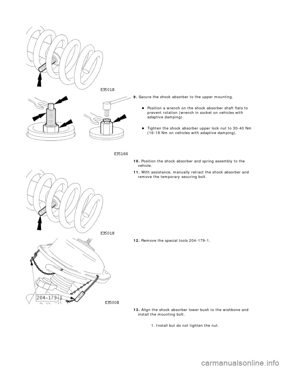
9. Se
cure the shock absorber
to the upper mounting.
Posi
tion a wrench on the shock absorber shaft flats to
prevent rotation (wrench in socket on vehicles with
adaptive damping).
Tigh
ten the shock absorber upper lock nut to 30-40 Nm
(16-18 Nm on vehicles with adaptive damping).
10. Position the shock absorber and spring assembly to the
vehicle.
11
.
With assistance, manually re tract the shock absorber and
remove the temporary securing bolt.
12
.
Remove the special tools 204-179-1.
13. Align the shock absorber lower bush to the wishbone and
install the mounting bolt.
1. Install but do not tighten the nut.
Page 204 of 2490
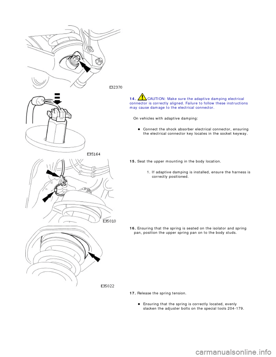
14. CAUTI
ON: Make sure the adaptive damping electrical
connector is correctly aligned. Failu re to follow these instructions
may cause damage to the electrical connector.
On vehicles with adaptive damping:
Conne ct
the shock absorber elec
trical connector, ensuring
the electrical connector key locates in the socket keyway.
15 . Seat
the upper mounting in the body location.
1. If adaptive damping is installed, ensure the harness is
correctly positioned.
16 . Ensuri
ng that the spri
ng is seated on the isolator and spring
pan, position the u pper spring pan on to the body studs.
17. Release the spring tension.
Ensuring that the spri
ng is
correctly located, evenly
slacken the adjuster bolts on the special tools 204-179.
Page 226 of 2490
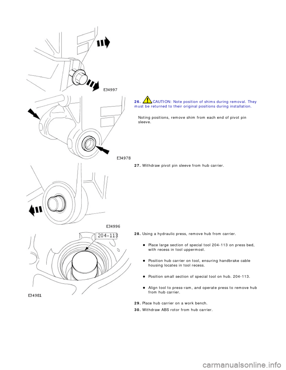
26. CAUTI
ON: Note position of
shims during removal. They
must be returned to their original positions during installation.
Noting positions, remove shim from each end of pivot pin
sleeve.
27 . W
ithdraw pivot pin sleeve from hub carrier.
28 .
Using a h
ydraulic press,
remove hub from carrier.
Plac
e large section of special tool 204-113 on press bed,
with recess in t ool uppermost.
Positi
on hub carrier on tool
, ensuring handbrake cable
housing locates in tool recess.
Posit i
on small section of special tool on hub. 204-113.
Align to
ol to press-r
am, and
operate press to remove hub
from hub carrier.
29. Place hub carrier on a work bench.
30. Withdraw ABS rotor from hub carrier.
Page 229 of 2490
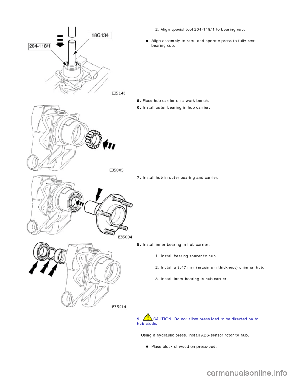
2
. Align special tool 204-118/1 to bearing cup.
Al
ign assembly to ram, and
operate press to fully seat
bearing cup.
5. Place hub carrier on a work bench.
6. Install outer bearing in hu
b carrier.
7. Inst
all hub in outer
bearing and carrier.
8. Inst
all inner bearing in hub carrier.
1. Install bearing spacer to hub.
2. Install a 3.47 mm (maximum thickness) shim on hub.
3. Install inner bearing in hub carrier.
9. CAUTION: Do not allow press load to be directed on to
hub studs.
Using a hydraulic press, install ABS-sensor rotor to hub.
Pl
ace block of wood on press-bed.
Page 230 of 2490
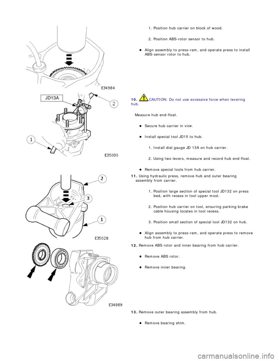
1.
Position hub carrier on block of wood.
2. Position ABS-rotor sensor to hub.
Ali g
n assembly to press-ram, and operate press to install
ABS-sensor rotor to hub.
10 . CAUTI
ON: Do not use excessive force when levering
hub.
Measure hub end-float.
Secure hub carri er in vi
ce.
Inst
al
l special tool JD15 to hub.
1. Install dial gauge JD 13A on hub carrier.
2. Using two levers, measure and record hub end-float.
R e
move special tools from hub carrier.
11
. Using h
ydraulic pr
ess, remove hub and outer bearing
assembly from carrier.
1. Position large section of special tool JD132 on press bed, with recess in tool upper most.
2. Position hub carrier on tool, ensuring parking brake cable housing locates in tool recess.
3. Position small section of special tool JD132 on hub.
Alig
n assembly to press-ram, and operate press to remove
hub from hub carrier.
12 . R
emove ABS rotor and inner bearing from hub carrier.
R
e
move ABS rotor.
R
e
move inner bearing.
13. Remove outer bearing assembly from hub.
Remove bearing shim.
Page 232 of 2490
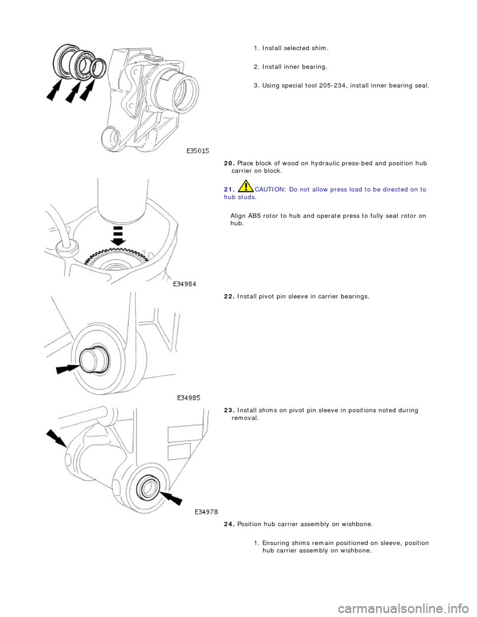
1. Ins
tall selected shim.
2. Install inner bearing.
3. Using special tool 205-234, install inner bearing seal.
20. Place block of wood on hydrau lic press-bed and position hub
carrier on block.
21 . CAUTI
ON: Do not allow press load to be directed on to
hub studs.
Align ABS rotor to hub and operat e press to fully seat rotor on
hub.
22 . Install piv
ot pin sleeve in carrier bearings.
23 . Inst
all shims on pivot pin slee
ve in positions noted during
removal.
24. Position hub carrier as sembly on wishbone.
1. Ensuring shims remain posi tioned on sleeve, position
hub carrier assembly on wishbone.
Page 242 of 2490
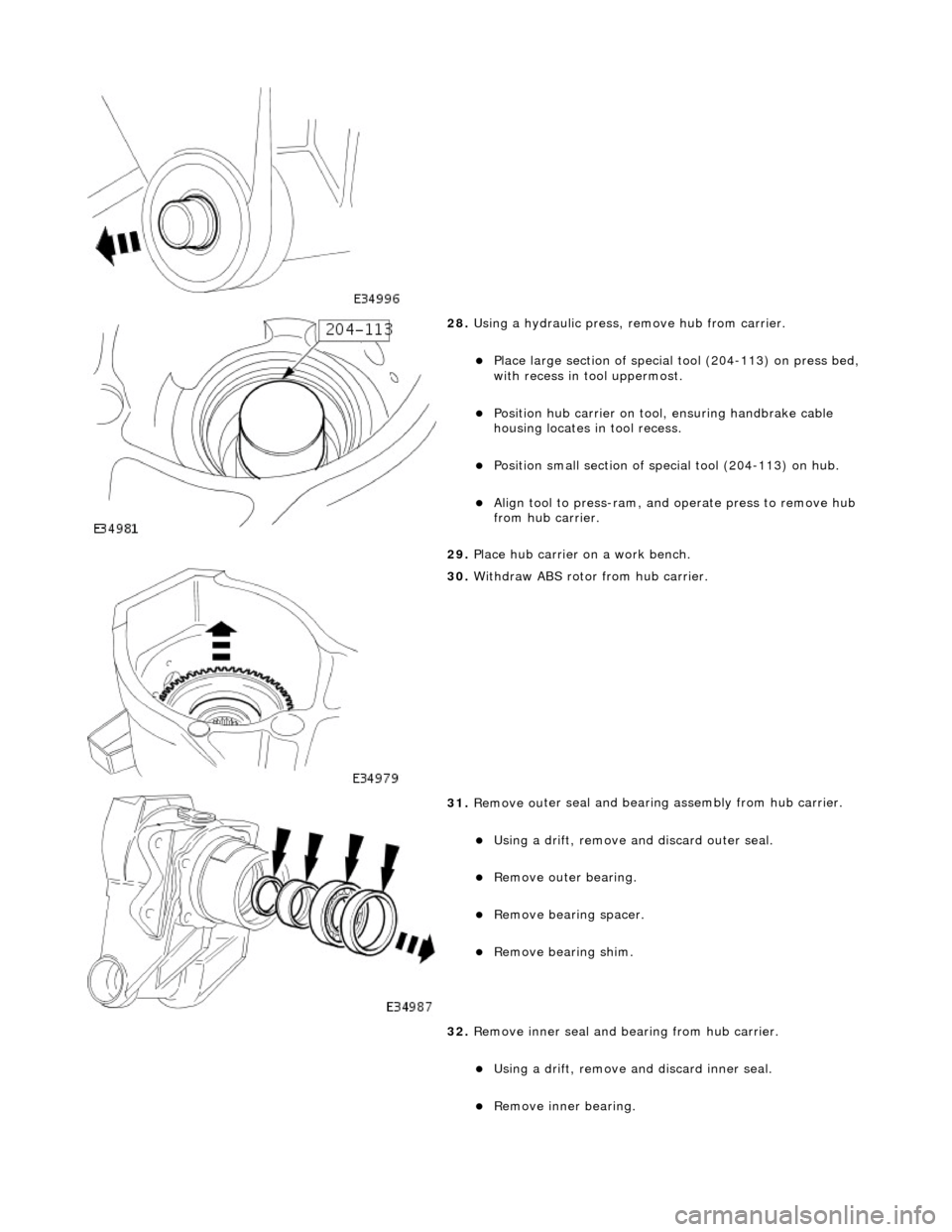
28. Using a h
ydraulic press,
remove hub from carrier.
Pla
ce large section of special tool (204-113) on press bed,
with recess in t ool uppermost.
Positi
on hub carrier on tool
, ensuring handbrake cable
housing locates in tool recess.
P o
sition small section of spec
ial tool (204-113) on hub.
Align tool to press-r
am, and
operate press to remove hub
from hub carrier.
29. Place hub carrier on a work bench.
30 . W
ithdraw ABS rotor from hub carrier.
31 . Remove ou
ter seal and bearin
g assembly from hub carrier.
Using a drift, re
move an
d discard outer seal.
Remove ou ter bearin
g.
Re
mo
ve bearin
g spacer.
Remove bearin g shim.
32
.
Remove inner seal and bearing from hub carrier.
Using a drift, re
move and discard inner seal.
Re
move inner bearing.
Page 244 of 2490
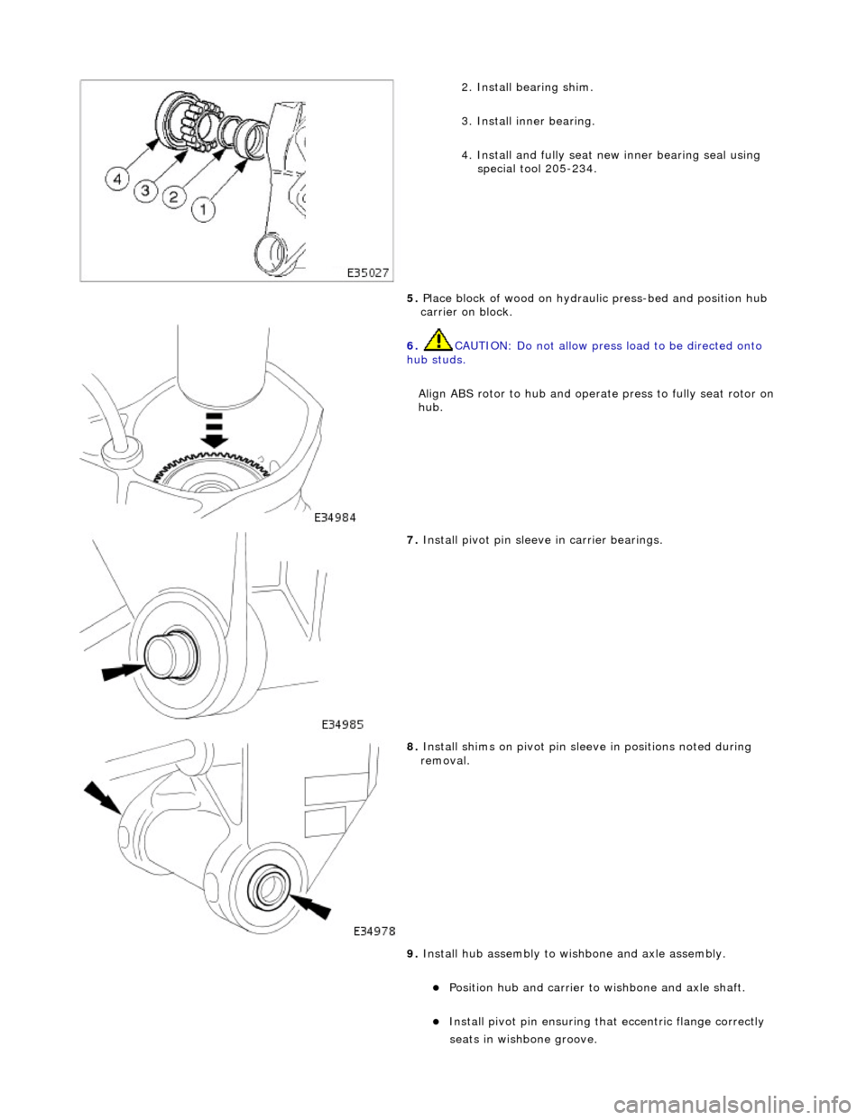
2.
Install bearing shim.
3. Install inner bearing.
4. Install and fully seat new inner bearing seal using special tool 205-234.
5. Place block of wood on hydrau lic press-bed and position hub
carrier on block.
6. CAUTIO
N: Do not allow press
load to be directed onto
hub studs.
Align ABS rotor to hub and operat e press to fully seat rotor on
hub.
7. Install piv o
t pin sleeve in carrier bearings.
8. Inst al
l shims on pivot pin slee
ve in positions noted during
removal.
9. Install hub assembly to wi shbone and axle assembly.
Position hub and carr
ier to wishbone and axle shaft.
Install pivo
t pin ensuring that
eccentric flange correctly
seats i
n wishbone groove.
Page 267 of 2490
The
following explanations will help isolate the source of vibration.
Torque Sensitive
This
means that the condition can be impr
oved or made worse by accelerating, dece lerating, coasting, maintaining a steady
vehicle speed, or applying engine torque.
Ve
hicle Speed Sensitive
This means th
at the vibration al
ways occurs at the same vehicle speed and is not affected by engine torque, engine speed
or gear selection.
Engine Speed Sensit
ive
This means th
at the vibration
occurs at varying vehicle spee ds when a different gear is selected. It can sometimes be
isolated by increasing or decreasing engine speed with the tran smission in neutral or by stall testing with the transmission in
gear. If the condition is engine speed sensitive, the cause is probably not related to tires.
If the road test indicates that there is tire wine, but no shake or vibration, the noise originates with the contact between th e
tire and the road surface.
A thumping noise usually means that the tire is flat or has soft spots making a noise as they slap the roadway. Tire whine
can be distinguished from axle no ise, as tire whine remains the same over a range of speeds.
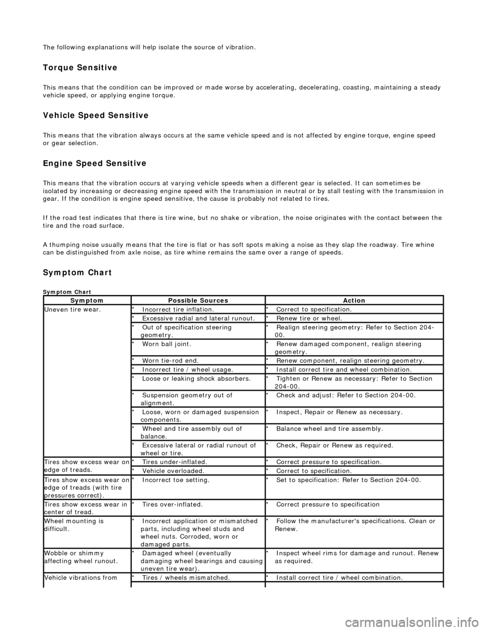
Sym
ptom Chart
Sy
mptom Chart
Sy
mptom
Possib
le Sources
Acti
on
Uneven ti
re wear.
Incorrect ti
re inflation.
*
Cor
rect to specification.
*
Exce
ssive radial an
d lateral runout.
*
Renew tire
or wheel.
*
O
ut of specification steering
geometry.
*
R
ealign steering geometry: Refer to Section 204-
00.
*
W
orn ball joint.
*
Renew
damaged component, realign steering
geometry.
*
W
orn tie-rod end.
*
R
enew component, realign steering geometry.
*
Incorrect
tire / wheel usage.
*
Inst
all correct tire and wheel combination.
*
Loose or leaki
ng shock absorbers.
*
Tigh
ten or Renew as nece
ssary: Refer to Section
204-00.
*
Suspensi
on geometry out of
alignment.
*
Che
ck and adjust: Refer to Section 204-00.
*
Loose, worn or da mage
d suspension
components.
*
In
spect, Repair or Renew as necessary.
*
Wh
eel and tire assembly out of
balance.
*
Balance wheel an
d tire assembly.
*
Excessive later
al or radial runout of
wheel or tire.
*
Check, Repair o
r
Renew as required.
*
Tire
s show excess wear on
edge of treads.
Ti
res under-inflated.
*
Cor
rect pressure to specification.
*
Vehi
cle overloaded.
*
Cor
rect to specification.
*
Tire
s show excess wear on
edge of treads (with tire
pressures correct).
Incorre
ct toe setting.
*
Se
t to specification: Refer to Section 204-00.
*
Tire
s show excess wear in
center of tread.
Tire
s over-inflated.
*
Cor
rect pressure to specification
*
W
heel mounting is
difficult.
Incorrect app
lication or mismatched
parts, including wheel studs and
wheel nuts. Corroded, worn or
damaged parts.
*
Fol
low the manufacturer's specifications. Clean or
Renew.
*
Wobble or sh
immy
affecting wheel runout.
Damaged wh
eel (eventually
damaging wheel bearings and causing
uneven tire wear).
*
Inspect wheel rims for
damage and runout. Renew
as required.
*
Vehicle vibrations from
Tire
s / wheels mismatched.
*
Inst
all correct tire / wheel combination.
*