injection JAGUAR X308 1998 2.G User Guide
[x] Cancel search | Manufacturer: JAGUAR, Model Year: 1998, Model line: X308, Model: JAGUAR X308 1998 2.GPages: 2490, PDF Size: 69.81 MB
Page 744 of 2490
Engine - Intake Manifold Gasket RH
In-vehicle Repair
1. Open the engine compartment and fit paintwork protection
sheets.
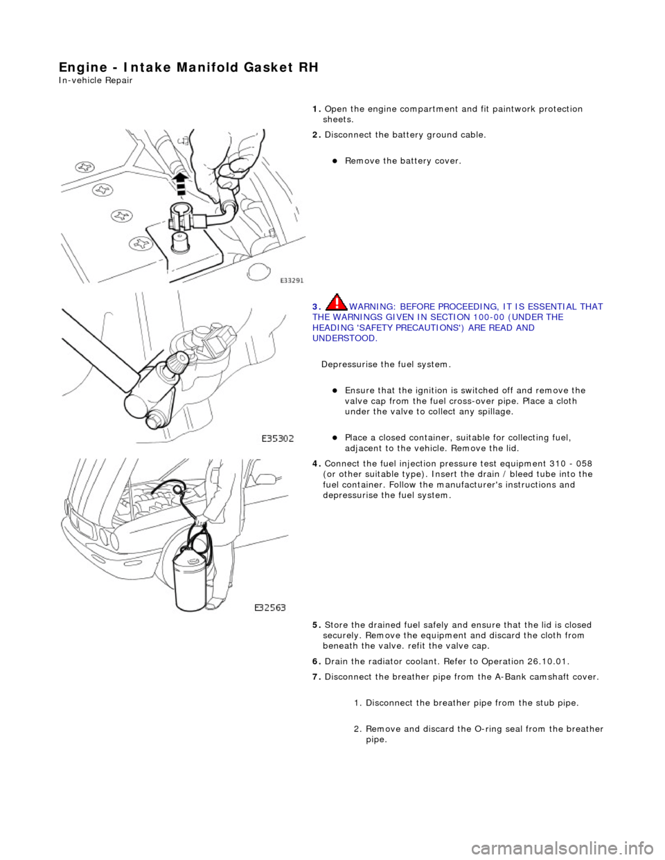
2. Disconnect the batt ery ground cable.
Remove the battery cover.
3. WARNING: BEFORE PROCEEDING, IT IS ESSENTIAL THAT THE WARNINGS GIVEN IN SECTION 100-00 (UNDER THE
HEADING 'SAFETY PRECAUTIONS') ARE READ AND
UNDERSTOOD.
Depressurise the fuel system.
Ensure that the ignition is switched off and remove the
valve cap from the fuel cross-over pipe. Place a cloth
under the valve to collect any spillage.
Place a closed container, su itable for collecting fuel,
adjacent to the vehicle. Remove the lid.
4. Connect the fuel injection pres sure test equipment 310 - 058
(or other suitable type). Insert the drain / bleed tube into the
fuel container. Follow the ma nufacturer's instructions and
depressurise the fuel system.
5. Store the drained fuel safely and ensure that the lid is closed
securely. Remove the equipmen t and discard the cloth from
beneath the valve. refit the valve cap.
6. Drain the radiator coolant. Refer to Operation 26.10.01.
7. Disconnect the breather pipe fro m the A-Bank camshaft cover.
1. Disconnect the breather pipe from the stub pipe.
2. Remove and discard the O-ring seal from the breather
pipe.
Page 896 of 2490
Engine - Engine
Removal
Removal
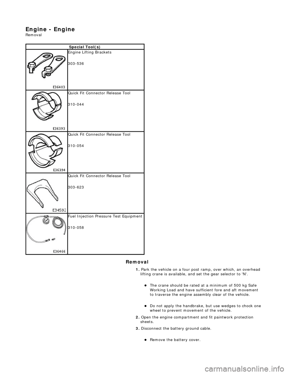
Special Tool(s)
Engine Lifting Brackets
303-536
Quick Fit Connector Release Tool
310-044
Quick Fit Connector Release Tool
310-054
Quick Fit Connector Release Tool
303-623
Fuel Injection Pressure Test Equipment
310-058
1. Park the vehicle on a four post ramp, over which, an overhead
lifting crane is available, and set the gear selector to 'N'.
The crane should be rated at a minimum of 500 kg Safe
Working Load and have suffici ent fore and aft movement
to traverse the engine assemb ly clear of the vehicle.
Do not apply the handbrake, but use wedges to chock one
wheel to prevent movement of the vehicle.
2. Open the engine compartment and fit paintwork protection
sheets.
3. Disconnect the batt ery ground cable.
Remove the battery cover.
Page 898 of 2490
ENSURE THAT ALL FIRE PREVENTION PROCEDURES ARE ACTIVE.
BEFORE PROCEEDING, IT IS ESSENTIAL THAT THE WARNING NOTES GIVEN IN SECTION 100-00 (UNDER THE
HEADING 'SAFETY PRECAUTIONS') ARE READ AND UNDERSTOOD.
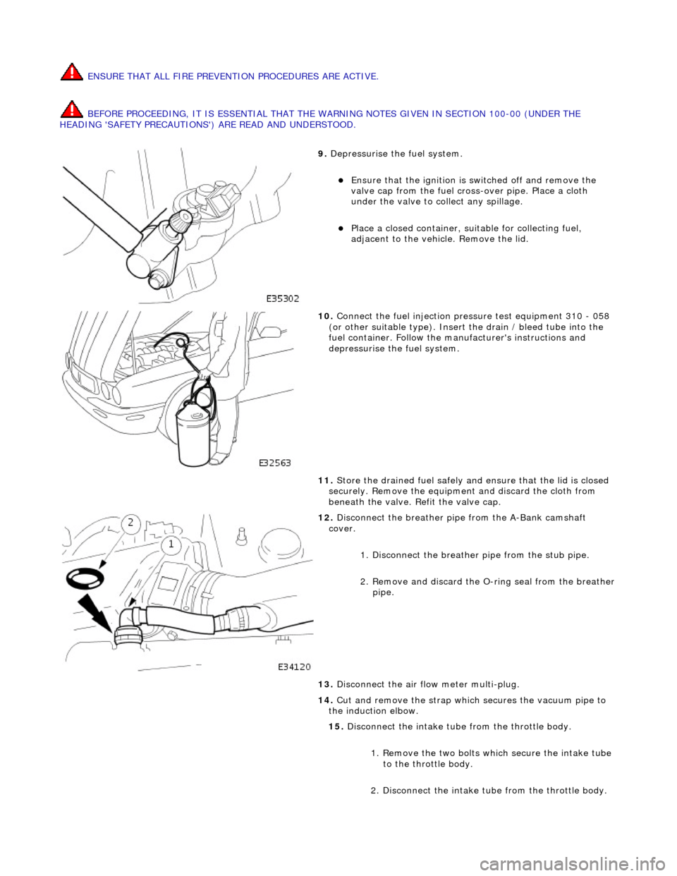
9. Depressurise the fuel system.
Ensure that the ignition is switched off and remove the
valve cap from the fuel cross-over pipe. Place a cloth
under the valve to collect any spillage.
Place a closed container, su itable for collecting fuel,
adjacent to the vehicle. Remove the lid.
10. Connect the fuel injection pressure test equipment 310 - 058
(or other suitable type). Insert the drain / bleed tube into the
fuel container. Follow the ma nufacturer's instructions and
depressurise the fuel system.
11. Store the drained fuel safely and ensure that the lid is closed
securely. Remove the equipmen t and discard the cloth from
beneath the valve. Refit the valve cap.
12. Disconnect the breather pipe from the A-Bank camshaft
cover.
1. Disconnect the breather pipe from the stub pipe.
2. Remove and discard the O-ring seal from the breather
pipe.
13. Disconnect the air flow meter multi-plug.
14. Cut and remove the strap which secures the vacuum pipe to
the induction elbow.
15. Disconnect the intake tube from the throttle body.
1. Remove the two bolts which secure the intake tube to the throttle body.
2. Disconnect the intake tube from the throttle body.
Page 911 of 2490
Engine - Engine
Installation
Installation
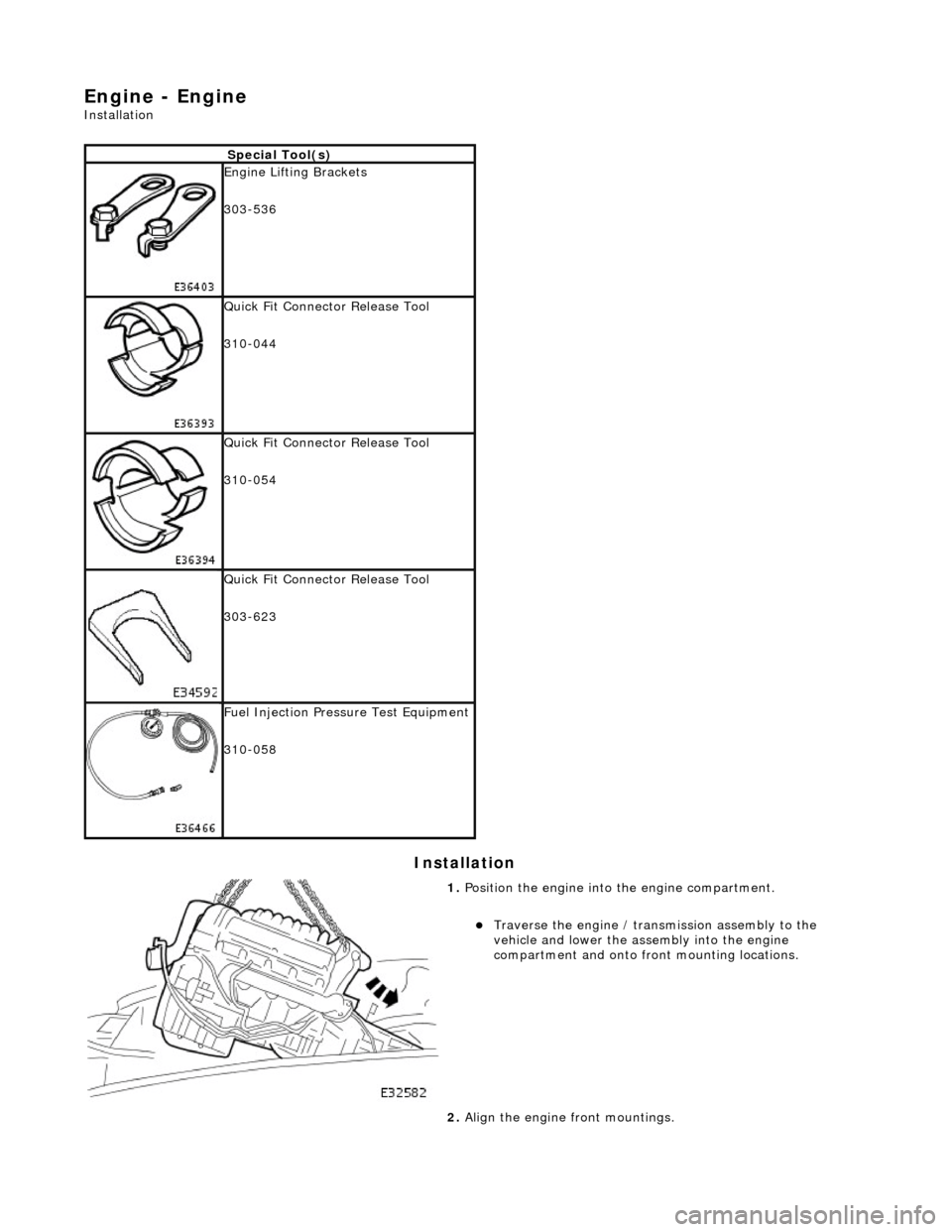
Special Tool(s)
Engine Lifting Brackets
303-536
Quick Fit Connector Release Tool
310-044
Quick Fit Connector Release Tool
310-054
Quick Fit Connector Release Tool
303-623
Fuel Injection Pressure Test Equipment
310-058
1. Position the engine into the engine compartment.
Traverse the engine / transmission assembly to the
vehicle and lower the assembly into the engine
compartment and onto front mounting locations.
2. Align the engine front mountings.
Page 1015 of 2490
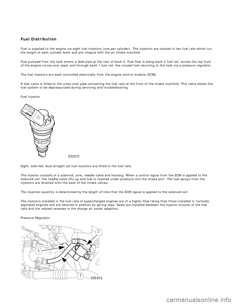
Fuel D
istribution
Fuel is supplied to th
e engine
via eight fuel injectors (one pe r cylinder). The injectors are located in two fuel rails which r un
the length of each cylinder bank and ar e integral with the air intake manifold.
Fuel pumped from the tank enters a feed pipe at the rear of bank 2. Fuel flow is along bank 2 fuel rail, across the top front
of the engine (cross-over pipe) and through bank 1 fuel rail, the unused fuel re turning to the tank via a pressure regulator.
The fuel injectors are each controlled electrically from the engine control module (ECM).
A test valve is fitted to the cross-over pipe connecting the fu el rails at the front of the intake manifold. This valve allows the
fuel system to be depr essurized during servicin g and troubleshooting.
Fuel Injector
Eight, side-fed, dual straight-jet fuel injectors are fi tted in the fuel rails.
The injector consists of a solenoid, core, needle valve and ho using. When a control signal from the ECM is applied to the
solenoid coil, the needle valve lifts up and fuel is injected under pressure into the intake port. The fuel sprays from the
injectors are directed onto the back of the intake valves.
The injection quantity is determined by the length of time that the ECM signal is applied to the solenoid coil.
The injectors installed in the fuel rails of supercharged engines are of a higher flow rating than those installed in normally
aspirated engines and are secured in position by spring clips. Seals are instal led between the injector mounts of the fuel
rails and the related re cesses in the charge air cooler adaptors.
Pressure Regulator
Page 1016 of 2490
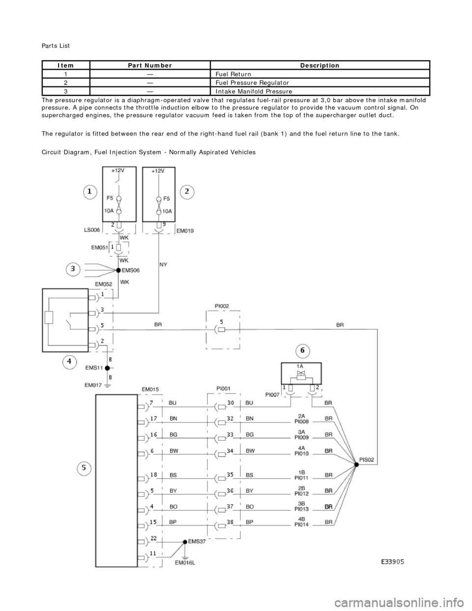
Pa
rts List
The pressure regulator is a diap hragm-operated valve that regula tes fuel-rail pressure at 3,0 bar above the intake manifold
pressure. A pipe connects the throttle induction elbow to the pressure regulator to provide the vacuum control signal. On
supercharged engines, the pressure regulator vacuum feed is taken from the top of the supercharger outlet duct.
The regulator is fitted between the rear end of the right-hand fuel rail (bank 1) and the fuel return line to the tank.
Circuit Diagram, Fuel Injection Syst em - Normally Aspirated Vehicles
Ite
m
Par
t
Number
De
scr
iption
1—F
u
el Return
2—F
u
el Pressure Regulator
3—Inta
k
e Manifold Pressure
Page 1017 of 2490
Ci
rcuit references to injectors:
'A' refers to bank 1;
'B' refers to bank 2.
Fuel C
harging and Controls - Supercharged Vehicles
Ci
rcuit Diagram, Fuel Injection
System - Supercharged Vehicles
It
em
Par
t Number
De
scription
1—E
ngine compartment fuse-box
2—Engine
management fuse-box
3—Splice
- 12V to
other circuits
4—PI m
ain relay
5—Engine
control module (ECM)
6—Fue
l injector 1A - other injectors similar
Page 1029 of 2490
ci
rcuit includes the EMS fuse box,
fuse 05, and the fuel injection relay. For additional information,
refer to the wiring diagrams. CLEAR DTC. TEST the system for normal operation.
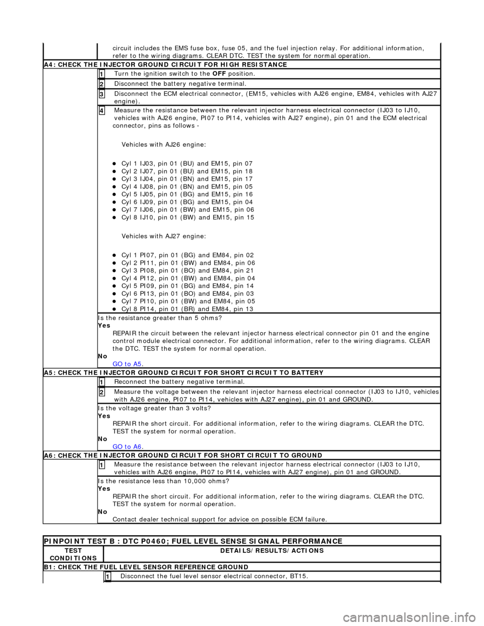
A4: CHECK
THE INJECTOR GROUND
CIRCUIT FOR HIGH RESISTANCE
Turn the ignition swi
tch to the OFF
position.
1
Di
sconnect the battery negative terminal.
2
D
isconnect the ECM electrical connector, (EM15, vehi
cles with AJ26 engine, EM84, vehicles with AJ27
engine).
3
Meas
ure the resistance between the relevant injector harness electrical connector (IJ03 to IJ10,
vehicles with AJ26 engine, PI07 to PI14, vehicles with AJ27 engine), pin 01 and the ECM electrical
connector, pins as follows -
Vehicles with AJ26 engine:
Cy
l 1 IJ03, pin 01 (BU) and EM15, pin 07
Cy
l 2 IJ07, pin 01 (BU) and EM15, pin 18
Cy
l 3 IJ04, pin 01 (BN) and EM15, pin 17
Cy
l 4 IJ08, pin 01 (BN) and EM15, pin 05
Cy
l 5 IJ05, pin 01 (BG) and EM15, pin 16
Cy
l 6 IJ09, pin 01 (BG) and EM15, pin 04
Cy
l 7 IJ06, pin 01 (BW) and EM15, pin 06
Cy
l 8 IJ10, pin 01 (BW) and EM15, pin 15
Vehicles with AJ27 engine:
Cy
l 1 PI07, pin 01 (B
G) and EM84, pin 02
Cy
l 2 PI11, pin 01 (BW) and EM84, pin 06
Cy
l 3 PI08, pin 01 (BO) and EM84, pin 21
Cy
l 4 PI12, pin 01 (BW) and EM84, pin 04
Cy
l 5 PI09, pin 01 (B
G) and EM84, pin 14
Cy
l 6 PI13, pin 01 (BO) and EM84, pin 03
Cy
l 7 PI10, pin 01 (BW) and EM84, pin 05
Cy
l 8 PI14, pin 01 (BR) and EM84, pin 13
4
Is th
e resistance greater than 5 ohms?
Yes REPAIR the circuit between the relevant injector harness electrical connector pin 01 and the engine
control module electrical connecto r. For additional information, refer to the wiring diagrams. CLEAR
the DTC. TEST the system for normal operation.
No GO to A5
.
A5: CHECK
THE INJECTOR GROUND CI
RCUIT FOR SHORT CIRCUIT TO BATTERY
R
econnect the battery negative terminal.
1
Meas
ure the voltage between the relevant injector harness electrical connector (IJ03 to IJ10, vehicles
with AJ26 engine, PI07 to PI14, vehicles with AJ27 engine), pin 01 and GROUND.
2
Is th
e voltage greater than 3 volts?
Yes REPAIR the short circuit. For addi tional information, refer to the wiring diagrams. CLEAR the DTC.
TEST the system for normal operation.
No GO to A6
.
A6: CHECK
THE INJECTOR GROUND CI
RCUIT FOR SHORT CIRCUIT TO GROUND
Meas
ure the resistance between the relevant injector harness electrical connector (IJ03 to IJ10,
vehicles with AJ26 engine, PI07 to PI14, vehicles with AJ27 engine), pin 01 and GROUND.
1
Is
the resistance less than 10,000 ohms?
Yes REPAIR the short circuit. For addi tional information, refer to the wiring diagrams. CLEAR the DTC.
TEST the system for normal operation.
No Contact dealer technical support for advice on possible ECM failure.
P
INPOINT TEST B : DTC P0460; FUEL
LEVEL SENSE SIGNAL PERFORMANCE
TE
ST
CONDITIONS
D
ETAILS/RESULTS/ACTIONS
B1: CHECK
THE FUEL LEVEL SENSOR REFERENCE GROUND
Di
sconnect the fuel level sensor electrical connector, BT15.
1
Page 1032 of 2490
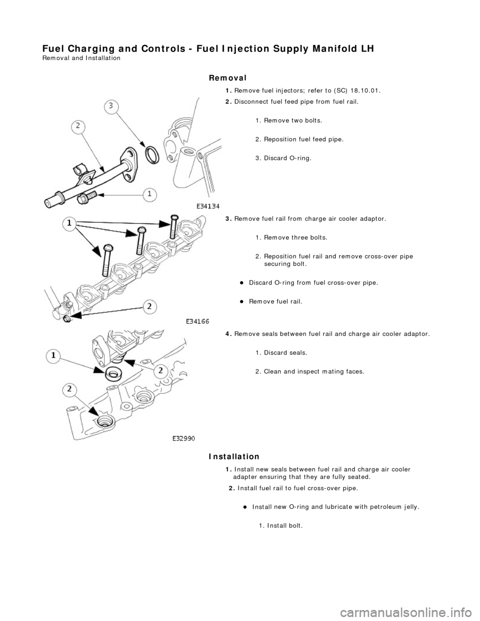
Fuel Char
ging and Controls - Fu
el Injection Supply Manifold LH
Remo
val and Installation
Remov
a
l
Installation
1. Re
move fuel injectors; refer to (SC) 18.10.01.
2. Disc
onnect fuel feed
pipe from fuel rail.
1. Remove two bolts.
2. Reposition fuel feed pipe.
3. Discard O-ring.
3. Re
move fuel rail from charge air cooler adaptor.
1. Remove three bolts.
2. Reposition fuel rail and remove cross-over pipe securing bolt.
Di
scard O-ring from fuel cross-over pipe.
R
e
move fuel rail.
4. Re
move seals between fuel rail
and charge air cooler adaptor.
1. Discard seals.
2. Clean and inspect mating faces.
1. Install new seals between fuel rail and charge air cooler
adapter ensuring that they are fully seated.
2. Install fuel rail to fuel cross-over pipe.
Inst al
l new O-ring and lubricate with petroleum jelly.
1. Install bolt.
Page 1034 of 2490
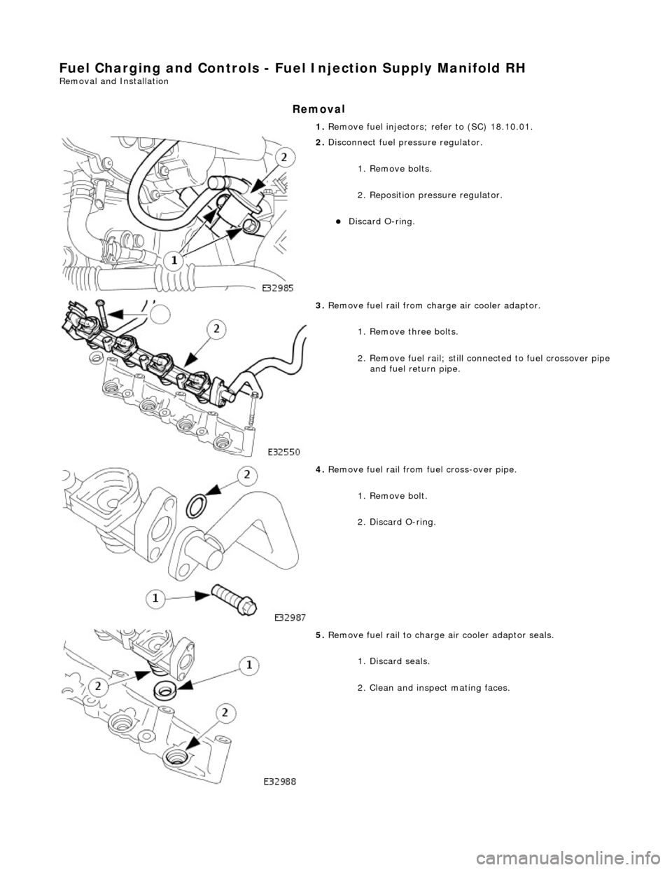
Fuel Char
ging and Controls - Fu
el Injection Supply Manifold RH
Remo
val and Installation
Remov
a
l
1.
Re
move fuel injectors; refer to (SC) 18.10.01.
2. Disc
onnect fuel pressure regulator.
1. Remove bolts.
2. Reposition pres sure regulator.
Disc
ard O-ring.
3. Re
move fuel rail from charge air cooler adaptor.
1. Remove three bolts.
2. Remove fuel rail; still co nnected to fuel crossover pipe
and fuel return pipe.
4. Re
move fuel rail from fuel cross-over pipe.
1. Remove bolt.
2. Discard O-ring.
5. Re
move fuel rail to charge air cooler adaptor seals.
1. Discard seals.
2. Clean and inspect mating faces.