service JAGUAR X308 1998 2.G User Guide
[x] Cancel search | Manufacturer: JAGUAR, Model Year: 1998, Model line: X308, Model: JAGUAR X308 1998 2.GPages: 2490, PDF Size: 69.81 MB
Page 298 of 2490

7. Chec k
that the pinion sp
igot radial run-out.
0,08
mm MAX TIR.
If t
hi
s specification is exceeded, contact Jaguar Service.
8. Re
fer to the illustration.
R
e
new the driveshaft fixings.
9. Re
fer to the illustration.
E
n
sure that the bear
ing is central.
10. Refer to the illustration.
Page 326 of 2490
Fr
ont Brake Disc Runout Check Vehicles With: Brembo Brakes
Special Service tools
Di
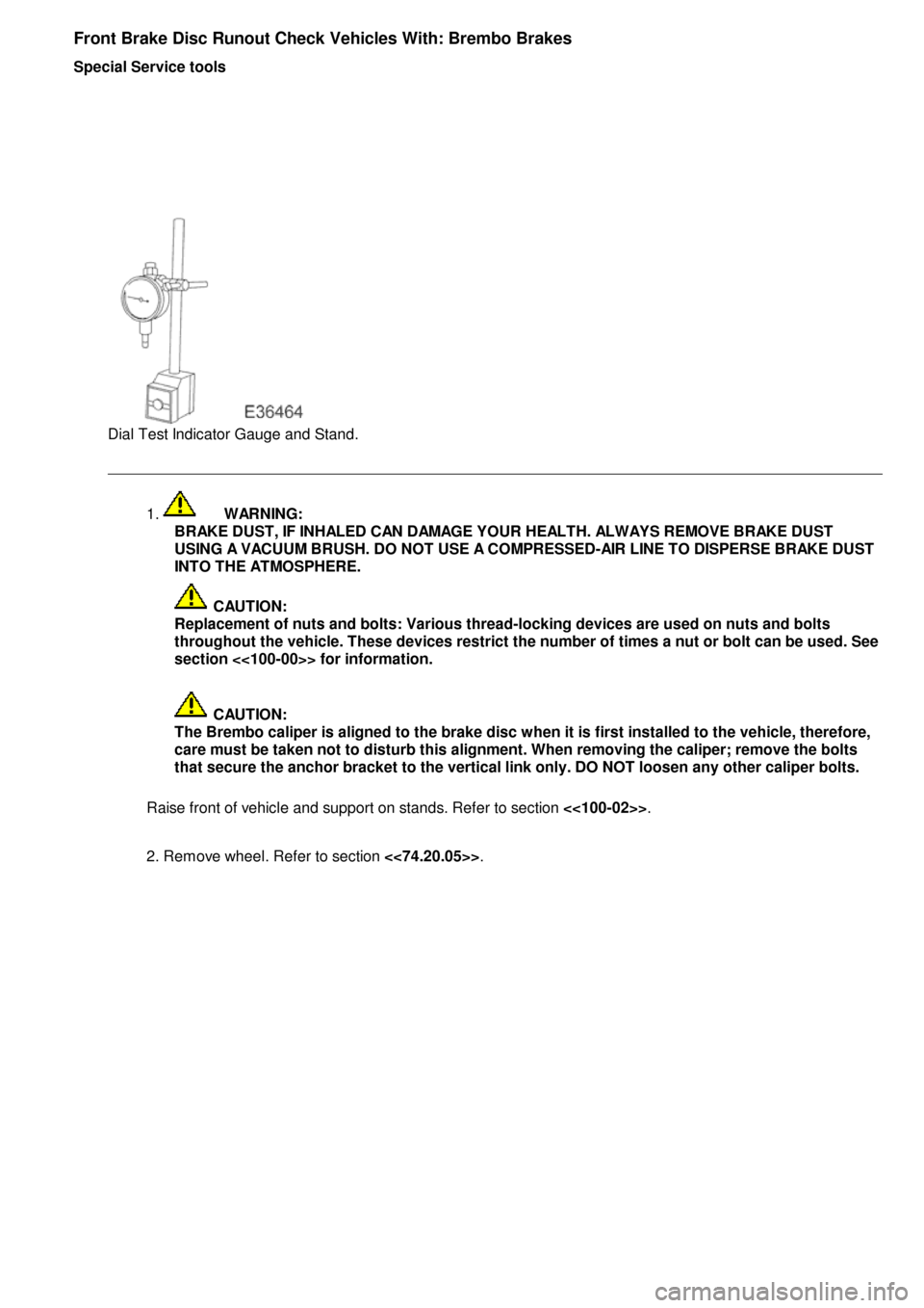
al Test Indicator Gauge and Stand.
1.
WA
RNING:
BRAKE DUST, IF INHALED CAN DAMAGE YOUR HEALTH. ALWAYS REMOVE BRAKE DUST USING A VACUUM BRUSH. DO NOT USE A COMPRESSED-AIR LINE TO DISPERSE BRAKE DUST
INTO THE ATMOSPHERE.
CA
UTION:
Replacement of nuts and bolts: Various thread-locking devices are used on nuts and bolts
throughout the vehicle. These devices restrict the number of times a nut or bolt can be used. See
section <<100-00>> for information.
CA
UTION:
The Brembo caliper is aligned to the brake disc when it is first installed to the vehicle, therefore,
care must be taken not to disturb this alignment. When removing the caliper; remove the bolts
that secure the anchor bracket to the vertical link only. DO NOT loosen any other caliper bolts.
Raise front of vehicle and support on stands. Refer to section <<100-02>>.
2. Remove wheel. Refer to section <<74.20.05>>.
Page 331 of 2490
R
ear Brake Disc Runout Check Vehicles Without: Brembo Brakes
Special Service tools
D
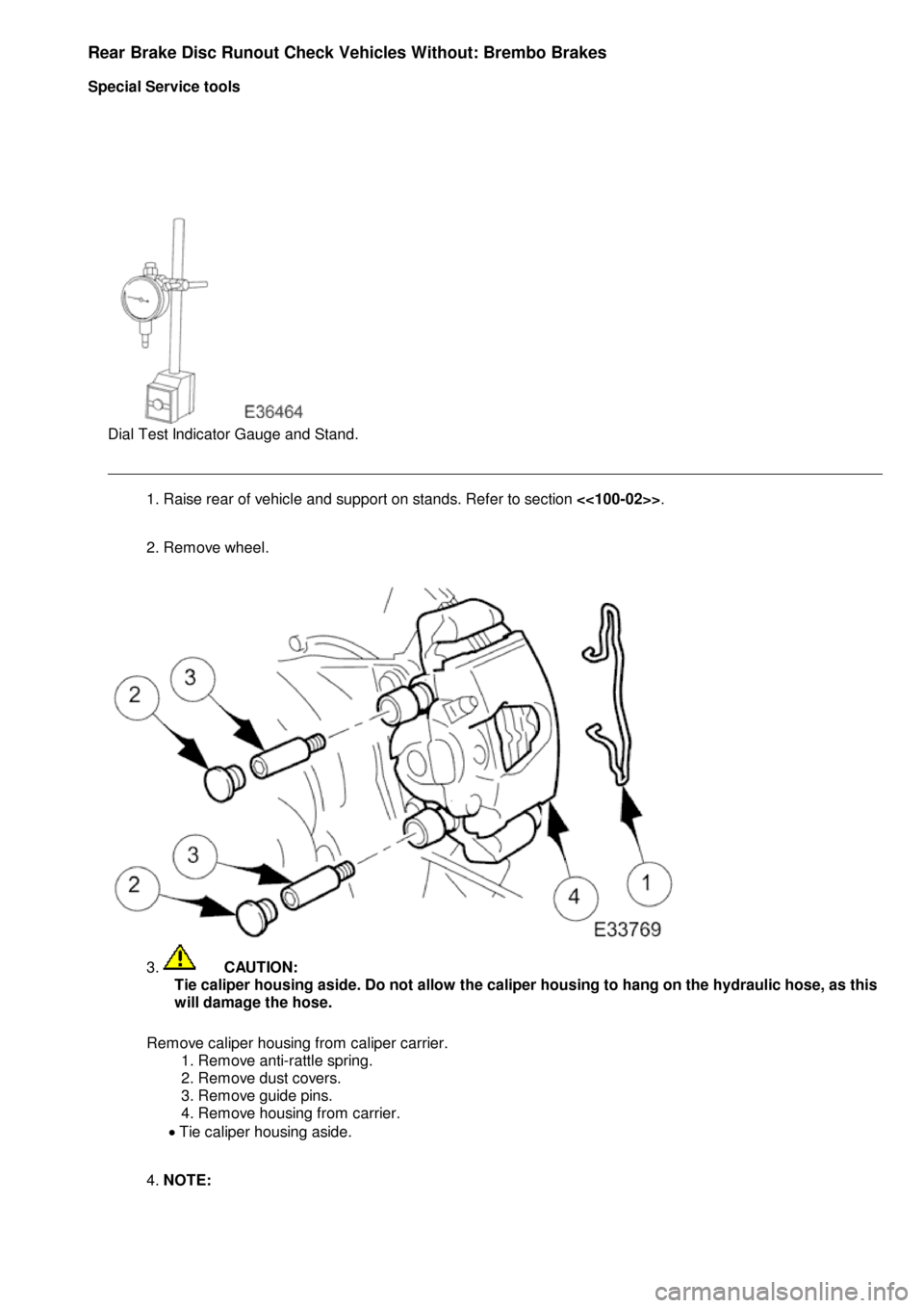
ial Test Indicator Gauge and Stand.
1
. Raise rear of vehicle and support on stands. Refer to section
<<100-02>>.
2. Remove wheel.
3
.
C
AUTION:
Tie caliper housing aside. Do not allow the caliper housing to hang on the hydraulic hose, as this
will damage the hose.
Remove caliper housing from caliper carrier. 1. Remove anti-rattle spring.
2. Remove dust covers.
3. Remove guide pins.
4. Remove housing from carrier.
Tie caliper housing aside.
4. NOTE:
Page 334 of 2490
Rear
Brake Disc Runout Check Vehicles With: Brembo Brakes
Special Service tools
Di
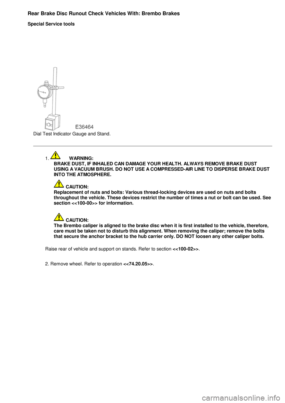
al Test Indicator Gauge and Stand.
1.
WA
RNING:
BRAKE DUST, IF INHALED CAN DAMAGE YOUR HEALTH. ALWAYS REMOVE BRAKE DUST USING A VACUUM BRUSH. DO NOT USE A COMPRESSED-AIR LINE TO DISPERSE BRAKE DUST
INTO THE ATMOSPHERE.
CA
UTION:
Replacement of nuts and bolts: Various thread-locking devices are used on nuts and bolts
throughout the vehicle. These devices restrict the number of times a nut or bolt can be used. See
section <<100-00>> for information.
CA
UTION:
The Brembo caliper is aligned to the brake disc when it is first installed to the vehicle, therefore,
care must be taken not to disturb this alignment. When removing the caliper; remove the bolts
that secure the anchor bracket to the hub carrier only. DO NOT loosen any other caliper bolts.
Raise rear of vehicle and support on stands. Refer to section <<100-02>>.
2. Remove wheel. Refer to operation <<74.20.05>>.
Page 361 of 2490
Front Dis
c Brake - Brake PadsVehicl
es With: High Performance Brakes
Re
moval and Installation
Remov
al
1.
W
ARNING: BRAKE DUST, IF INHALED CAN DAMAGE
YOUR HEALTH. ALWAYS REMOVE BRAKE DUST USING A VACUUM
BRUSH. DO NOT USE A COMPRE SSED-AIR LINE TO DISPERSE
BRAKE DUST INTO THE ATMOSPHERE. Failure to follow this
instruction may result in personal injury.
• CAUTIONS:
Brake pads must always be replaced in axle sets.
Replacement of nuts and bolts: Various thread-locking
devices are used on nuts and bolts throughout the vehicle. These
devices restrict the number of ti mes a nut or bolt can be used.
For additional information, refer to: General Service Information
(10
0-00 General Information,
Description and Operation).
The High Performance brake ca liper is aligned to the brake
disc when it is first installed to the vehicle, therefore, care must
be taken not to disturb this alignment. When removing the
caliper; remove the bolts that se cure the anchor bracket to the
vertical link only. DO NOT loosen any other caliper bolts.
Open engine compartment and fit paint work protection covers
to fenders.
2. R
aise front of vehicle an
d support on stands.
For additional information, refer to: Using the Workshop Jack
(10
0-02 Jacking and Lifting, General Procedures).
3. Remove front wheels. Refer to operation.
For additional information, refer to: Wheel and Tire
(20
4-04
Wheels and Tires, Remo val and Installation).
4. CAUTI
ON: Remove brake flui
d spillage immediately from
paint work, with clean water.
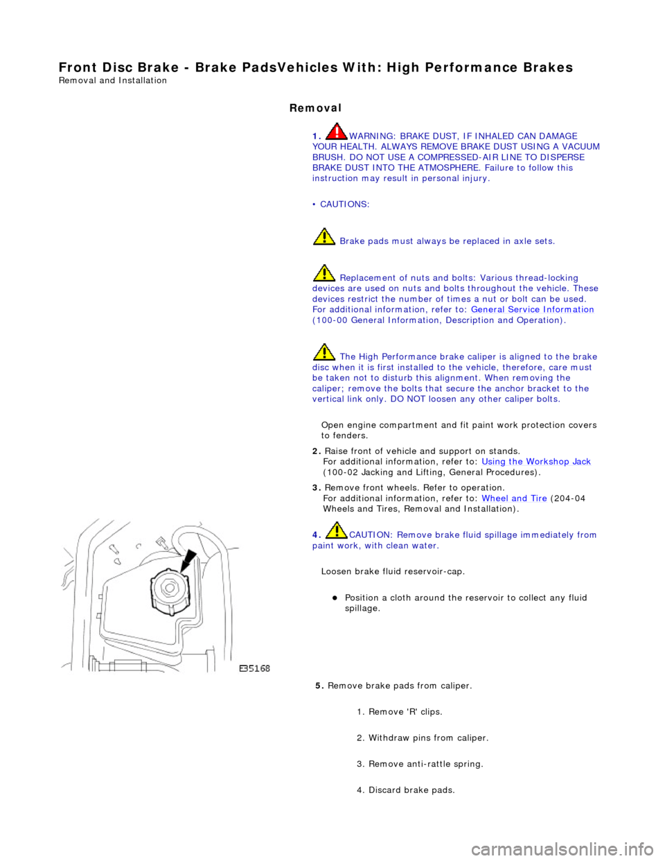
Loosen brake fluid reservoir-cap.
Position a cloth around the
reservoir to collect any fluid
spillage.
5. Remove brake
pads from caliper.
1. Remove 'R' clips.
2. Withdraw pins from caliper.
3. Remove anti-rattle spring.
4. Discard brake pads.
Page 387 of 2490
Rear Dis
c Brake - Brake PadsVehicl
es With: High Performance Brakes
Re
moval and Installation
Remov
al
1.
W
ARNING: BRAKE DUST, IF INHALED CAN DAMAGE
YOUR HEALTH. ALWAYS REMOVE BRAKE DUST USING A VACUUM
BRUSH. DO NOT USE A COMPRE SSED-AIR LINE TO DISPERSE
BRAKE DUST INTO THE ATMOSPHERE. Failure to follow this
instruction may result in personal injury.
• CAUTIONS:
Brake pads must always be replaced in axle sets.
Replacement of nuts and bolts: Various thread-locking
devices are used on nuts and bolts throughout the vehicle. These
devices restrict the number of ti mes a nut or bolt can be used.
For additional information, refer to: General Service Information
(10
0-00 General Information,
Description and Operation).
The High performance brake caliper is aligned to the brake
disc when it is first installed to the vehicle, therefore, care must
be taken not to disturb this alignment. When removing the
caliper; remove the bolts that se cure the anchor bracket to the
vertical link only. DO NOT loosen any other caliper bolts.
Open engine compartment and fit paint work protection covers
to fenders.
2. R
aise rear of vehicle an
d support on stands.
For additional information, refer to: Using the Workshop Jack
(10
0-02 Jacking and Lifting, General Procedures).
3. Remove rear wheels.
For additional information, refer to: Wheel and Tire
(20
4-04
Wheels and Tires, Remo val and Installation).
4. CAUTI
ON: Remove brake flui
d spillage immediately from
paint work, with clean water.
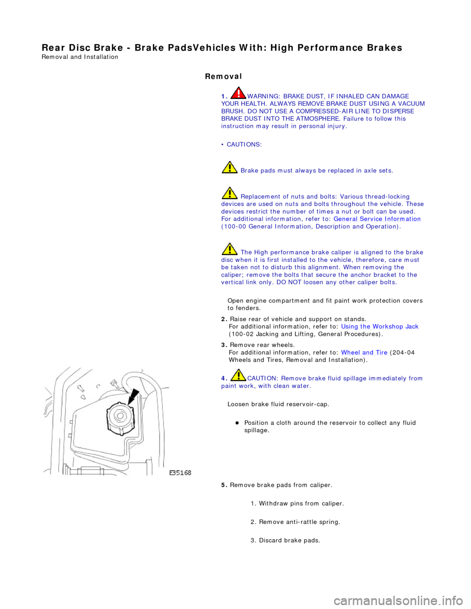
Loosen brake fluid reservoir-cap.
Position a cloth around the
reservoir to collect any fluid
spillage.
5. Remove brake
pads from caliper.
1. Withdraw pins from caliper.
2. Remove anti-rattle spring.
3. Discard brake pads.
Page 458 of 2490
The
measurement of the maximum system pressure, (which is
governed by the pressure relief valve) is achieved by
inserting the Service Tool (pressure gauge and adaptors) into th e fluid circuit of the power steering system. Run the engine
at idle speed, turn the st eering from lock to lock and read the ma ximum pressure recorded on the gauge.
Installin
g Test Equipment
To
in
stall the pressure test equipment:
Pla
c
e a suitable drain tray be
low the power steering pump.
Install a hose clamp on
the re
servoir to pump hose prior to disconnecting any hoses, to avoid unnecessary loss of
fluid.
Disc
onnect the hose from the power st
eering pump high pressure outlet.
Install the pu
mp outlet to hose adaptor (5
). Do not omit the 'O' ring seal (9).
Connect the power steering
pump
adaptor to control valve hose (6) of the test equipment.
Install th e adaptor (4) in th
e high
pressure hose previously removed from the power steering pump outlet.
Conn
ect the connector (3) of the test equipment hose (2) to the adaptor (4).
R
e
move the hose clamp fro
m the reservoir hose.
Start th
e engine.
With the control valve (7) OPEN and the engine idli ng, the following system pressures may be checked:
Du
ring turning.
W
h
en the steering is
held on full lock.
With
the steeri
ng at rest.
• CAUTIONS:
To avoid excessive heating of the po wer steering pump, do not close the valve for longer than 5 seconds maximum.
Do not drive the vehicle with the test equipment installed.
With the control valve (7) CLOSED the power steering pump maximum ou tput pressure can be checked.
Removing Test Equipment
To
remove the test equipment:
Install a hose clamp
on
the reservoir to power steering pump hose.
Re
movi
ng the test equipmen
t is a reversal of the in stallation instructions.
Install a new '
O
' ring seal (9) to the power steering pump high pressu
re outlet to hose connection.
Instal
l the original hose to
the power steering pump.
Re
move the clamp from the reservoir to
the power steering pump hose.
Top-up the reservoir flui
d.
Ble
e
d the power steerin
g system. For additional information,
REFER to Power Steering System Bleeding
- in thi
s section.
Stee
ring Fault Diagnosis by Sympt
om Charts
Leakage
52
11-0
11-03/1
Pump High Pressure Ou
tlet
to Hose Adaptor
621
1
-011-02
Pump Adaptor
to Contro
l Valve Hose
721
1
-011-01
Control Valve
82
11-
011
Pressure Gauge
9-'O
'
Ring Seal
Cond
iti
on
Possib
l
e Sources
Acti
o
n
Co
nfirm
the position of the fluid
leak.
CLEAN th
e area of the leak.
In
s
pect the area and confirm the exact position of leak.
Make sure the fluid
is not from anoth
er system on
the vehicle.
Page 465 of 2490

Description of General Stee
ring System Noises
Boom
Rh
ythmic sound like a drum roll or distant
thunder. May cause pressure on the ear drum.
Buzz
Low-pitched soun
d, like a bee. Usually associated with vibrations.
Chatt
er
Rapidly rep
eating
metallic sound.
Chuckle
Rapid noise that soun
ds like
a stick against the spokes of a spinning bicycle wheel.
F
eedback (knocking noises in the
steering gear) - condition where roughness is felt in the steering
wheel by the driver when the vehicle
is driven over rough surfaces
REF
ER to Section 211
-0
3 Steering Linkage
.
Steeri
ng gear
retaining bolts
loose or damaged.
CAU
TION: DO NOT attempt to adjust the
steering gear yoke. Failure to follow this instruction
will result in the steering gear warranty to become
invalid.
CHECK
and TIGHTEN the steering gear
retaining bolts.
INST
ALL new retaining bolts as necessary.
For additional information,
REFER to Section 211
-0
2 Power Steering
.
L
oose suspension
bushing, bolts or ball joints.
TIGHTE
N or INSTALL new components as
necessary. For additi onal information,
REFER to Section 204
-01
Front Suspension
.
Steeri
ng column
retaining bolts loose.
CAU
TION: DO NOT attempt to adjust the
steering gear yoke. Failure to follow this instruction
will result in the steering gear warranty to become
invalid.
CHECK
and TIGHTEN the steering column
retaining bolts/nuts and pinch bolts if required. For additional information,
REFER to Section 211
-0
4 Steering Column
.
Exce
ssive wear in
steering column assembly.
CHECK
for steering column for wear in the
universal joints and be arings. If wear is
present, INSTALL a new steering column as
necessary. For additi onal information,
REFER to Section 211
-0
4 Steering Column
.
Ni
bble (Shimmy) Oscillation of the
steering wheel (not vertical which is SHAKE). This is driven by road wheel imbalance.
Road wh
eel
imbalance.
CHECK
for road wh
eel imbalance.
CHECK for
rele
vant SERVICE
BULLETINS/SERVICE ACTIONS for the
vehicle on Jaguar Communications Online (JCOL) or in hard copy form.
S
teering wheel
replacement.
CHECK for
rele
vant SERVICE
BULLETINS/SERVICE ACTIONS for the
vehicle on Jaguar Communications Online (JCOL) or in hard copy form.
Rac
k replacement.
CHECK for
rele
vant SERVICE
BULLETINS/SERVICE ACTIONS for the
vehicle on Jaguar Communications Online (JCOL) or in hard copy form.
Page 480 of 2490

The steering rack assembly :
Is mounted on the
rear face of the
front suspension crossbeam by two forg ed mounting brackets with resilient
bushes. The bushes are handed (pinion side and non-pinion side) and are orientated according to the vehicle range
application.
Convert s
the rotary motion of the steering wheel, via the steering gear pinion, to the lateral motion of the rack.
F
e
atures a variable ratio steering
rack with integral hydraulic po wer steering cylinder and piston.
Has a hydrauli
c control valve with Servotronic co
ntrol and positive center feel torsion bar.
The basic steering rack assembly is not serviceable. The following components are serviceable items:
Transfer pipework
.
Servotronic valve. Cent
ralizing cap.
O
u
ter ball joint.
Rac
k
gaiter.
Clips and
fittings.
Steering Rack Components
It e
m
Par
t
Number
De
scr
iption
1—Front
su
spension crossbeam
2—Steeri
ng rack housi
ng
3—Hydraulic
control valve housing
4—Moun
ting bracke
t
5—Gait
er
6—Tie
rod
7—O
u
ter ball joint
Steering R
a
ck Assembly
Page 484 of 2490
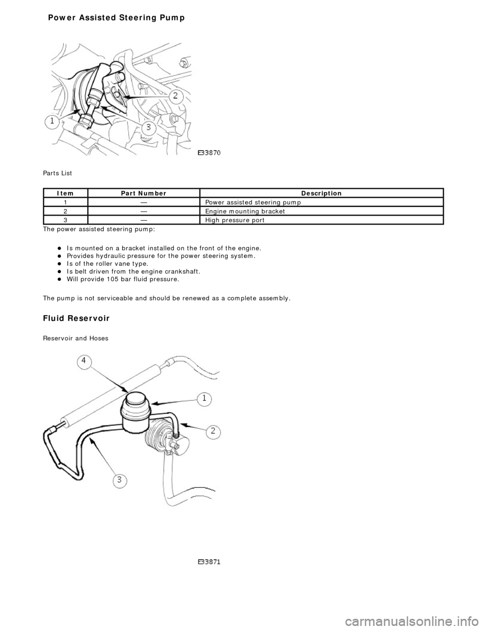
P a
rts List
The power assisted steering pump:
Is mo u
nted on a bracket installe
d on the front of the engine.
Provides hydraul
ic pressure fo
r the power steering system.
Is of the roll
er vane type.
Is belt driven from th
e en
gine crankshaft.
Will provide 1
05 bar f
luid pressure.
The pump is not serviceable and should be renewed as a complete assembly.
Fluid Reservoir
Re
servoir and Hoses
Ite
m
Par
t
Number
De
scr
iption
1—Power as
si
sted steering pump
2—Engine
m
ounting bracket
3—High
pressure port
Power Assisted Steering Pump