service JAGUAR X308 1998 2.G Owner's Guide
[x] Cancel search | Manufacturer: JAGUAR, Model Year: 1998, Model line: X308, Model: JAGUAR X308 1998 2.GPages: 2490, PDF Size: 69.81 MB
Page 550 of 2490
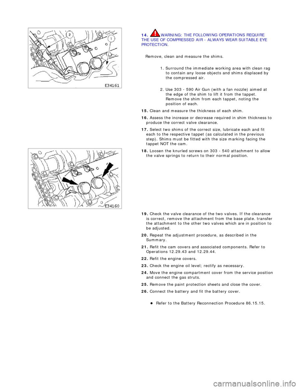
14
. WARNING: TH
E FOLLOWING OPERATIONS REQUIRE
THE USE OF COMPRESSED AIR - ALWAYS WEAR SUITABLE EYE
PROTECTION.
Remove, clean and measure the shims.
1. Surround the immediate wo rking area with clean rag
to contain any loose objects and shims displaced by
the compressed air.
2. Use 303 - 590 Air Gun (with a fan nozzle) aimed at the edge of the shim to lift it from the tappet.
Remove the shim from each tappet, noting the
position of each.
15 . Cl
ean and measure the thickness of each shim.
16. Assess the increase or decrease required in shim thickness to
produce the correct valve clearance.
17. Select two shims of the correct size, lubricate each and fit
each to the respective tappet (as calculated in the previous
step). Shims must be fitted with the size marking facing the
tappet NOT the cam.
18 . Loos
en the knurled screws on 303 - 540 attachment to allow
the valve springs to return to their normal position.
19. Check the valve clearance of the two valves. If the clearance
is correct, remove the attachment from the base plate. transfer
the attachment to the other two valves which are in position to
be adjusted.
20. Repeat the adjustment procedure, as described in the
Summary.
21. Refit the cam covers and associated components. Refer to
Operations 12.29.43 and 12.29.44.
22. Refit the engine covers.
23. Check the engine oil level; rectify as necessary.
24. Move the engine compartment cover from the service position
and connect the gas struts.
25. Remove the paint protection sheets and close the cover.
26. Connect the battery and fit the battery cover.
Refe
r to the Battery Reconnection Procedure 86.15.15.
Page 551 of 2490
E
ngine - Valve Clearance Check
Gen
eral Procedures
1.
Open the engine compartment and fit paintwork protection
sheets. Open to the service position.
2. Carefully remove both engine covers, taking care not to
damage the plasti c fixings or the rubber inserts.
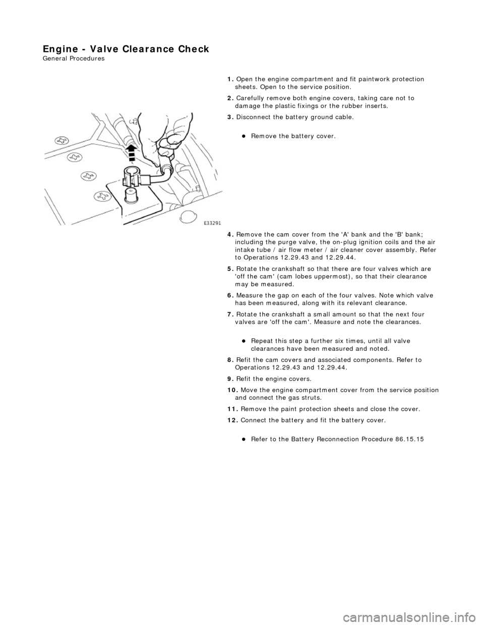
3. Di
sconnect the batt
ery ground cable.
R
emove the battery cover.
4. Remove the cam cover from the 'A' bank and the 'B' bank;
including the purge valve, the on-plug ignition coils and the air
intake tube / air flow meter / air cleaner cover assembly. Refer
to Operations 12.29.43 and 12.29.44.
5. Rotate the crankshaft so that there are four valves which are
'off the cam' (cam lobes upperm ost), so that their clearance
may be measured.
6. Measure the gap on each of the four valves. Note which valve
has been measured, along with its relevant clearance.
7. Rotate the crankshaft a small am ount so that the next four
valves are 'off the cam'. Measure and note the clearances.
Re
peat this step
a further six times, until all valve
clearances have been measured and noted.
8. Refit the cam covers and associated components. Refer to
Operations 12.29.43 and 12.29.44.
9. Refit the engine covers.
10. Move the engine compartment cover from the service position
and connect the gas struts.
11. Remove the paint protection sheets and close the cover.
12. Connect the battery and fit the battery cover.
Re
fer to the Battery Reconnection Procedure 86.15.15
Page 557 of 2490

Engine - Cr
ankshaft Fron
t Seal4.0L NA V8 - AJ 27/3.2L NA V8 - AJ26
In-v
ehicle Repair
Remov
al
S
pecial Tool(s)
Cr
ankshaft locking, main tool
303-191
Adaptor
303-191-02
Crankshaft front
seal remover
303-541
Crankshaft front seal replacer
3
03-542
Crankshaft pull
ey/damper remover
303-588
1. Open the engine compartment and fit paintwork protection
sheets.
2. Set the engine compartment cover to the service access
position.
3. Remove the drive belt from the fro nt accessory drive. Refer to
Operation 12.10.40.
4. Remove the twin fan and motor assembly for access. Refer to
Operation 26.25.12
5. CAUTION: Under no circumstan ces should the crankshaft
setting peg 303-531 be used in the following operations, to lock
the crankshaft.
• NOTE: Should extra locking of the crankshaft be required, use a
lever against one torque converte r boss. Remove the plastic mesh
cover from the torque converter housing for access.
Page 561 of 2490
Engine - Cr
ankshaft Fron
t Seal4.0L SC V8 - AJ26
In-v
ehicle Repair
Remov
al
S
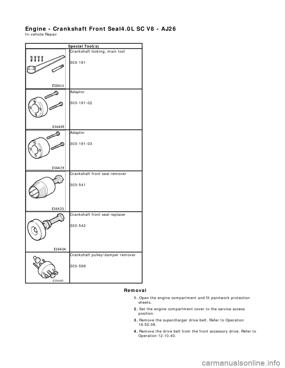
pecial Tool(s)
Cr
ankshaft locking, main tool
303-191
Adaptor
303-191-02
Adaptor
303-191-03
Crankshaft front
seal remover
303-541
Crankshaft front seal replacer
3
03-542
Crankshaft pull
ey/damper remover
303-588
1. Open the engine compartment and fit paintwork protection
sheets.
2. Set the engine compartment cover to the service access
position.
3. Remove the supercharger driv e belt. Refer to Operation
18.50.08.
4. Remove the drive belt from the fro nt accessory drive. Refer to
Operation 12.10.40.
Page 565 of 2490

Engine - Crankshaft
Inner Sp
rocket4.0L NA V8 - AJ27
In-v
ehicle Repair
Remov
al
S
pecial Tool(s)
Camshaft setting
3
03 - 530
T
iming chain tensioning
303 - 532
Wedges, primary ch
ain
303 - 533
Cranksh
aft setting
303 - 531
1. Open the engine compartment and fit paintwork protection
sheets.
2. Set the engine compartment cover to the service access
position.
3. Di
sconnect the batt
ery ground cable.
R
emove the battery cover.
4. Remove the Timing Co ver. Refer to Operation 12.65.01 in this
Section.
5. Remove the VVT bush carrier from the A-Bank.
1. Remove the three bolts which secure the carrier to the cylinder block.
Page 575 of 2490

2
. Fit a new O-ring to the carrier oil-way.
21
.
NOTE: Lubricate the seal (s carf jointed) and the bush.
Fit the VVT bush carrier to the cylinder block.
1. Fit the bush carrier assembly.
1. C
heck that the seals are in place and that the ring
dowels are engaged squa rely. Fully locate the
assembly as much as possible by hand pressure.
2
. Fit the three securing bolts. Tighten to 19 - 23 Nm.
22
.
Fit new seals to the VVT bush carrier, B-Bank.
1. Fit the new sealing ring (scarf jointed) to the carrier bush groove.
2. Fit a new O-ring to the carrier oil-way.
23
.
NOTE: Lubricate the seal (s carf jointed) and the bush.
Fit the VVT bush carrier to the cylinder block. 1. Fit the bush carrier assembly.
1. C
heck that the seals are in place and that the ring
dowels are engaged squa rely. Fully locate the
assembly as much as possible by hand pressure.
2
. Fit the two securing bolts and one nut. Tighten to 19
- 23 Nm.
24. Refit the Timing Cover. Refer to Operation 12.65.01 in this
Section.
25. Move the engine compartment cover from the service position
and connect the gas struts.
26. Remove the paint protection sheets and close the cover.
27. Connect the battery and fit the battery cover.
Re
fer to the Battery Reconnection Procedure 86.15.15.
Page 576 of 2490
Engine - Crankshaft Inner Sprocket3.2L NA V8 - AJ26
In-vehic
le Repair
Remov
a
l
S
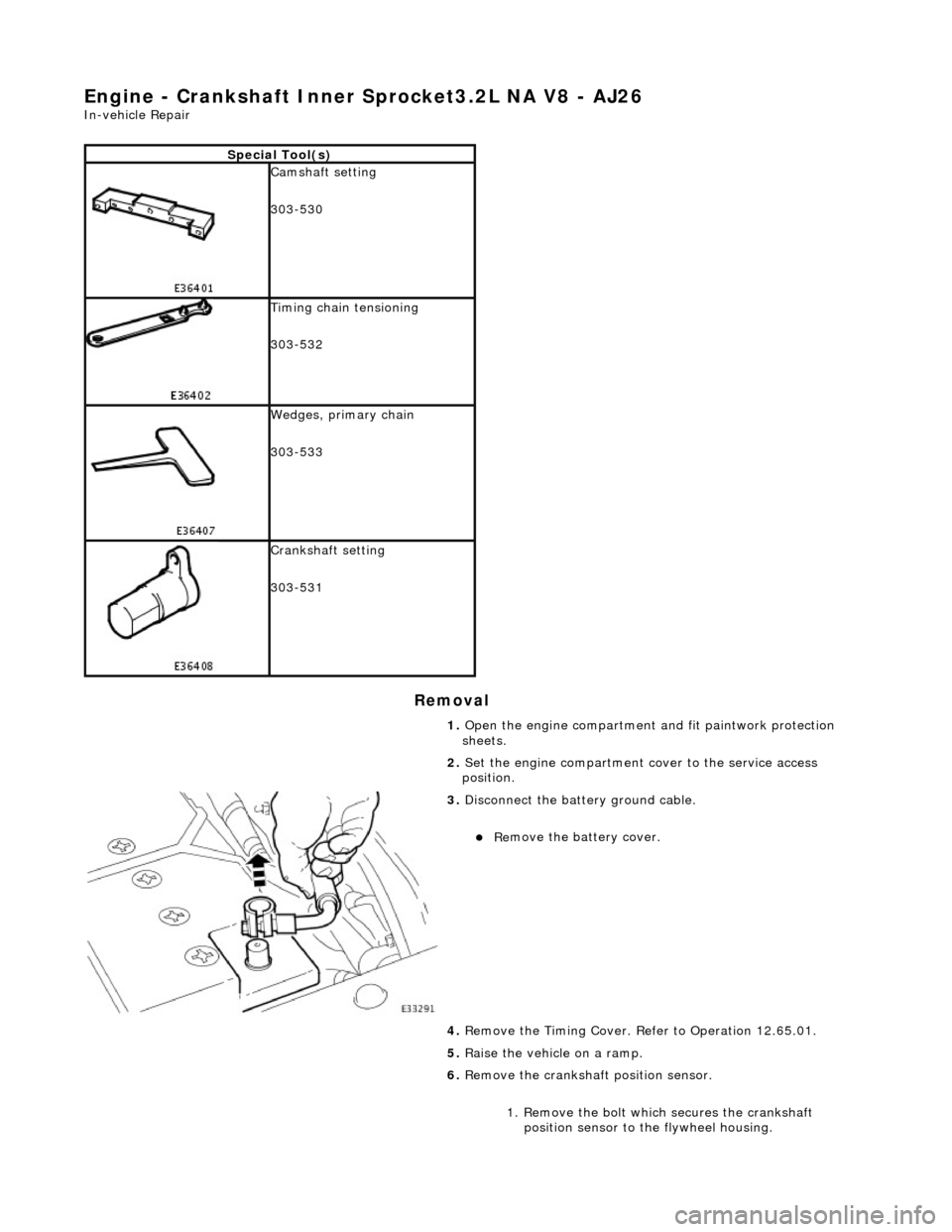
p
ecial Tool(s)
Camshaft setting
3
03-
530
T
i
ming chain tensioning
303-532
Wedges, primary ch ain
303-533
Cranksha
ft setting
303-531
1. Open the engine compartment and fit paintwork protection
sheets.
2. Set the engine compartment cover to the service access
position.
3. Disc
onnect the batt
ery ground cable.
Re
move the battery cover.
4. Remove the Timing Cover. Re fer to Operation 12.65.01.
5. Raise the vehicle on a ramp.
6. Remove the crankshaft position sensor.
1. Remove the bolt which secures the crankshaft position sensor to the flywheel housing.
Page 584 of 2490
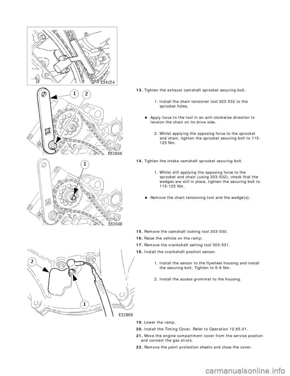
13. Tigh
ten the exhaust camshaft
sprocket securing bolt.
1. Install the chain tensioner tool 303-532 to the sprocket holes.
Appl y force
to the tool in an
anti-clockwise direction to
tension the chain on its drive side.
2. Whilst applying the opposing force to the sprocket and chain, tighten the sprock et securing bolt to 115-
125 Nm.
14 .
Tigh
ten the intake camshaft
sprocket securing bolt.
1. Whilst still applying the opposing force to the
sprocket and chain (using 303-532), check that the
wedges are still in place, ti ghten the securing bolt to
115-125 Nm.
R e
move the chain tensioning
tool and the wedge(s).
15. Remove the camshaft locking tool 303-530.
16. Raise the vehicle on the ramp.
17. Remove the crankshaft setting tool 303-531.
18 . Inst
all the crankshaft position sensor.
1. Install the sensor to the flywheel housing and install
the securing bolt. Tighten to 6-8 Nm.
2. Install the access grommet to the housing.
19. Lower the ramp.
20. Install the Timing Cover. Refer to Operation 12.65.01.
21. Move the engine compartment cover from the service position
and connect the gas struts.
22. Remove the paint protection sheets and close the cover.
Page 586 of 2490

Engine - Crankshaft Outer
Sprocket
In-v
ehic
le Repair
Remov
a
l
S
p
ecial Tool(s)
Camshaft setting
3
03-
530
T
i
ming chain tensioning
303-532
Wedges, primary ch ain
303-533
Cranksha
ft setting
303-531
1. Open the engine compartment and fit paintwork protection
sheets.
2. Set the engine compartment cover to the service access
position.
3. Disc
onnect the batt
ery ground cable.
Re
move the battery cover.
4. Remove the Timing Co ver. Refer to Operation 12.65.01 in this
Section.
5. Remove the VVT bush carrier.
1. Remove the three bolts which secure the carrier to the cylinder block.
Page 592 of 2490

2.
Fit a new O-ring to the carrier oil-way.
14. F
it the VVT bush carrier to the cylinder block.
Lubric
ate the seal (scarf
jointed) and the bush.
1. Fit the bush carrier assembly.
Check that th e seals are in pl ace an
d that the ring dowels
are engaged squarely. Fully locate the assembly as much
as possible by hand pressure.
2. Fit the three securing bolts. Tighten to 19-23 Nm.
15. Refit the Timing Cover. Refer to Operation 12.65.01 in this
Section.
16. Move the engine compartment cover from the service position
and connect the gas struts.
17. Remove the paint protection sheets and close the cover.
18. Connect the battery and fit the battery cover.
Refe
r to the Battery Reconnection Procedure in Section
414-01.