speed control JAGUAR X308 1998 2.G User Guide
[x] Cancel search | Manufacturer: JAGUAR, Model Year: 1998, Model line: X308, Model: JAGUAR X308 1998 2.GPages: 2490, PDF Size: 69.81 MB
Page 265 of 2490
W
heels and Tires - Wheels and Tires
D
iagnosis and Testing
General Not
es
1.
1. Factory in
stalled tires and wheels are designed to provide optimum ride and ha
ndling characteristics when inflated
to the recommended inflation pressures, with vehicle loads not exceeding the full-rated load capacity.
2. 2. Correct tire pressures and driv ing technique have an important influence on tire life. Heavy cornering, excessively
rapid acceleration and unnecessary sharp braking increase tire wear.
3. 3. Replacement tires should follow the recommended:
Size
.
Speed
rating.
Load range. Radial c
onstruction type.
4. 4. The use of any other size or type of wheel / tire may seriously affect:
Safety. Ri
de.
Handlin
g.
Speed
ometer / odometer calibration.
Vehi
cle ground clearance.
Ti
re clearance between
body and chassis.
Wh
eel bearing life.
Brake cooli
ng.
5. 5. Wheels must be renewed when:
Impact damaged. Heavil
y corroded.
Porous W
heel stud holes or se
ats become damaged.
They h
ave excessive radial or lateral runout.
Safety Notes
• WAR
NINGS:
DO NOT MIX DIFFERENT TYPES OF TIRES ON THE SAM E VEHICLE, HANDLING MAY BE SERIOUSLY AFFECTED
RESULTING IN LOSS OF CONTROL.
DO NOT MIX DIFFERENT TYPES OF TIRES ON THE SAM E VEHICLE, HANDLING MAY BE SERIOUSLY AFFECTED
RESULTING IN LOSS OF CONTROL.
A TIRE AND WHEEL MUST ALWAYS BE CORRECTLY MATCHED. WIDER OR NARROWER TIRES THAN RECOMMENDED
COULD CAUSE DANGER THROUGH SUDDEN DEFLATION.
WHEN USING THE TEMPORARY SPARE WHEEL, SPEED MUST NOT EXCEED 80 KM/H (50 MPH). DRIVE WITH CAUTION
AND REPLACE WITH THE SPECIFIED WHEEL / TIRE ASSEMBLY AS SOON AS POSSIBLE.
TRACTION CONTROL (IF AVAILABLE) MUST NOT BE ENGAGED WITH THE TEMPORARY SPARE WHEEL FITTED.
Page 275 of 2490
R
equire no adjustment and are non-serviceable items.
Accelerometers
The three accelerometers:
Sense veh
icle body movement.
Gen
erate an analogue voltag
e (maximum +5 volts) proportional to body movement.
Pr
ovide inputs to the adapti
ve damping control module.
The two vertical acce lerometers are mounted on the bulkhead and in the trunk.
The lateral accelerometer is mounted in the ECM housing.
Ada
ptive Damping Control Module (ADCM)
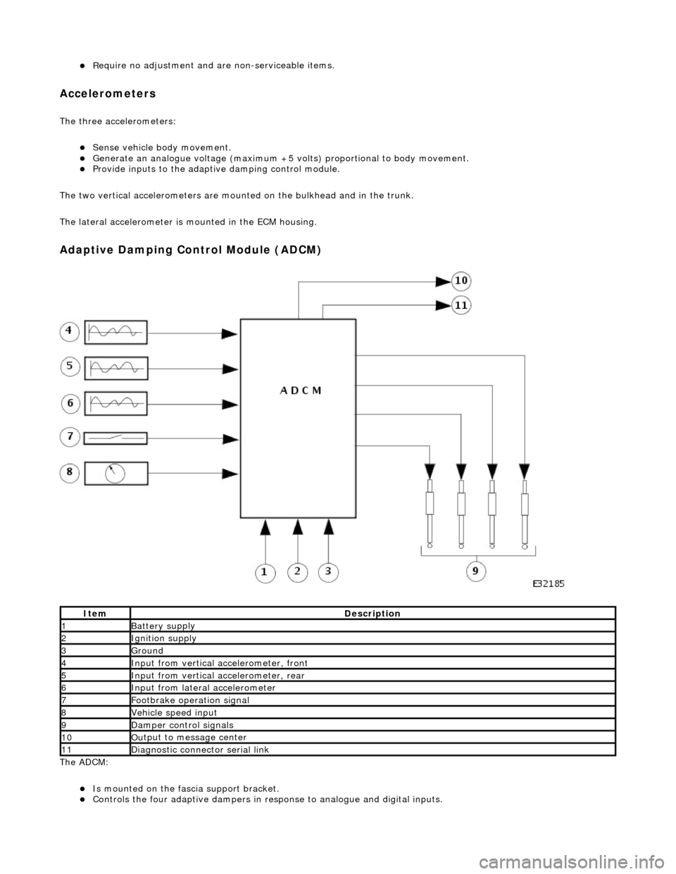
The ADCM
:
Is
mounted on the fascia support bracket.
Controls the four adaptiv
e dampers in re
sponse to analogue and digital inputs.
It
em
De
scription
1Battery su
pply
2Ignition su
pply
3Ground
4Input from verti
cal accelerometer, front
5Input from verti
cal accelerometer, rear
6Input from later
al accelerometer
7F
ootbrake operation signal
8Vehi
cle speed input
9D
amper control signals
10Ou
tput to message center
11D
iagnostic connector serial link
Page 276 of 2490
Is hard-wi
red to the instrume
nt cluster message center.
Is hard
-wired to the J1962 diagnostic connector.
Op
era
tion
Th
e
system selects the soft or
firm damper setting according to the current ro ad and driving conditions, to optimise vehicle
ride and handling.
With the vehicle stationary, the dampers are in the firm setting, but will normally switch to the soft setting when the vehicle
exceeds 8 km/h (5 mile/h); all dampers are switched simultaneously.
Sudden movement of the vehicle body, in response to road inputs, is detected by the vertical accelerometers, and the ADCM
switches the dampers to the firm setting to give improved damping of the resultant oscillations.
When cornering forces are detected by th e lateral accelerometer, the ADCM switches the dampers to the firm setting to
reduce the roll rate an d improve wheel control.
After the event has passed, the dampers revert to the soft setting.
When the footbrake is applied, the ADCM re ceives a signal and calculates the rate of vehicle deceleration. If the deceleration
rate is greater than a certain threshold, the dampers are switched to the firm setting to reduce the pitch rate and improve
wheel control.
If a system failure occurs, the ADCM grounds the output line to the instrument cluster message center, which displays a
text warning SUSPENSION FAULT and illuminates the amber warning lamp. Under fault conditions the system always fails to
the firm setting, so that the vehicle will be safe to drive un der all road and driving conditions.
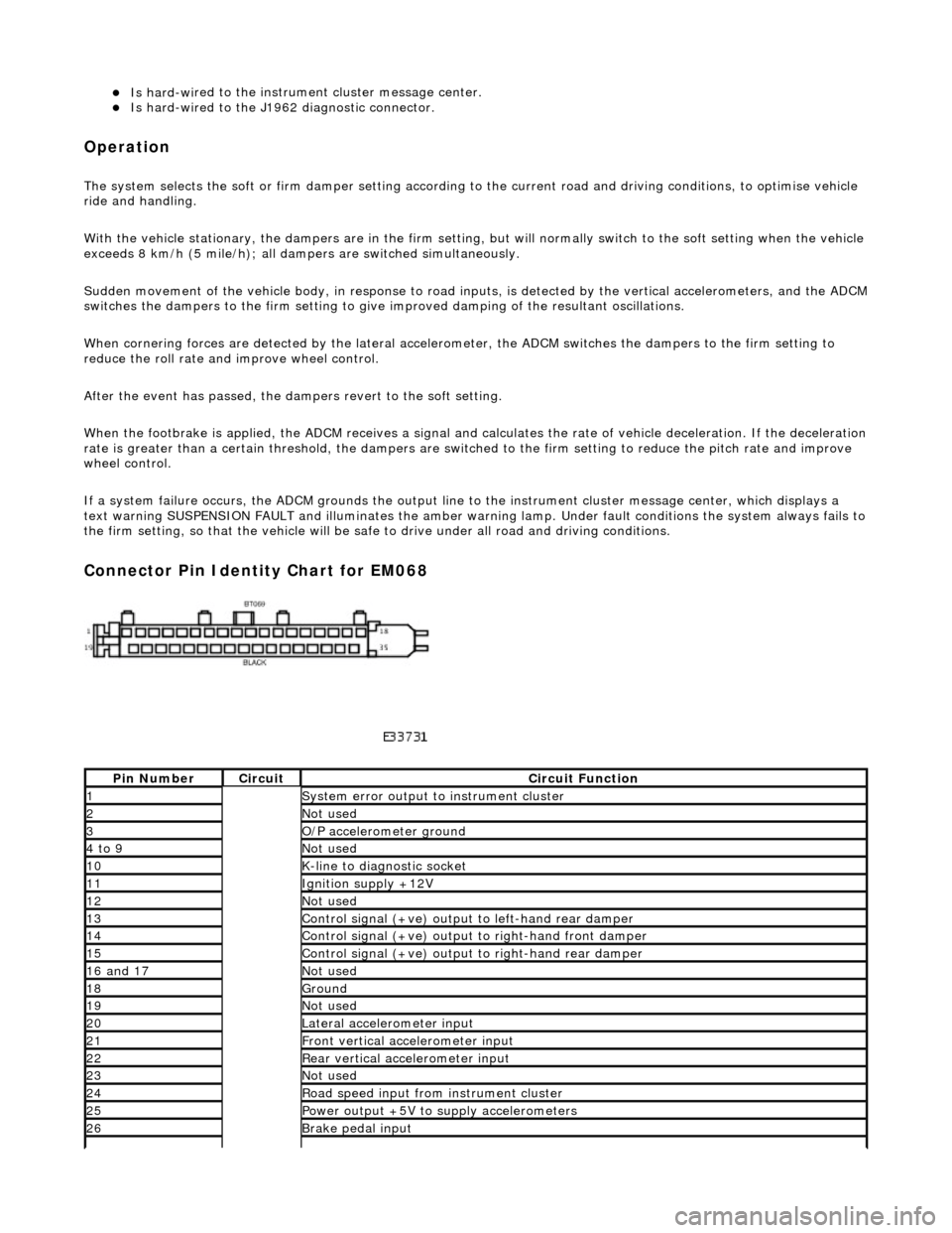
Connector Pin Identity Chart for EM068
Pin
Number
Ci
rcui
t
Circuit Functi
on
1System erro
r output to instrument
cluster
2Not
used
3O/
P a
ccelerometer ground
4 to
9
Not
used
10K-
li
ne to diagnostic socket
11Ignition su
pply +12V
12Not
used
13Control signal (+ve) output
to l
eft-hand rear damper
14Control signal (+ve) output
to right-hand front damp
er
15Control signal (+ve) output
to right-hand rear
damper
16
a
nd 17
No
t
used
18Ground
19No
t
used
20Lateral
accelerometer i
nput
21Front vertical ac
celerometer in
put
22Rear vertical
acce
lerometer input
23No
t
used
24R
o
ad speed input from
instrument cluster
25Power output +5V to suppl y accelerometers
26Brake peda
l input
Page 309 of 2490
Brake System - General Inform
ation - Brake System
D
iagnosis and Testing
Principles of Operations
The brake system operates by transferring effort applied to th e brake pedal, by the driver to the brakes at each wheel.
The braking effort is distributed to each wheel, using a hydraulic system. The system is assisted using a vacuum brake
booster that reduces pedal effort for a given hydraulic pressure. The parking brake operates on the rear wheels and is
applied using a hand operated control.
I
nspection and Verification
•
NOTE: Prior to carrying out any diagno
sis, make sure that the brake system warning indicator is functional.
Visually examine the front and rear tire and wheel assemblies for damage such as un even wear patterns, tread worn out or
sidewall damage. Verify the tires are th e same size, type and, where possible, same manufacture. Replace the damaged
wheel or excessively worn tire. For a dditional information, refer toSection 204
-0
4 Wheels and Tires
.
W
heels and tires must be cleared of an
y foreign matter and tire pressures ad justed to the correct specification.
If the tires exhibit uneven wear or feathering, the cause must be corrected. Check the steering and suspension components
for damage or wear and, if ne cessary, check and adjust front wheel alignment. For additional information, refer toSection
204
-00 Suspen
sion System
- General Informati
on
.
Road Test
V
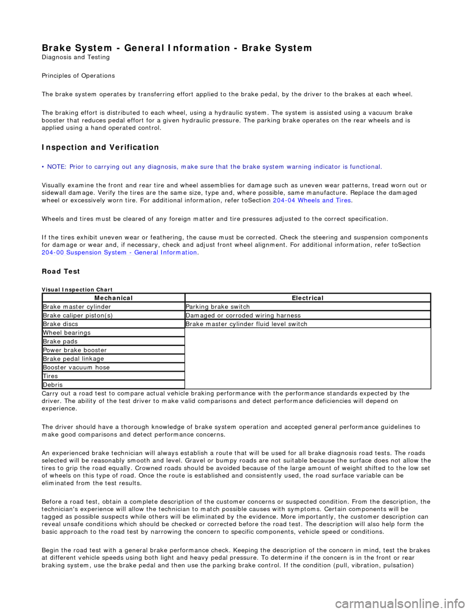
isual Inspection Chart
Carr
y out a road test to compare actual vehicle braking performance with the
performance standards expected by the
driver. The ability of the test driver to make valid compar isons and detect performance deficiencies will depend on
experience.
The driver should have a thorough knowledge of brake system operation and accepted general performance guidelines to
make good comparisons and de tect performance concerns.
An experienced brake technician will always establish a route that will be used for all br ake diagnosis road tests. The roads
selected will be reasonably smooth and level. Gravel or bump y roads are not suitable because the surface does not allow the
tires to grip the road equally. Crowned roads should be avoide d because of the large amount of weight shifted to the low set
of wheels on this type of road. Once th e route is established and consistently used, the road surface variable can be
eliminated from the test results.
Before a road test, obtain a complete description of the customer concerns or suspec ted condition. From the description, the
technician's experience will allow the te chnician to match possible causes with symptoms. Certain components will be
tagged as possible suspects while others wi ll be eliminated by the evidence. More importantly, the customer description can
reveal unsafe conditions which should be ch ecked or corrected before the road test. The description will also help form the
basic approach to the road test by narrowing the concern to specific components, vehicle speed or conditions.
Begin the road test with a general brake performance check. Keeping the description of the concern in mind, test the brakes
at different vehicle speeds using both ligh t and heavy pedal pressure. To determine if the concern is in the front or rear
braking system, use the brake pe dal and then use the parking brake control. If the condition (pull, vibration, pulsation)
MechanicalElectrical
Brake m
aster cylinder
Parkin
g brake switch
Brake ca
liper piston(s)
D
amaged or corroded wiring harness
Brake di
scs
B
rake master cylinder fluid level switch
Wh
eel bearin
gs
Brake pads
Power brake booster
Brake ped
al linkage
Boost
er vacuum hose
Tire
s
De
bris
Page 406 of 2490
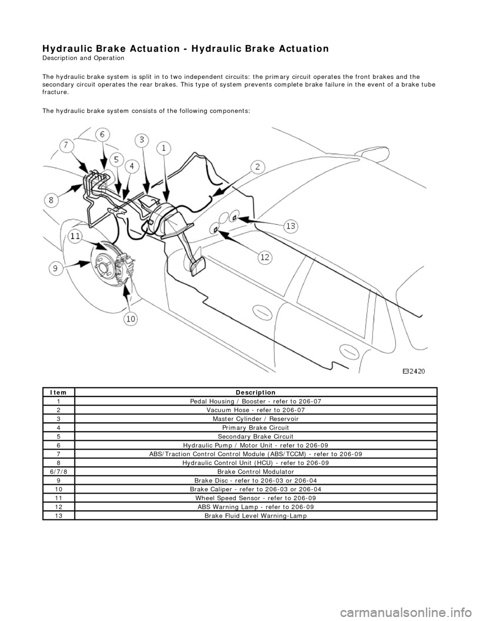
Hydraulic Br
ake Actuation -
Hydraulic Brake Actuation
Description and Operation
The hydraulic brake system is split in to two independent circuits: the primary ci rcuit operates the front brakes and the
secondary circuit operates the re ar brakes. This type of system prevents comple te brake failure in the event of a brake tube
fracture.
The hydraulic brake system consists of the following components:
Ite
m
Descr
iption
1Pedal Housi
ng / Booster - refer to 206-07
2Vacu
um Hose - refer to 206-07
3Mast
er Cyl
inder / Reservoir
4Primary Brake Circu
i
t
5Secon
dary Brake Circuit
6Hydrauli c
Pump / Motor Unit - refer to 206-09
7ABS/Traction
Control Control Modu
le (ABS/TCCM) - refer to 206-09
8Hydraulic Cont
rol Unit (HCU) - refer to 206-09
6/
7/
8
Br
ak
e Control Modulator
9Brake
Di
sc - refer to 206-03 or 206-04
10Brake
Cali
per - refer to 206-03 or 206-04
11W
h
eel Speed Sensor - refer to 206-09
12ABS Warning Lamp -
refer to 206
-09
13Brake F
l
uid Level Warning-Lamp
Page 429 of 2490
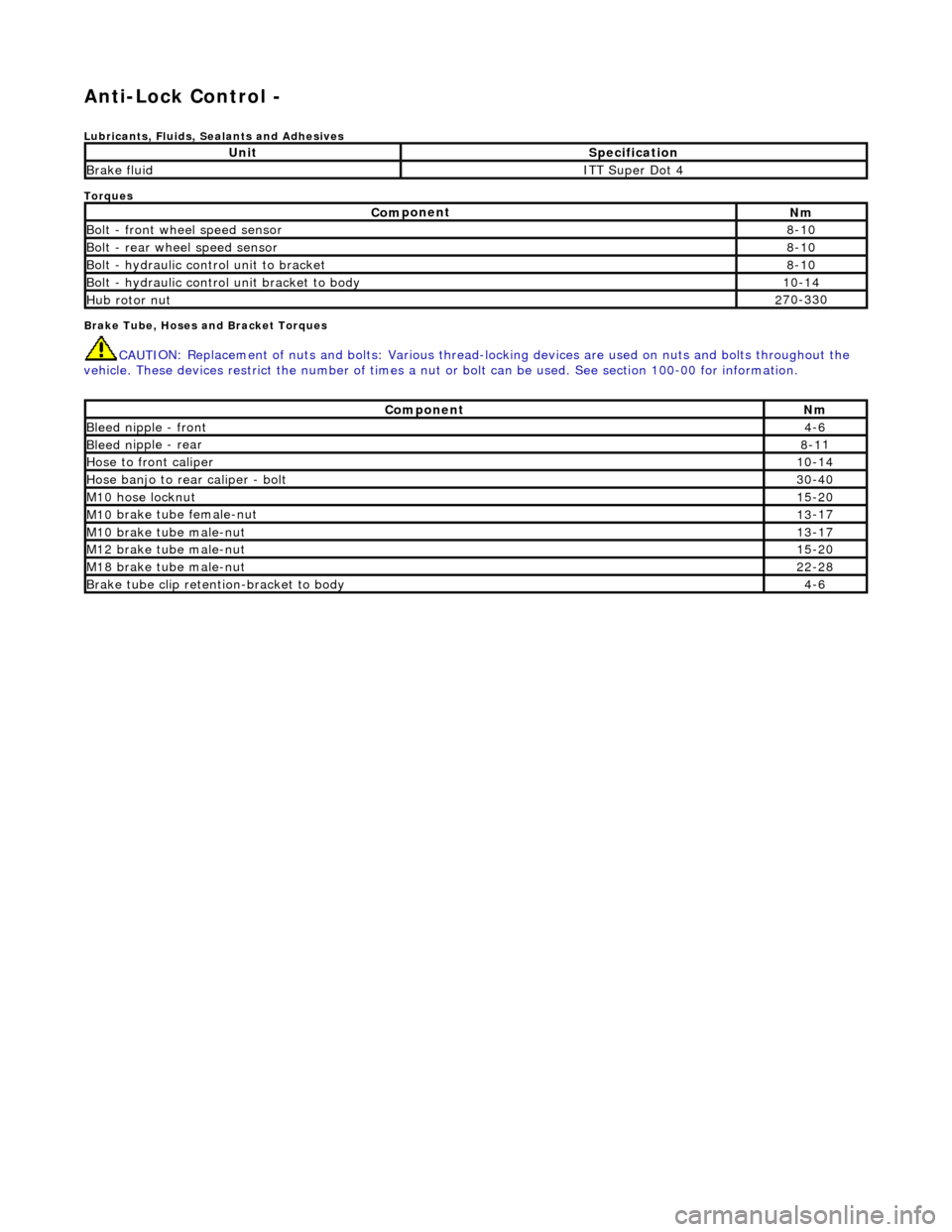
Anti-Lock Control -
Lubri
cants, Fluids, Sealants and Adhesives
Torques
Brake Tube, Hoses and Bracket Torques
CAUTI
ON: Replacement of
nuts and bolts: Various thread-locking devices are used on nuts and bolts throughout the
vehicle. These devices restrict the number of times a nut or bolt can be used. See section 100-00 for information.
UnitS
pecification
Brake flu
id
ITT Supe
r Dot 4
Com
ponent
Nm
Bol
t - front wheel speed sensor
8-
10
Bolt
- rear wheel speed sensor
8-
10
Bo
lt - hydraulic control unit to bracket
8-
10
Bolt -
hydraulic control unit bracket to body
10
-14
Hub rotor nut2
70-330
Com
ponent
Nm
Bleed n
ipple - front
4-
6
Bleed n
ipple - rear
8-1
1
Hose to fr
ont caliper
10
-14
Hose banjo to rear caliper -
bolt
30
-40
M1
0 hose locknut
15
-20
M10
brake tube female-nut
13
-17
M10
brake tube male-nut
13
-17
M12
brake tube male-nut
15
-20
M18
brake tube male-nut
22
-28
Brake tube clip retention
-bracket to body
4-
6
Page 430 of 2490
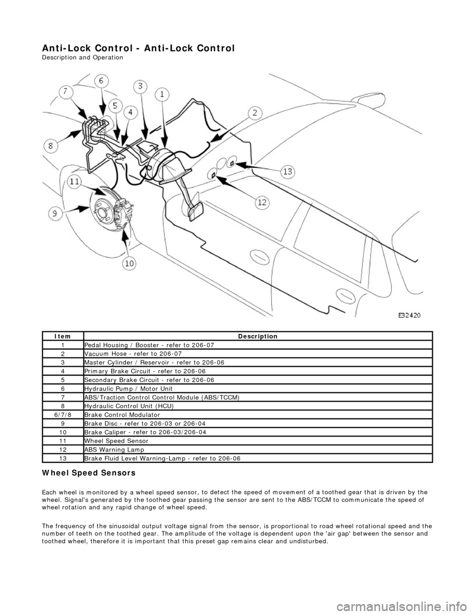
Anti-Lock Control - Anti-Lock Control
Description and Operation
Wheel Spe
ed Sensors
Each
wheel is monitored by a wheel speed se n
sor, to detect the speed of movement of
a toothed gear that is driven by the
wheel. Signal's generate d by the toothed gear passing th e sensor are sent to the ABS/TCCM to communicate the speed of
wheel rotation and any rapid change of wheel speed.
The frequency of the sinusoidal output voltag e signal from the sensor, is proportional to road wheel rotational speed and the
number of teeth on the toothed gear. The amplitude of the volt age is dependent upon the 'air gap' between the sensor and
toothed wheel, therefore it is important that this preset gap remains clear and undisturbed.
Ite
m
De
scr
iption
1Pe
dal Housi
ng / Booster - refer to 206-07
2Vac
u
um Hose - refer to 206-07
3Mas
t
er Cylinder / Reservoir - refer to 206-06
4Pri
m
ary Brake Circuit - refer to 206-06
5Sec
ondary Brake Circuit - refer to 206-06
6Hydraulic
Pump / Motor Unit
7ABS/Traction
Control Control Module (ABS/TCCM)
8Hydraulic Cont
rol Unit (HCU)
6/
7/
8
Br
ak
e Control Modulator
9Brake
Di
sc - refer to 206-03 or 206-04
10Brake
Cali
per - refer to 206-03/206-04
11Wh
ee
l Speed Sensor
12ABS Warning Lamp
13Brake
Fl
uid Level Warning-Lamp - refer to 206-06
Page 431 of 2490
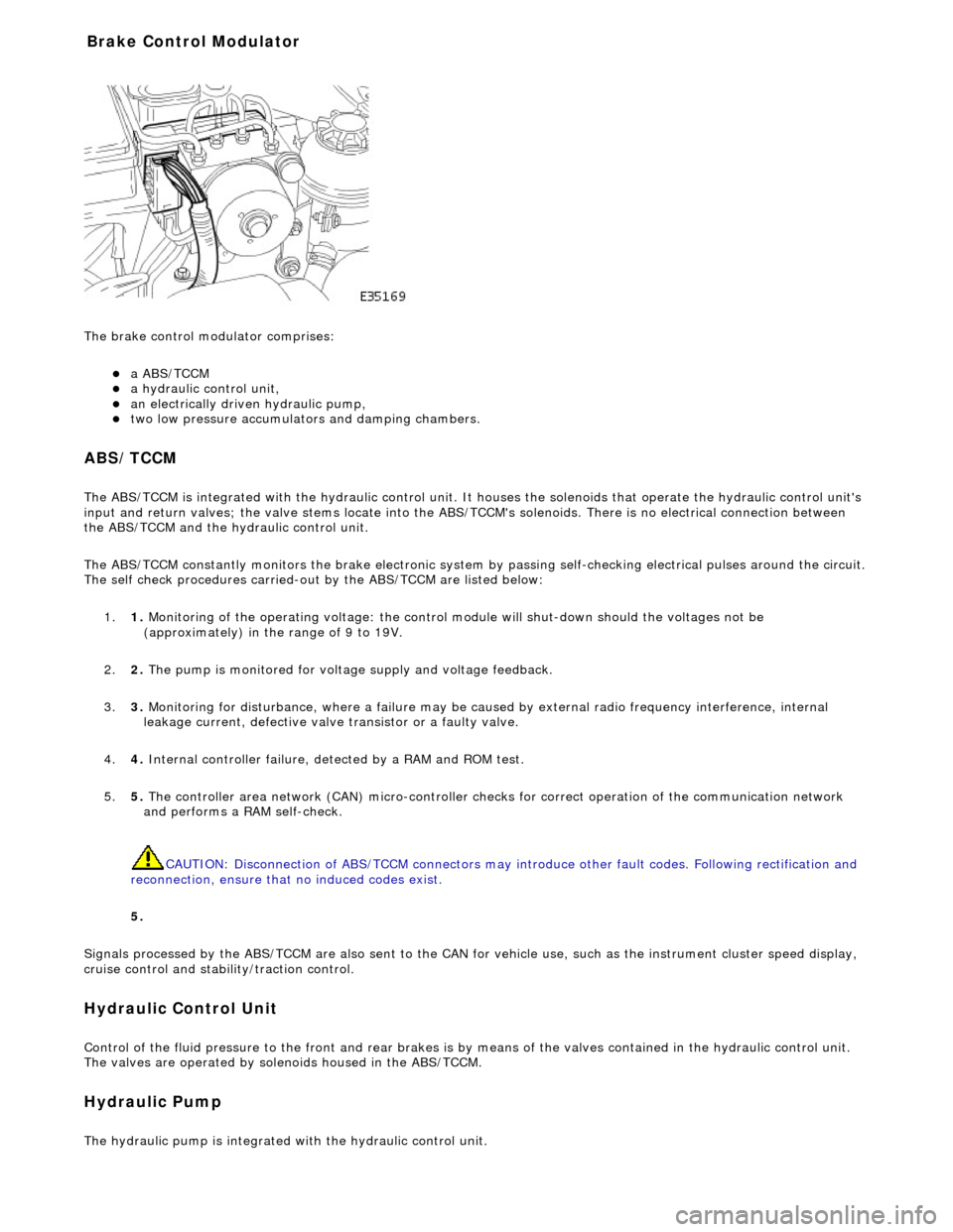
The brake
control modulator comprises:
a A
BS/TCCM
a h
ydraulic control unit,
an electrically driven hydrau
lic pump,
two low pressure accumulato
rs and damping chambers.
ABS/TCCM
The AB
S/TCCM is integrated with the hydrau
lic control unit. It houses the solenoids that operate the hydraulic control unit's
input and return valves; the valve stems locate into the ABS/TCCM's solenoids. There is no electrical connection between
the ABS/TCCM and the hydraulic control unit.
The ABS/TCCM constantly monitors the brake electronic system by passing self-checking electrical pulses around the circuit.
The self check procedures carried-out by the ABS/TCCM are listed below:
1. 1. Monitoring of the operating voltage: the control mo dule will shut-down should the voltages not be
(approximately) in the range of 9 to 19V.
2. 2. The pump is monitored for volt age supply and voltage feedback.
3. 3. Monitoring for disturbance, where a failure may be caus ed by external radio frequency interference, internal
leakage current, defective valve transistor or a faulty valve.
4. 4. Internal controller failure, de tected by a RAM and ROM test.
5. 5. The controller area network (CAN) micr o-controller checks for correct operation of the communication network
and performs a RAM self-check.
CAUTION: Disconnection of ABS/TCCM connectors may introduce other fault codes. Following rectification and
reconnection, ensure that no induced codes exist.
5.
Signals processed by the ABS/TCCM are also sent to the CAN for vehicle use, such as the instrument cluster speed display,
cruise control and stability/traction control.
Hydraulic Control Unit
Control of
the fluid pressure to
the front and rear brakes is by means of the valves contained in the hydraulic control unit.
The valves are operated by solenoids housed in the ABS/TCCM.
Hydraulic Pump
The
hydraulic pump is integrated
with the hydraulic control unit.
Bra
ke Control Modulator
Page 432 of 2490
It is a reciprocating two
-circuit pu
mp in which one brake circuit is as signed to each pump circuit.
It supplies th
e fluid pressure and vo
lume to supply the brake circuits under ABS and Traction control.
The pump is driven by an electri
c motor, with the pump
housing incorporating two lo w pressure accumulators and
damping chambers for each brake circuit.
The ac cu
mulator stores the pressure and smooths out the output pu
lses from the pump.
ABS Warning Lamp
The sys
tem will be set in a fail-safe mode if a problem is de
tected; a warning lamp on the instrument panel will notify the
driver there is a problem.
Anti-Lock Braking Sy
stem (ABS)
The AB
S components are combined with
an hydraulic booster and a tandem master cylinder to provide a two circuit braking
system. The system comprises, four wheel speed sensor s, a brake control modulator and an ABS warning lamp.
Should a wheel start to lock-up during braking a signal tr ansmitted from the wheel speed sensor to the brake control
modulator will start the hydraulic pump. The brake control modula tor will close the input valve of the line connected to the
locked-wheel to stop any increase in fluid pressure to the br ake caliper. If this fails to prevent the wheel locking, the
pressure in the caliper will be decreased by opening the return valve until th e wheel starts accelerating again. The fluid
pressure from the return va lve is directed into the low pressure accumulator, housed in the pump.
From the low pressure accumulator, fl uid is pumped through the damping cham ber to the brake master cylinder. The
pressure to the brake caliper will then be increased in small steps to maintain maximum adhesion between the tire and road
surface. This is achieved by closing the return valve, and opening the input valve and using the hydraulic pump to increase
the pressure.
Although the system senses all four wheels independently, the rear wheels are regulated as a pair. If a sensor on a rear
wheel detects a wheel decelerating rapidly, then the fluid pressure to both wheels is reduced. The fluid pressure is then
dictated by the wheel having the lowe st adhesion with the road surface.
The ABS system will be set in a fail-safe mode if a problem is detected; a warn ing lamp on the instrument panel will notify
the driver there is a problem. The brake system will still operate conventionally and with the same standard of performance
as a vehicle not equipped with ABS.
Automa tic Stability Control (ASC)
Th
e ASC utilizes the ABS sensing arrangement to provide the maximum traction force to propel the vehicle.
The ASC is switched on when the engine is started. The system can be switched off by pressing the 'ASC OFF' (the switched
is marked 'TRAC OFF' on vehicles fitted with traction control). The switch, which is situated in the center console switchpack,
lights up to warn that the system is sw itched off. An 'ASC' amber warning light flashes on the instrument panel when the
system detects a spinning wheel.
The ASC system uses engine intervention to reduce the torque delivered to the drive wheels to prevent them spinning.
Engine torque is re duced in three ways:
The
throttle is moved towards the closed position.
The ignition is retarded. F
u
el is cut-off at the cylinder injectors.
Wheel spin is detected by the wheel sp eed sensors and communicated to the AB S/TCCM. The ABS/TCCM uses information
from the controller area network (CAN) to calculate the torque that the engine should produce to stop the wheel spinning.
Torque reductions are then requested from the engine control module (ECM ) through the CAN. The throttle is then
positioned to provide the target torque, which has been calculated to prevent wheel spin. During the transient phase of
torque reduction the fuel is cut-off and th e ignition retarded Both the fuel cut-off an d ignition retard will be restored to
normal when the throttle is set to its new position.
The ASC uses a brake control modulator with six solenoid va lves: three normally open inlet valves and three normally
Page 433 of 2490
clos
ed outlet valves.
Traction Control
Trac
tion control has the same capabilities as ASC but with th
e added ability to actuate the brakes of the spinning wheel.
This enhances ASC by improving acceleration particularly on surfaces with uneven friction , e.g. one wheel on ice the other
on tarmac.
When wheelspin occurs, brake line pressure to the slipping wheel is generated, to operate that wheel's brake. The BCM
achieves this by closing the cut-off solenoid valve and oper ating the hydraulic pump. Brake fluid is then drawn from the
reservoir through the non-actuated mast er cylinder to the brake caliper.
A 'TRAC' amber warning light flashes on the instrument panel when the system detects a spinning wheel.
The traction control system uses a brake control modulator with nine solenoid valv es: four normally open inlet valves and
four normally closed outlet valves and one special isolating va lve. The outlet valves control the brakes of each each rear
wheel individually on the traction control system.
Rear Wheel Speed Senso
rs and ABS/TCCM Circuit Diagram