speed control JAGUAR X308 1998 2.G Owner's Manual
[x] Cancel search | Manufacturer: JAGUAR, Model Year: 1998, Model line: X308, Model: JAGUAR X308 1998 2.GPages: 2490, PDF Size: 69.81 MB
Page 435 of 2490
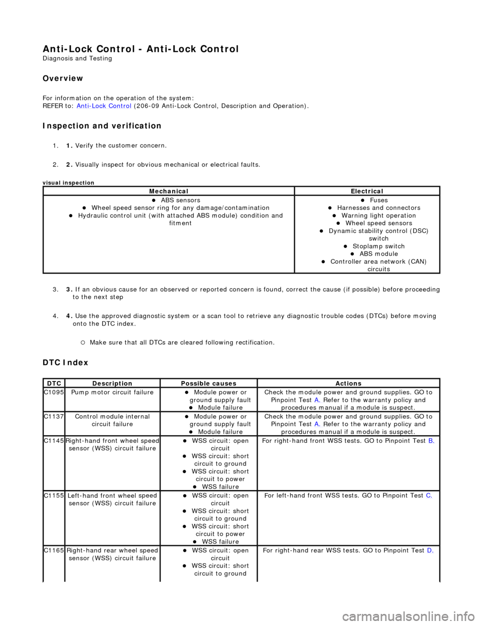
Anti-Lock Control - Anti-Lock Control
D
iagnosis and Testing
Ov
erview
Fo
r information on the operation of the system:
REFER to: Anti
-Lock Control
(206-09 Anti-Lock Control, Description and Operation).
I
nspection and verification
1.
1. Veri
fy the customer concern.
2. 2. Visually inspect for obvious mech anical or electrical faults.
visual insp
ection
3.
3. If
an obvious cause for an observed or
reported concern is found, correct th e cause (if possible) before proceeding
to the next step
4. 4. Use the approved diagnostic system or a scan tool to retrieve any diagnostic trouble codes (DTCs) before moving
onto the DTC index.
Make sure that
all DTCs are cleared following rectification.
DTC Index
MechanicalElectrical
ABS se
nsors
W
heel speed sensor ring for
any damage/contamination
Hydrauli
c control unit (with attached ABS module) condition and
fitment
F
uses
Harnes
ses and connectors
War
ning light operation
Wh
eel speed sensors
Dynam
ic stability control (DSC)
switch
Stoplamp switch
ABS module Con
troller area network (CAN)
circuits
DT
C
De
scription
Possib
le causes
Acti
ons
C1
095
Pump mo
tor circuit failure
Module power or
gr
ound supply fault
Module
failure
Check the modu
le power and
ground supplies. GO to
Pinpoint Test A.
R
efer to the warranty policy and
procedures manual if a module is suspect.
C1
137
Control modu
le internal
circuit failure
Module power or
gr
ound supply fault
Module
failure
Check the modu
le power and
ground supplies. GO to
Pinpoint Test A.
R
efer to the warranty policy and
procedures manual if a module is suspect.
C1
145
Right
-hand front wheel speed
sensor (WSS) circuit failure
W
SS circuit: open
circuit
W
SS circuit: short
circuit to ground
W
SS circuit: short
circuit to power
WSS
failure
F
or right-hand front WSS tests. GO to Pinpoint Test
B.
C1
155
Left-hand front wheel
speed
sensor (WSS) circuit failure
W
SS circuit: open
circuit
W
SS circuit: short
circuit to ground
W
SS circuit: short
circuit to power
WSS
failure
F
or left-hand front WSS tests. GO to Pinpoint Test
C.
C1
165
Ri
ght-hand rear wheel speed
sensor (WSS) circuit failure
W
SS circuit: open
circuit
W
SS circuit: short
circuit to ground
F
or right-hand rear WSS test
s. GO to Pinpoint Test D.
Page 437 of 2490
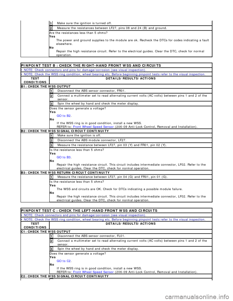
Make sure the ignition is turned off. 1
Meas
ure the resistances between LF27,
pins 08 and 24 (B) and ground.
2
Are
the resistances less than 5 ohms?
Yes The power and ground supplies to the module are ok . Recheck the DTCs for codes indicating a fault
elsewhere.
No Repair the high resistance circui t. Refer to the electrical guides. Clear the DTC, check for normal
operation.
PINPOINT TE
ST B : CHECK THE RIGHT-HAND FRONT WSS AND CIRCUITS
•
NOTE: Check connectors and pins for damage/corrosion
(see visual inspection).
•
NOTE: Check the WSS ring condition, whee
l bearing etc. Before beginning pinpoint test s refer to the visual inspection.
TE
ST
CONDITIONS
D
ETAILS/RESULTS/ACTIONS
B1: CHECK
THE WSS OUTPUT
Disc
onnect the ABS sensor connector, FR01.
1
Connec
t a multimeter set
to read alternating curr ent volts (AC volts) between pins 1 and 2 of the
sensor.
2
Spin
the wheel by hand and check the meter display.
3
Doe
s the sensor generate a voltage?
Yes GO to B2
.
No
If the WSS ring is in good condition, install a new WSS.
REFER to: Front Wheel Speed Sensor
(20
6-09 Anti-Lock Control, Removal and Installation).
B2:
CHECK THE WSS SIGNAL CIRCUIT CONTINUITY
Make sure the ignition is off. 1
Di
sconnect the ABS module connector, LF27.
2
Meas
ure the resistance between LF27
, pin 03 (Y) and FR01, pin 02 (Y).
3
I
s the resistance less than 5 ohms?
Yes GO to B3
.
No
Repair the high resistance circui t. This circuit includes intermediate connector, LF02. Refer to the
electrical guides. Clear the DTC, check for normal operation.
B3:
CHECK THE WSS RETURN CIRCUIT CONTINUITY
Meas
ure the resistance between LF27
, pin 04 (G) and FR01, pin 01 (G).
1
I
s the resistance less than 5 ohms?
Yes The WSS and circuits are OK. Check for DTCs indicating a possible module failure.
No Repair the high resistance circui t. This circuit includes intermediate connector, LF02. Refer to the
electrical guides. Clear the DTC, check for normal operation.
P
INPOINT TEST C : CHECK THE LEFT-HAND FRONT WSS AND CIRCUITS
•
NOTE: Check connectors and pins for damage/corrosion
(see visual inspection).
•
NOTE: Check the WSS ring condition, whee
l bearing etc. Before beginning pinpoint test s refer to the visual inspection.
TE
ST
CONDITIONS
D
ETAILS/RESULTS/ACTIONS
C1
: CHECK THE WSS OUTPUT
Disc
onnect the ABS sensor connector, FL01.
1
Connec
t a multimeter set
to read alternating curr ent volts (AC volts) between pins 1 and 2 of the
sensor.
2
Spin
the wheel by hand and check the meter display.
3
Doe
s the sensor generate a voltage?
Yes GO to C2
.
No
If the WSS ring is in good condition, install a new WSS.
REFER to: Front Wheel Speed Sensor
(20
6-09 Anti-Lock Control, Removal and Installation).
C2
: CHECK THE WSS SIGNAL CIRCUIT CONTINUITY
Page 438 of 2490
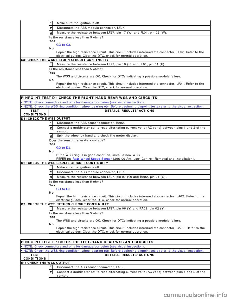
Make sure the ignition is off. 1
Disc
onnect the ABS module connector, LF27.
2
M
e
asure the resistance between LF27, pin 17 (W) and FL01, pin 02 (W).
3
I
s
the resistance less than 5 ohms?
Yes GO to C3
.
No
Re
pair the high resistance circui
t. This circuit includes intermed iate connector, LF02. Refer to the
electrical guides. Clear the DTC, check for normal operation.
C3: CH
ECK THE WSS RETURN CIRCUIT CONTINUITY
Measure
the resistance between LF27, pin 18 (R) and FL01, pin 01 (R).
1
Is
the resistance less than 5 ohms?
Yes The WSS and circuits are OK. Check for DTCs indicating a possible module failure.
No Repair the high resistance circui t. This circuit includes intermediate connector, LF01. Refer to the
electrical guides. Clear the DTC, check for normal operation.
PI
NPOINT TEST D : CHECK THE RIGH
T-HAND REAR WSS AND CIRCUITS
•
NOTE: Check connectors and pins for damage/corrosion
(see visual inspection).
• NO
TE: Check the WSS ring condition, whee
l bearing etc. Before beginning pinpoint test s refer to the visual inspection.
TES
T
CONDITIONS
D E
TAILS/RESULTS/ACTIONS
D1: CHECK
THE WSS OUTPUT
Disc
onne
ct the ABS sensor connector, RA02.
1
Connec
t
a multimeter set
to read alternating curr ent volts (AC volts) between pins 1 and 2 of the
sensor.
2
Spin
the wheel by hand and check the meter display.
3
Doe
s
the sensor generate a voltage?
Yes GO to D2
.
No
If
the WSS ring is in good condition, install a new WSS.
REFER to: Rear Wheel Speed Sensor
(206-0
9 Anti-Lock Control, Removal and Installation).
D
2
: CHECK THE WSS SIGNAL CIRCUIT CONTINUITY
Make sure the ignition is off. 1
Disc
onnect the ABS module connector, LF27.
2
Measure t
he resistance between LF27
, pin 07 (O) and RA02, pin 01 (O).
3
Is
the resistance less than 5 ohms?
Yes GO to D3
.
No Re
pair the high resistance circui
t. This circuit includes intermed iate connector, LA02. Refer to the
electrical guides. Clear the DTC, check for normal operation.
D3:
CHECK THE WSS RETURN CIRCUIT CONTINUITY
Meas
ure t
he resistance between LF27
, pin 06 (Y) and RA02, pin 02 (Y).
1
Is
the resistance less than 5 ohms?
Yes The WSS and circuits are OK. Check for DTCs indicating a possible module failure.
No Repair the high resistance circui t. This circuit includes intermediate connector, CA09. Refer to the
electrical guides. Clear the DTC, check for normal operation.
PI
NPOINT TEST E : CHECK THE LEFT-HAND REAR WSS AND CIRCUITS
•
NOTE: Check connectors and pins for damage/corrosion
(see visual inspection).
• NO
TE: Check the WSS ring condition, whee
l bearing etc. Before beginning pinpoint test s refer to the visual inspection.
TES
T
CONDITIONS
D E
TAILS/RESULTS/ACTIONS
E1
: CHECK THE W
SS OUTPUT
Disc
onne
ct the ABS sensor connector, LA02.
1
Connec
t
a multimeter set
to read alternating curr ent volts (AC volts) between pins 1 and 2 of the
sensor.
2
Page 439 of 2490
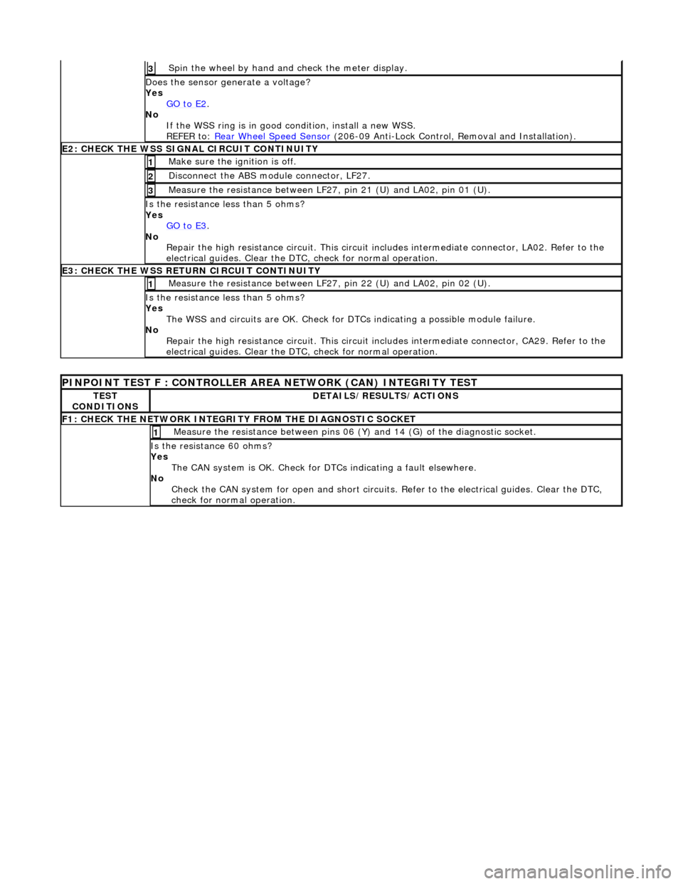
Spin
the wheel by hand and check the meter display.
3
Doe
s the sensor generate a voltage?
Yes GO to E2
.
No
If the WSS ring is in good condition, install a new WSS.
REFER to: Rear Wheel Speed Sensor
(20
6-09 Anti-Lock Control, Removal and Installation).
E2
: CHECK THE WSS SIGNAL CIRCUIT CONTINUITY
Make sure the ignition is off. 1
Di
sconnect the ABS module connector, LF27.
2
Meas
ure the resistance between LF27
, pin 21 (U) and LA02, pin 01 (U).
3
I
s the resistance less than 5 ohms?
Yes GO to E3
.
No
Repair the high resistance circui t. This circuit includes intermediate connector, LA02. Refer to the
electrical guides. Clear the DTC, check for normal operation.
E3
: CHECK THE WSS RETURN CIRCUIT CONTINUITY
Meas
ure the resistance between LF27
, pin 22 (U) and LA02, pin 02 (U).
1
I
s the resistance less than 5 ohms?
Yes The WSS and circuits are OK. Check for DTCs indicating a possible module failure.
No Repair the high resistance circui t. This circuit includes intermediate connector, CA29. Refer to the
electrical guides. Clear the DTC, check for normal operation.
P
INPOINT TEST F : CONT
ROLLER AREA NETWORK (CAN) INTEGRITY TEST
TE
ST
CONDITIONS
D
ETAILS/RESULTS/ACTIONS
F
1: CHECK THE NETWORK INTEGRITY
FROM THE DIAGNOSTIC SOCKET
M
easure the resistance between pins 06 (Y) and 14 (G) of the diagnostic socket.
1
I
s the resistance 60 ohms?
Yes The CAN system is OK. Check for DTCs indicating a fault elsewhere.
No Check the CAN system for open an d short circuits. Refer to the electrical guides. Clear the DTC,
check for normal operation.
Page 444 of 2490

Anti-Lock Control - Front Wheel Speed Sensor
Remo
val and Installation
Remov
a
l
Installation
1.
Ra
ise front of vehicle and support
on stands. Refer to section
100-02.
2. Remove wh
eel speed sensor.
Di
sc
onnect harness connector.
Re
mo
ve bolt.
3. Clean components and mating surfaces.
1. Inst al
l wheel speed sensor.
Posit
i
on sensor.
Install and tigh
ten bolt to 8-1
0 Nm.
Conne
ct
harness connector.
2. Remove stands an d lower vehicle.
Page 449 of 2490

Anti-Lock Control - Rear Wheel Speed Sensor
Re
moval and Installation
Remov
al
Installation
1.
R
aise rear of vehicle and support
on stands. Refer to section
100-02.
2. Re
move wheel speed sensor.
Di
sconnect harness connector.
Re
move bolt.
3. Clean components and mating surfaces.
1. Inst
all wheel speed sensor.
Posit
ion sensor.
Install and tigh
ten bolt to 8-10 Nm.
Conne
ct harness connector.
2. Remove stands an d lower vehicle.
Page 450 of 2490

Anti-Lock Control - Wheel Speed Se
nsor Ring
Re
mo
val and Installation
Remov
a
l
CAUTI
O
N: Replacement of
nuts and bolts: Various thread-locking devices are used on nuts and bolts throughout the
vehicle. These devices restrict the number of times a nut or bolt can be used. See section 100-00 for information.
S p
ecial Tool(s)
Hub Holdin
g Tool
2
04-195 (JD 227)
ABS Rotor Nut Socket
2
06-
066A
1.
Op
en engine compartment and
fit paintwork protectors to
fenders.
2. Raise front of vehicle and support on stands. Refer to section
100-02.
3. Remove front wheel. Re fer to section 204-04.
4. Remove front brake disc. Refer to operation 70.10.12.
5. Remove vertical link and hub assembly. Refer to operation
60.25.38.90.
6. Re
move brake-disc shield from vertical link.
1. Remove screws.
2. Remove disc shield.
7. Using special tool, secure vertical link and hub assembly in a
vice.
Secure special tool
in a vice.
Posit
i
on hub in tool.
Fit and
tighten wheel nuts.
Page 455 of 2490
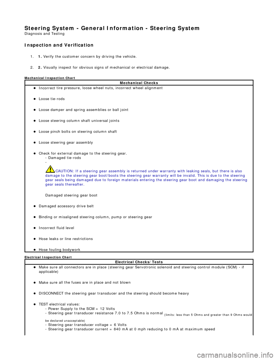
Steering System - General Inform
ation - Steering System
D
iagnosis and Testing
I
nspection and Verification
1.
1. Verify t
he customer concern by driving the vehicle.
2. 2. Visually inspect for obvious signs of mechanical or electrical damage.
Mec
hanical Inspection Chart
Electrical Inspection Chart
Mechanical Checks
Incorrect
tire pressure, loose whee
l nuts, incorrect wheel alignment
Loose ti
e-rods
Loose dam
per and spring assemblies or ball joint
Loose s
teering column shaft universal joints
Loose pinc
h bolts on steering column shaft
Loose steeri
ng gear assembly
Check f
or external damage to the steering gear.
- Damaged tie-rods
-
CAUTION: If a steering gear assemb ly is returned under warranty with leaking seals, but there is also
damage to the steering gear boot/boots the steering gear warranty will be invalid. This is due to the steering
gear seals being damaged due to fore ign materials entering the steering gear boot and damaging the steering
gear seals thereafter.
Damaged steering gear boot
Damaged accessory driv
e belt
Bin
ding or misaligned steering co
lumn, pump or steering gear
Incorrect fluid
level
Hose leaks o
r line restrictions
Hose fou
ling bodywork
El
ectrical Checks/Tests
Make sure all
connectors are in plac
e (steering gear Servotronic solenoid and steering control module (SCM) - if
applicable)
Make su
re all the fuses are in place and not blown
D
ISCONNECT the steering gear transducer
and the steering should become heavy
TEST e
lectrical values:
- Power Supply to the SCM = 12 Volts
- Steering gear transducer resist ance 7.0 to 7.5 Ohms is normal
(
limits: less than 5 Ohms and greater than 9 Ohms would
be declared unacceptable)
- Steeri
ng gear transducer voltage = 6 Volts
- Steering gear transducer cu rrent = 840 mA at 0 mph reducing to 0 mA at maximum speed
Page 458 of 2490
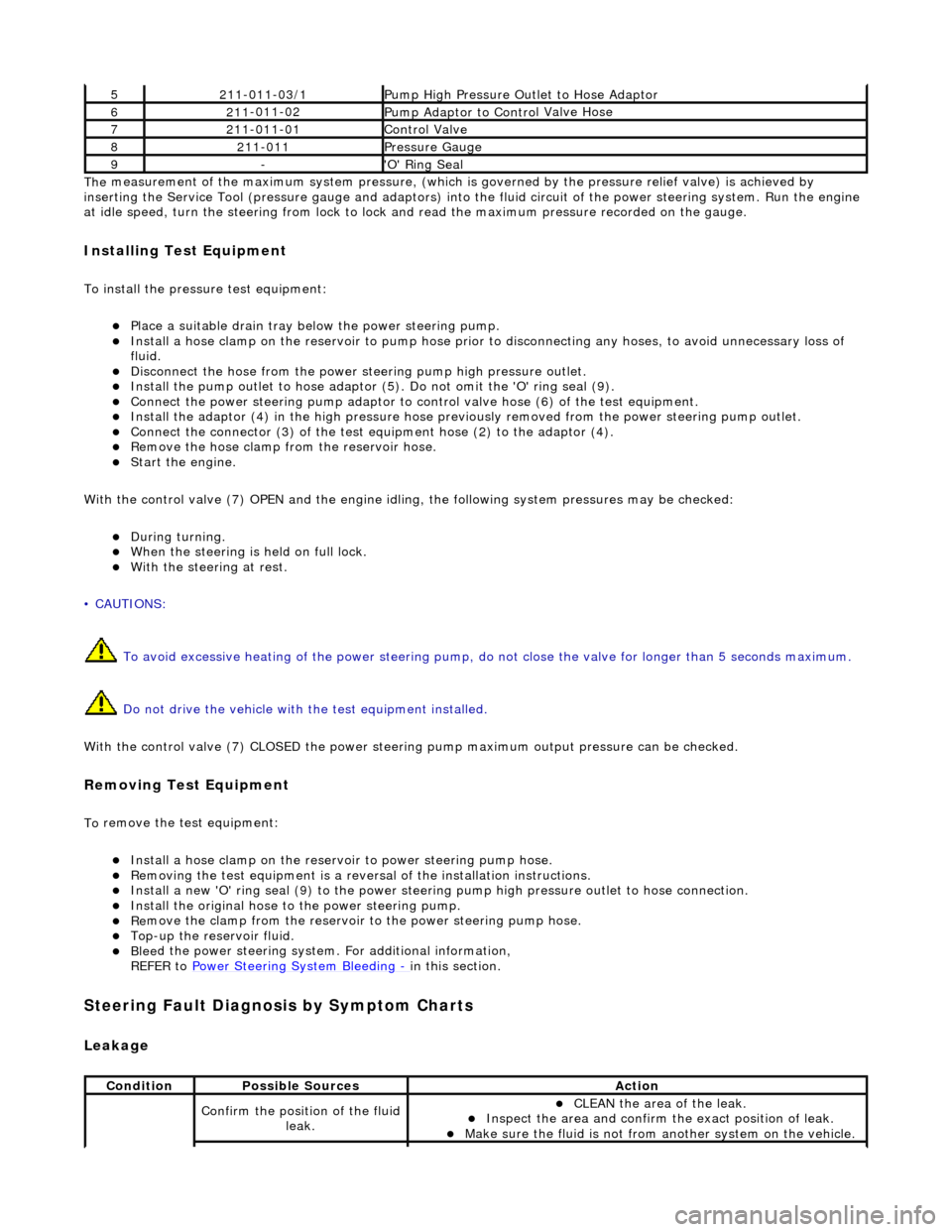
The
measurement of the maximum system pressure, (which is
governed by the pressure relief valve) is achieved by
inserting the Service Tool (pressure gauge and adaptors) into th e fluid circuit of the power steering system. Run the engine
at idle speed, turn the st eering from lock to lock and read the ma ximum pressure recorded on the gauge.
Installin
g Test Equipment
To
in
stall the pressure test equipment:
Pla
c
e a suitable drain tray be
low the power steering pump.
Install a hose clamp on
the re
servoir to pump hose prior to disconnecting any hoses, to avoid unnecessary loss of
fluid.
Disc
onnect the hose from the power st
eering pump high pressure outlet.
Install the pu
mp outlet to hose adaptor (5
). Do not omit the 'O' ring seal (9).
Connect the power steering
pump
adaptor to control valve hose (6) of the test equipment.
Install th e adaptor (4) in th
e high
pressure hose previously removed from the power steering pump outlet.
Conn
ect the connector (3) of the test equipment hose (2) to the adaptor (4).
R
e
move the hose clamp fro
m the reservoir hose.
Start th
e engine.
With the control valve (7) OPEN and the engine idli ng, the following system pressures may be checked:
Du
ring turning.
W
h
en the steering is
held on full lock.
With
the steeri
ng at rest.
• CAUTIONS:
To avoid excessive heating of the po wer steering pump, do not close the valve for longer than 5 seconds maximum.
Do not drive the vehicle with the test equipment installed.
With the control valve (7) CLOSED the power steering pump maximum ou tput pressure can be checked.
Removing Test Equipment
To
remove the test equipment:
Install a hose clamp
on
the reservoir to power steering pump hose.
Re
movi
ng the test equipmen
t is a reversal of the in stallation instructions.
Install a new '
O
' ring seal (9) to the power steering pump high pressu
re outlet to hose connection.
Instal
l the original hose to
the power steering pump.
Re
move the clamp from the reservoir to
the power steering pump hose.
Top-up the reservoir flui
d.
Ble
e
d the power steerin
g system. For additional information,
REFER to Power Steering System Bleeding
- in thi
s section.
Stee
ring Fault Diagnosis by Sympt
om Charts
Leakage
52
11-0
11-03/1
Pump High Pressure Ou
tlet
to Hose Adaptor
621
1
-011-02
Pump Adaptor
to Contro
l Valve Hose
721
1
-011-01
Control Valve
82
11-
011
Pressure Gauge
9-'O
'
Ring Seal
Cond
iti
on
Possib
l
e Sources
Acti
o
n
Co
nfirm
the position of the fluid
leak.
CLEAN th
e area of the leak.
In
s
pect the area and confirm the exact position of leak.
Make sure the fluid
is not from anoth
er system on
the vehicle.
Page 462 of 2490
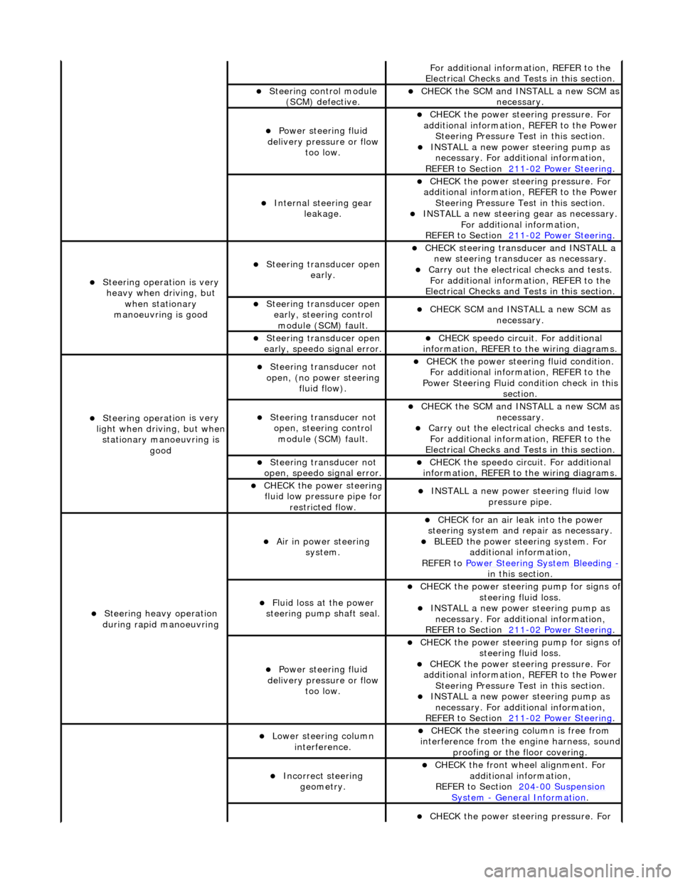
Fo
r additional information, REFER to the
Electrical Checks and Tests in this section.
Steering control
module
(SCM) defective.
CHECK
the SCM and INSTALL a new SCM as
necessary.
Power steeri ng f
luid
delivery pressure or flow too low.
CHECK
the power stee
ring pressure. For
additional information, REFER to the Power Steering Pressure Test in this section.
INSTALL a ne
w power steering pump as
necessary. For additi onal information,
REFER to Section 211
-0 2
Power Steering
.
Internal steering gear
leakage.
CHECK
the power stee
ring pressure. For
additional information, REFER to the Power Steering Pressure Test in this section.
INSTALL a ne
w steering
gear as necessary.
For additional information,
REFER to Section 211
-0 2
Power Steering
.
Steeri
ng operati
on is very
heavy when driving, but when stationary
manoeuvring is good
Steering transducer open earl
y.
CHECK
steering transducer and INSTALL a
new steering transducer as necessary.
Carry out th
e electrical checks and tests.
For additional information, REFER to the
Electrical Checks and Tests in this section.
Steering transducer open
early,
steering control
module (SCM) fault.
CHECK
SCM and INSTALL a new SCM as
necessary.
Steering transducer open
earl
y, speedo signal error.
CHECK
speedo
circui
t. For additional
information, REFER to the wiring diagrams.
Steeri ng operati
on is very
light when driving, but when
stationary manoeuvring is good
Steering transducer not
o
pen, (no power steering
fluid flow).
CHECK
the power steering fluid condition.
For additional information, REFER to the
Power Steering Fluid condition check in this section.
Steering transducer not o
pen, steering control
module (SCM) fault.
CHECK
the SCM and INSTALL a new SCM as
necessary.
Carry out th
e electrical checks and tests.
For additional information, REFER to the
Electrical Checks and Tests in this section.
Steering transducer not
o
pen, speedo signal error.
CHECK
the speedo circ
uit. For additional
information, REFER to the wiring diagrams.
CHECK
the power steering
fluid low pressure pipe for restricted flow.
INSTALL a ne
w power steering fluid low
pressure pipe.
S t
eering heavy operation
during rapid manoeuvring
Ai r i
n power steering
system.
CHECK for an air l
eak into the power
steering system and re pair as necessary.
BLEED the
power steering system. For
additional information,
REFER to Power Steering System Bleeding
- in t hi
s section.
Fluid loss at the power
steering pump shaft seal.
CHECK the power steer
ing pump for signs o
f steering fl
ui
d loss.
INST
ALL a ne
w power steering pump as
necessary. For additi onal information,
REFER to Section 211
-0 2
Power Steering
.
Power steeri
ng f
luid
delivery pressure or flow too low.
CHECK the power steer
ing pump for signs o
f steering fl
ui
d loss.
CHECK
the power stee
ring pressure. For
additional information, REFER to the Power Steering Pressure Test in this section.
INSTALL a ne
w power steering pump as
necessary. For additi onal information,
REFER to Section 211
-02
Power Steering
.
Lower steeri
ng col
umn
interference.
CHECK
the steering co
lumn is free from
interference from the en gine harness, sound
proofing or the floor covering.
Incorrect steering geometry. CHE
CK the front wheel alignment. For
additional information,
REFER to Section 204
-00 Sus
pension
Sy
ste
m
- General
Information
.
CHECK
the power stee
ring pressure. For