Seat JAGUAR X308 1998 2.G Workshop Manual
[x] Cancel search | Manufacturer: JAGUAR, Model Year: 1998, Model line: X308, Model: JAGUAR X308 1998 2.GPages: 2490, PDF Size: 69.81 MB
Page 2113 of 2490

Rear View Mirrors - Auto-Dimming Interior Mirror
Removal and Installation
Removal
Installation
1.
Remove roof console for access and disconnect interior mirror
harness multiplugs. Refer to 76.13.69.90.
2. Remove upper cover from mirror stem.
3. Remove rain sensor unit. Refer to Section 501.16.
4. CAUTION: When removing mirror from base, care must
be exercised to ensure that base is not detached from windshield.
Applying firm downward pre ssure, remove mirror assembly
from base.
1. Position mirror at bottom of base and apply firm upward
pressure to fully seat and secure in position.
2. Install upper cover to mirror stem.
3. Position roof console at head er and connect mirror harness
multiplugs.
4. Install rain sensor unit. Refer to Section 501.16.
5. Install roof console. Refer to 76.13.69.
Page 2114 of 2490
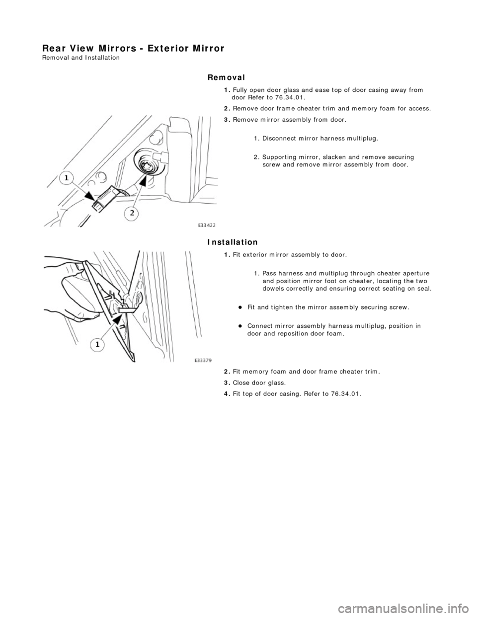
Rear View Mirrors - Exterior Mirror
Removal and Installation
Removal
Installation
1.
Fully open door glass and ease top of door casing away from
door Refer to 76.34.01.
2. Remove door frame cheater trim and memory foam for access.
3. Remove mirror assembly from door.
1. Disconnect mirror harness multiplug.
2. Supporting mirror, slacken and remove securing screw and remove mirror assembly from door.
1. Fit exterior mirror assembly to door.
1. Pass harness and multiplu g through cheater aperture
and position mirror foot on cheater, locating the two
dowels correctly and ensuring correct seating on seal.
Fit and tighten the mirror assembly securing screw.
Connect mirror assembly harness multiplug, position in
door and reposition door foam.
2. Fit memory foam and door frame cheater trim.
3. Close door glass.
4. Fit top of door casing. Refer to 76.34.01.
Page 2115 of 2490

Rear View Mirrors - Exterior Mirror Cover
Removal and Installation
Removal
Installation
1.
Remove exterior mirror glass. Refer to 76.10.53.
2. Remove exterior mirror cap.
1. From housing interior, pr ess out the three cap dowels
complete with securing clips.
Remove mirror cap from casing.
Remove and discard the securing clips.
1. Fit cap to mirror housing.
1. Fit and fully seat new cap securing clips in mirror base.
2. Align mirror cap dowels with the securing clips and press firmly into place.
2. Fit mirror glass. Refer to 76.10.53.
Page 2118 of 2490

Rear View Mirrors - Interior Mirror
Removal and Installation
Removal
CAUTION: When removing mirror from base, care must be exercised to ensure that base is not detached from
windshield.
Installation
1. Remove upper cover from mirror stem.
2. Remove rain sensor unit. Refer to Section 501.16.
3. Applying firm downward pre ssure, remove mirror assembly
from base.
1. Position mirror at bottom of base and apply firm upward
pressure to fully seat and secure in position.
2. Install rain sensor unit. Refer to Section 501.16.
3. Install upper cover to mirror stem.
Page 2121 of 2490
Seating - Seats Description and Operation
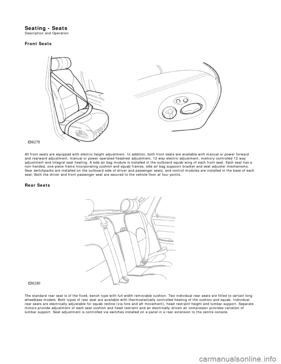
Front Seats
All front seats are equipped with electric height adjustment. In addition, both front seats are available with manual or power forward
and rearward adjustment, manual or powe r operated headrest adjustment, 12 way elec tric adjustment, memory controlled 12 way
adjustment and integral seat heating. A side air bag module is installed in the outboard squab wing of each front seat. Each se at has a
non-handed, one-piece frame incorporating cushion and squab frames , side air bag suppoort bracket and seat adjuster mechanisms.
Sear switchpacks are installed on the outboa rd side of driver and passenger seats, and control modules are installed in the bas e of each
seat. Both the driver and front passenger seat ar e secured to the vehicle floor at four points.
Rear Seats
The standard rear seat is of the fixed, bench type with full wi dth removable cushion. Two individual rear seats are fitted to certain long
wheelbase models. Both types of rear seat are available with thermostatically controlled heating of the cushion and squab. Indi vidual
rear seats are electrically adjustable for squab recline (via fore and aft moveme nt), head restraint height and lumbar support. Separate
motors provide adjustment of each seat cushion and head restraint and an electrica lly-driven air compressor provides variation of
lumbar support. Seat adjustment is controll ed via switches installed on a panel in a rear extension to the centre console.
Page 2122 of 2490

Seating - Front Seat
Removal and Installation
Removal
1. Move the seat fully rearward and slacken and remove the
front securing bolts.
2. Move steering wheel to fully forward position.
3. Ensure that squab is fully upright, then move the seat fully
forward.
4. WARNING: FOLLOWING DISCONNECTION OF THE
BATTERY A PERIOD OF AT LEAST ONE MINUTE MUST BE
ALLOWED TO ELAPSE BEFORE WORKING ON A FRONT SEAT WITH
A SIDE AIRBAG FITTED.
Remove battery cover and disc onnect ground cable from
battery terminal. Refer to 86.15.19.
5. Remove the slider covers an d slacken and remove the two
rear securing bolts.
6. Supporting and positioning the seat for access, disconnect
multiplugs.
Disconnect side air bag harness multiplug.
Release from retaining brackets and disconnect seat
harness multiplugs.
Disconnect seat control module harness multiplug.
Cut through and remove any ti es securing harnesses to
seat frame.
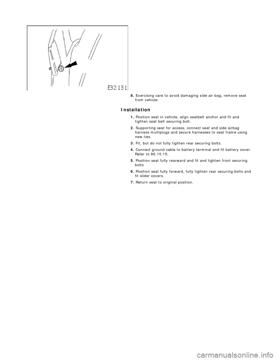
7. NOTE: Securing bolt remains captive with belt anchor.
Slacken and remove seat be lt anchor securing bolt.
Page 2123 of 2490
Installation
8. Exercising care to avoid damagi ng side air bag, remove seat
from vehicle.
1. Position seat in vehicle, align seatbelt anchor and fit and
tighten seat belt securing bolt.
2. Supporting seat for access, co nnect seat and side airbag
harness multiplugs and secure harnesses to seat frame using
new ties.
3. Fit, but do not fully tigh ten rear securing bolts.
4. Connect ground cable to battery terminal and fit battery cover.
Refer to 86.15.15.
5. Position seat fully rearward an d fit and tighten front securing
bolts
6. Position seat fully forward, full y tighten rear securing bolts and
fit slider covers.
7. Return seat to original position.
Page 2124 of 2490
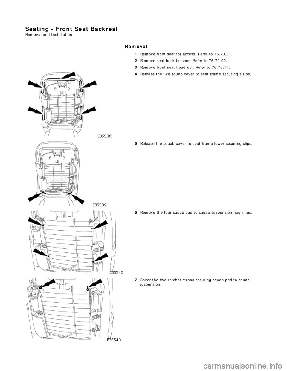
Seating - Front Seat Backrest
Removal and Installation
Removal
1. Remove front seat for ac cess. Refer to 76.70.01.
2. Remove seat back fini sher. Refer to 76.70.09.
3. Remove front seat headrest. Refer to 76.70.14.
4. Release the five squab cover to seat frame securing strips.
5. Release the squab cover to seat frame lower securing clips.
6. Remove the four squab pad to squab suspension hog rings.
7. Sever the two ratchet straps securing squab pad to squab
suspension.
Page 2125 of 2490
Installation
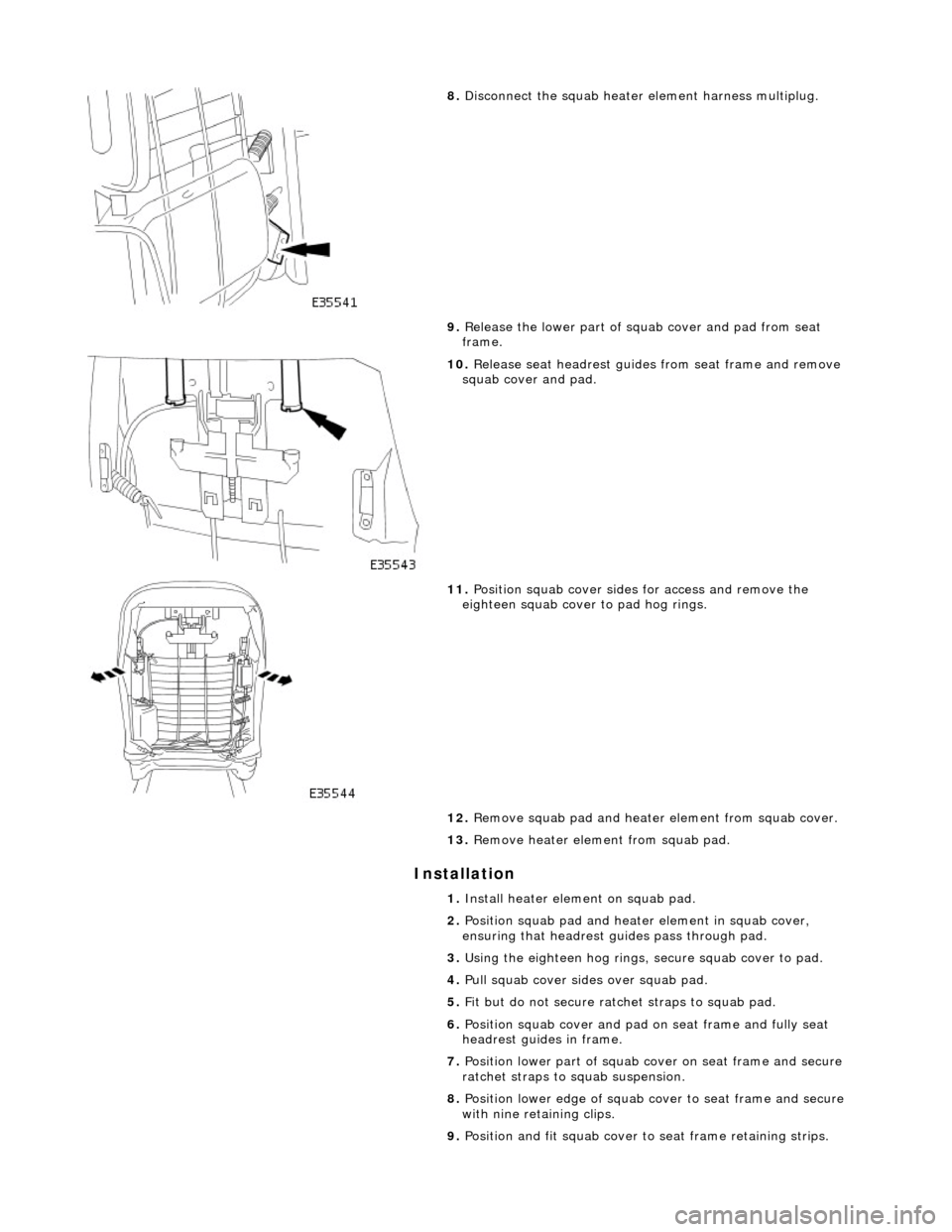
8. Disconnect the squab heater element harness multiplug.
9. Release the lower part of squab cover and pad from seat
frame.
10. Release seat headrest guides from seat frame and remove
squab cover and pad.
11. Position squab cover sides for access and remove the
eighteen squab cover to pad hog rings.
12. Remove squab pad and heater element from squab cover.
13. Remove heater element from squab pad.
1. Install heater element on squab pad.
2. Position squab pad and heater element in squab cover,
ensuring that headrest gu ides pass through pad.
3. Using the eighteen hog rings, secure squab cover to pad.
4. Pull squab cover sides over squab pad.
5. Fit but do not secure ratc het straps to squab pad.
6. Position squab cover and pad on seat frame and fully seat
headrest guides in frame.
7. Position lower part of squab co ver on seat frame and secure
ratchet straps to squab suspension.
8. Position lower edge of squab co ver to seat frame and secure
with nine retaining clips.
9. Position and fit squab cover to seat frame retaining strips.
Page 2126 of 2490

10.
Fit and tighten squab cover upper securing screws.
11. Fit headrest. Refer to 76.70.14.
12. Fit seat back finisher. Refer to 76.70.09.
13. Install front seat in vehi cle. Refer to 76.70.01.