Suspension JAGUAR X308 1998 2.G Owner's Manual
[x] Cancel search | Manufacturer: JAGUAR, Model Year: 1998, Model line: X308, Model: JAGUAR X308 1998 2.GPages: 2490, PDF Size: 69.81 MB
Page 79 of 2490

1
11 and support on stands. Refer to Section 100-02.
5. Ins
tall Special Tool 204-111 in road spring.
Sl
acken tool adjuster to suit spring length.
Install adaptor
and thrust collar.
Posit
ion stem of tool in center of spring passing dowel
through slot in su spension turret.
6. R
otate stem of Special Tool to
position dowel across slot.
7. W
ARNING: WHEN TURNING TOOL ADJUSTER, ENSURE
THAT TOOL STEM DOES NOT ROTATE AND DISTURB POSITION
OF DOWEL IN SUSPENSION TURRET.
Rotate adjuster of Special Tool to tension spring.
8. R
emove spring pan to lower
wishbone securing bolts.
9. Rotate adjuster of Special Tool to release tension from spring.
Page 80 of 2490
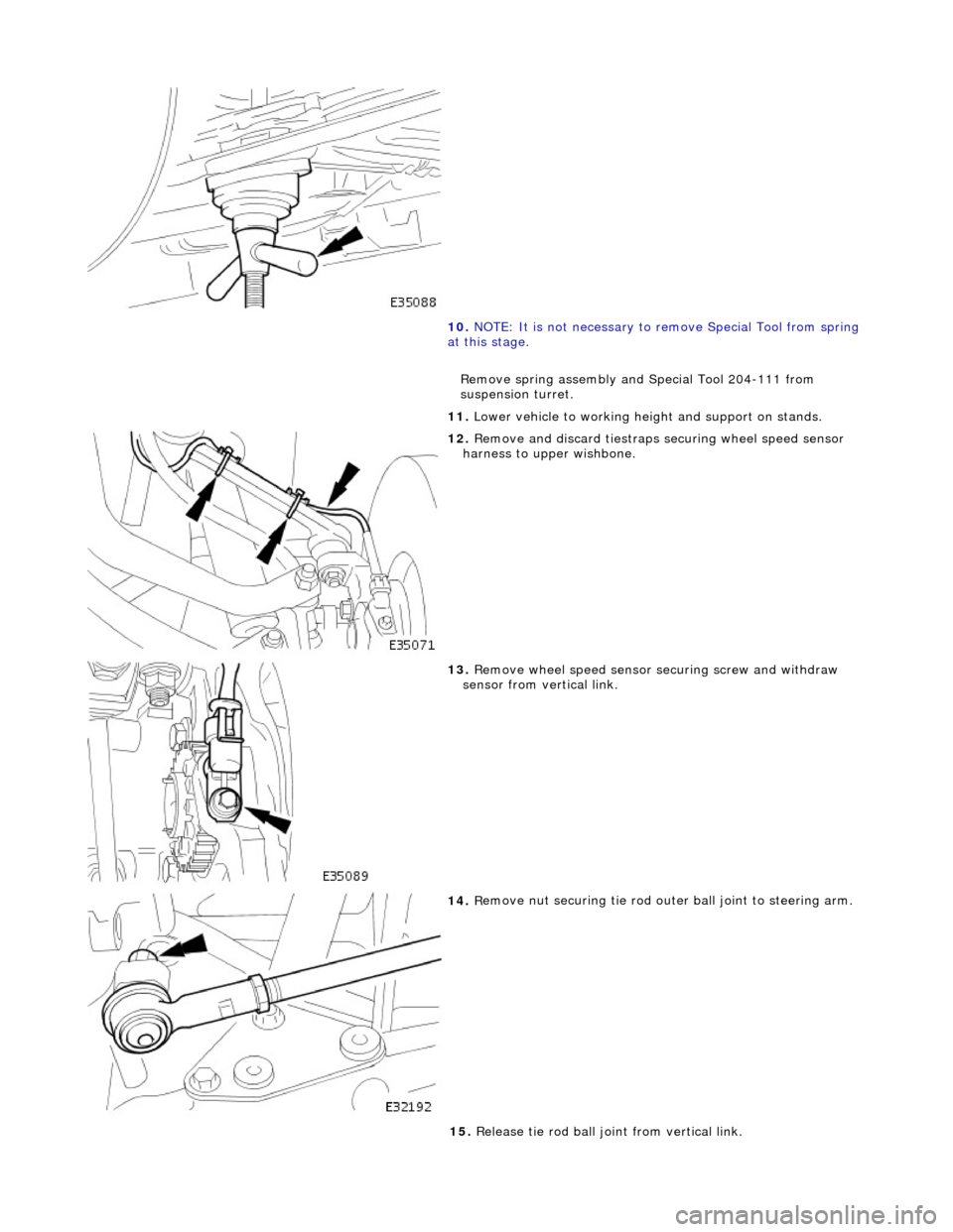
10. NOTE
: It is not necessary to re
move Special Tool from spring
at this stage.
Remove spring assembly and Special Tool 204-111 from
suspension turret.
11. Lower vehicle to working heig ht and support on stands.
12 . Remove an
d discard tiestraps
securing wheel speed sensor
harness to upper wishbone.
13 . R
emove wheel speed sensor se
curing screw and withdraw
sensor from vertical link.
14 . R
emove nut securing tie rod oute
r ball joint to steering arm.
15. Release tie rod ball joint from vertical link.
Page 87 of 2490
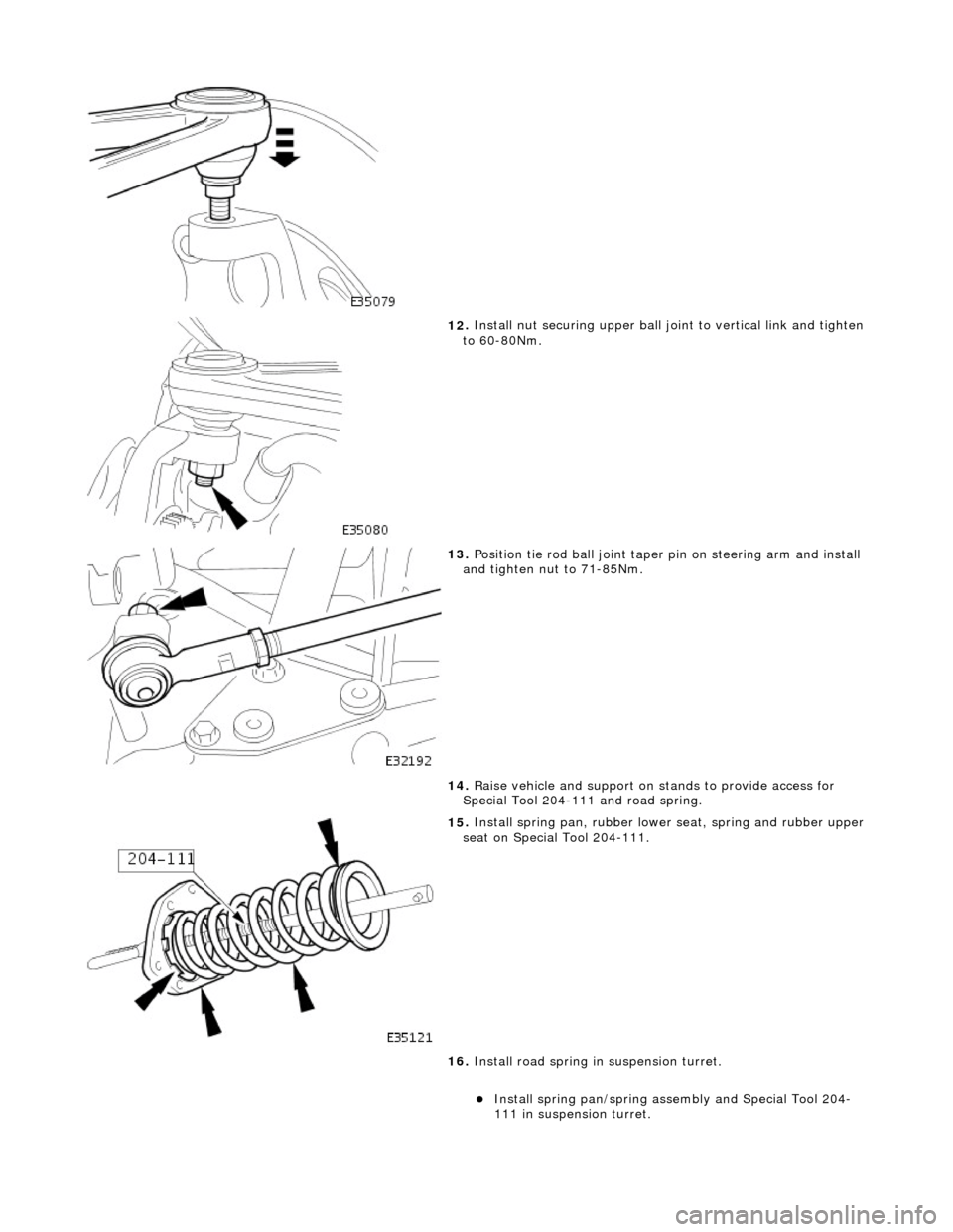
12
.
Install nut securing upper ball jo int to vertical link and tighten
to 60-80Nm.
13
.
Position tie rod ball joint taper pin on steering arm and install
and tighten nut to 71-85Nm.
14. Raise vehicle and support on st ands to provide access for
Special Tool 204-111 and road spring.
15
.
Install spring pan, rubber lowe r seat, spring and rubber upper
seat on Special Tool 204-111.
16. Install road spring in suspension turret.
Install
spring pan/spring as
sembly and Special Tool 204-
111 in suspension turret.
Page 88 of 2490
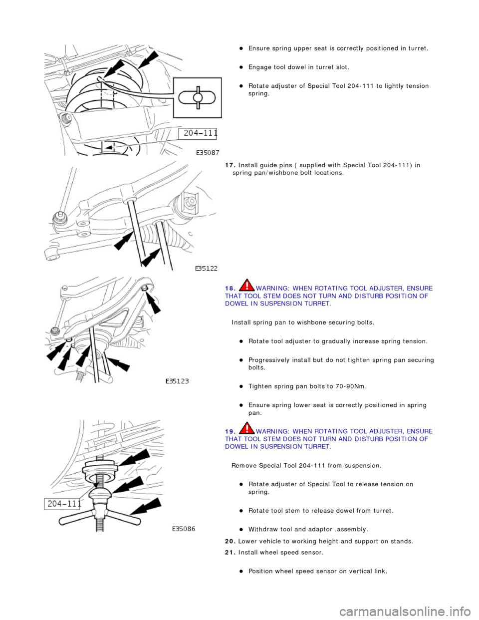
Ensure spring
upper se
at is correctly positioned in turret.
Engage tool dowel in turret slo
t.
R
o
tate adjuster of Special Tool 204-111 to lightly tension
spring.
17 . Ins
tall guide pins ( supplied with Special Tool 204-111) in
spring pan/wishbone bolt locations.
18 . WARNING: WHE
N ROTATING TOOL ADJUSTER, ENSURE
THAT TOOL STEM DOES NOT TU RN AND DISTURB POSITION OF
DOWEL IN SUSPENSION TURRET.
Install spring pan to wishbone securing bolts.
Ro t
ate tool adjuster to gradua
lly increase spring tension.
Pr
ogressively install but do no
t tighten spring pan securing
bolts.
Tigh ten spring pan
bolts to 70-90Nm.
Ensure spri
ng
lower seat is co
rrectly positioned in spring
pan.
19 . WARNING: WHE
N ROTATING TOOL ADJUSTER, ENSURE
THAT TOOL STEM DOES NOT TU RN AND DISTURB POSITION OF
DOWEL IN SUSPENSION TURRET.
Remove Special Tool 204-111 from suspension.
Rotat
e adjuster of Special Tool to release tension on
spring.
R otate
tool stem to release dowel from turret.
With
draw tool and adaptor
.assembly.
20
. Lower vehi
cle to working heig
ht and support on stands.
21. Install wheel speed sensor.
Positi
on wheel speed sensor on vertical link.
Page 90 of 2490

Front Suspension - Rear Lower Arm Bushing
Remo
val and Installation
Remov
a
l
CAUTI
O
N: Replacement of
nuts and bolts: Various thread-locking devices are used on nuts and bolts throughout the
vehicle. These devices restrict the number of times a nut or bolt can be used. Refer to Section 100-00 for further
information.
S p
ecial Tool(s)
R
o
ad spring compressor
204-111 (JD115)
Taper separator
2
11-098 (JD 100)
Ball
Jo
int Taper Separator
204-192 (JD 219)
Bal l
joint splitter
204-293
1. Ra
ise front of vehicle and support on stands. Refer to Section
100-02.
2. Remove appropriate road wheel. Refer to Section 100-02.
3. CAUTIO
N: Do not suspend caliper from brake hose as
this will damage the hose.
Remove brake calipers from carriers. 1. Remove caliper spring clip.
2. Remove guide pin dust caps.
3. Slacken and withdraw guide pins.
4. Remove caliper from carrier and tie to suspension mounting bracket.
4. Ra
ise vehicle further to provid
e access for Special Tool 204-
Page 91 of 2490

1
11 and support on stands. Refer to Section 100-02.
5. Ins
tall Special Tool 204-111 in road spring.
Sl
acken tool adjuster to suit spring length.
Fit adaptor and th
rust collar.
Posit
ion stem of tool in center of spring passing dowel
through slot in su spension turret.
6. R
otate stem of Special Tool to
position dowel across slot.
7. W
ARNING: WHEN TURNING TOOL ADJUSTER, ENSURE
THAT TOOL STEM DOES NOT ROTATE AND DISTURB POSITION
OF DOWEL IN SUSPENSION TURRET.
Rotate adjuster of Special Tool to tension spring.
8. R
emove spring pan securing bolts.
9. Rotate adjuster of Special Tool to release tension from spring.
Page 92 of 2490

10. NOTE
: It is not necessary to re
move Special Tool from spring
at this stage.
Remove spring assembly and Special Tool 204-111 from
suspension turret.
11. Lower vehicle to working heig ht and support on stands.
12 . Re
move tiestraps securing wheel speed sensor harness to
upper wishbone.
13 . R
emove wheel speed sensor se
curing screw and withdraw
sensor from vertical link.
14. Remove nut securing tie rod oute r ball joint to steering arm.
Page 101 of 2490
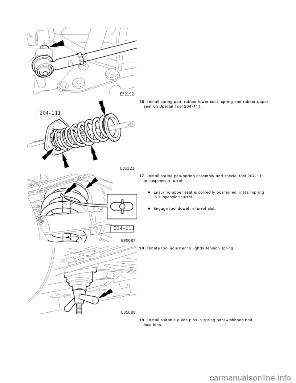
16
.
Install spring pan, rubber lowe r seat, spring and rubber upper
seat on Special Tool 204-111.
17
.
Install spring pan/spring asse mbly and special tool 204-111
in suspension turret.
E
nsuring upper seat is correctly positioned, install spring
in suspension turret.
Engage tool
dowel in turret slot.
18
.
Rotate tool adjuster to lightly tension spring.
19. Install suitable guide pins in spring pan/wishbone bolt
locations.
Page 102 of 2490
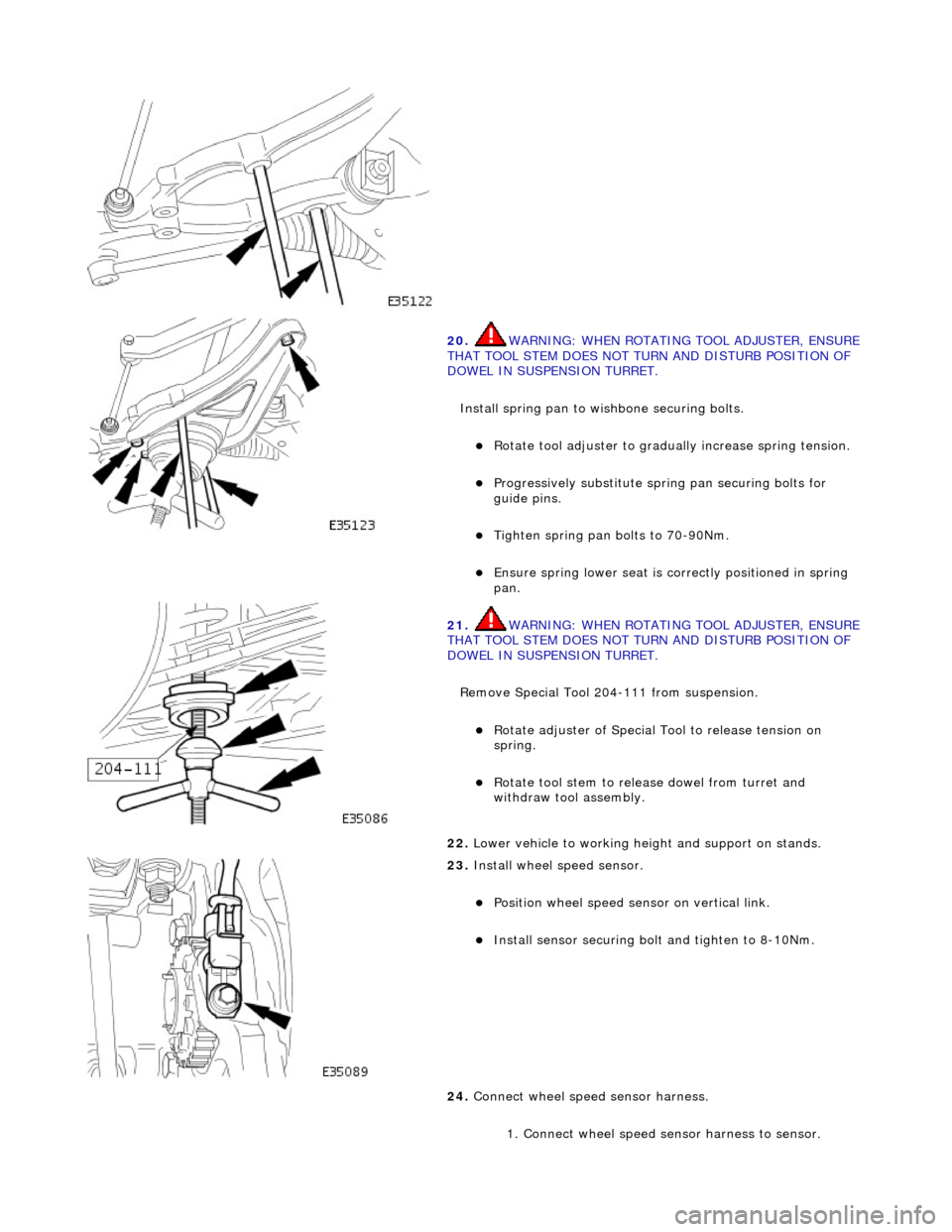
20. WARNING: WHE
N ROTATING TOOL ADJUSTER, ENSURE
THAT TOOL STEM DOES NOT TU RN AND DISTURB POSITION OF
DOWEL IN SUSPENSION TURRET.
Install spring pan to wishbone securing bolts.
Ro t
ate tool adjuster to gradua
lly increase spring tension.
Pr
ogressively substitute spri
ng pan securing bolts for
guide pins.
Tighten spring pan
bolts to 70-90Nm.
Ensure spri
ng
lower seat is co
rrectly positioned in spring
pan.
21 . WARNING: WHE
N ROTATING TOOL ADJUSTER, ENSURE
THAT TOOL STEM DOES NOT TU RN AND DISTURB POSITION OF
DOWEL IN SUSPENSION TURRET.
Remove Special Tool 204-111 from suspension.
Rotat
e adjuster of Special Tool to release tension on
spring.
R o
tate tool stem to release dowel from turret and
withdraw tool assembly.
22 . Lower vehi
cle to working heig
ht and support on stands.
23 . Inst
all wheel speed sensor.
Posi
ti
on wheel speed sensor on vertical link.
Instal
l sensor securing bolt
and tighten to 8-10Nm.
24. Connect wheel speed sensor harness.
1. Connect wheel speed sensor harness to sensor.
Page 105 of 2490
Front Suspension - Fron
t Shock Absorber
Re
moval and Installation
Remov
al
S
pecial Tool(s)
Front Camber Tie-do
wn Link
204-114 (JD 133)
1. CAUTION: Replacement of nuts and bolts: Various
thread-locking devices are used on nuts and bolts throughout the
vehicle. These devices restrict the number of times a nut or bolt
can be used.
For additional informat ion, refer to Section 100
-0
0 General
Informati
on
.
R
aise the front of the vehicle.
For additional informat ion, refer to Section 100
-0
2 Jacking and
Liftin
g
.
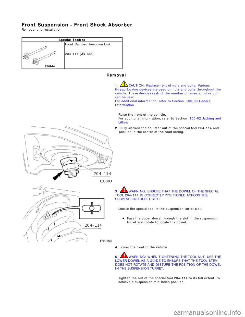
2.
Ful
ly slacken the adjuster nut of the special tool 204-114 and
position in the center of the road spring.
3. W
ARNING: ENSURE THAT THE DOWEL OF THE SPECIAL
TOOL 204-114 IS CORRECTLY POSITIONED ACROSS THE
SUSPENSION TURRET SLOT.
Locate the special tool in the suspension turret slot.
Pass
the upper dowel through the slot in the suspension
turret and rotate to locate the dowel.
4. Lower the front o
f
the vehicle.
5. WARNING: WHEN TIGHTENING THE TOOL NUT, USE THE
LOWER DOWEL AS A GUIDE TO ENSURE THAT THE TOOL STEM
DOES NOT ROTATE AND DISTURB THE POSITION OF THE DOWEL
IN THE SUSPENSION TURRET.
Tighten the nut of the special tool 204-114 to its full extent, to
achieve a suspension mid-laden position.