Suspension JAGUAR X308 1998 2.G Repair Manual
[x] Cancel search | Manufacturer: JAGUAR, Model Year: 1998, Model line: X308, Model: JAGUAR X308 1998 2.GPages: 2490, PDF Size: 69.81 MB
Page 176 of 2490

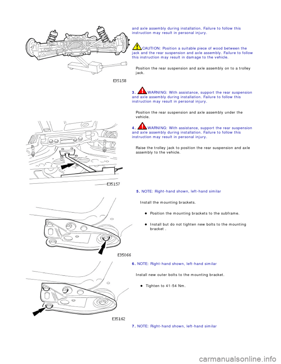
and axle assembly during installa
tion. Failure to follow this
instruction may result in personal injury.
CAUTION: Position a suitable piece of wood between the
jack and the rear suspension and axle assembly. Failure to follow
this instruction may result in damage to the vehicle.
Position the rear suspension and axle assembly on to a trolley
jack.
3. WARN
ING: With assistance, support the rear suspension
and axle assembly during instal lation. Failure to follow this
instruction may result in personal injury.
Position the rear suspension and axle assembly under the
vehicle.
4. WARN
ING: With assistance, support the rear suspension
and axle assembly during instal lation. Failure to follow this
instruction may result in personal injury.
Raise the trolley jack to position the rear suspension and axle
assembly to the vehicle.
5. NOTE : R
ight-hand shown, left-hand similar
Install the mounting brackets.
Po si
tion the mounting brackets to the subframe.
Install but do not tigh
ten
new bolts to the mounting
bracket .
6. NOTE: R
ight-hand shown, left-hand similar
Install new outer bolts to the mounting bracket.
Tigh te
n to 41-54 Nm.
7. NOTE: Right-hand shown, left-hand similar
Page 179 of 2490

18
.
Install the brake caliper on to the carrier.
1. Position the caliper asse mbly on to the carrier.
2. Install the guide pins and tighten to 25-30 Nm.
3. Install the dust caps.
4. Install the brake caliper spring clip.
19
.
Connect the wheel speed sensor electrical connector.
20
.
Using a new tie strap, secure the wheel speed sensor harness
to the brake hose clip.
21. Install the rear wheels.
For additional informat ion, refer to Section 204
-04
Wheels and
Tire
s
.
22
.
Remove the axle stands and lower the vehicle.
For additional informat ion, refer to Section 100
-0
2 Jacking and
Liftin
g
.
23
.
Check and adjust the rear whee l alignment as necessary.
For additional informat ion, refer to Section 204
-00
Suspension
Sy
stem
- General
Information
.
Page 180 of 2490

Rear Su
spension - Rear Shock Absorber
Re
mo
val and Installation
Remov
a
l
S
p
ecial Tool(s)
Spri
ng C
ompressors
204-179 (JD 199)
Spri ng Re
taining straps
204-179-1 (JD 199-1)
1. CAUTION: Replacement of nuts and bolts: Various
thread-locking devices are used on nuts and bolts throughout the
vehicle. These devices restrict the number of times a nut or bolt
can be used.
For additional informat ion, refer to Section 100
-00
General
Informati
o
n
.
R a
ise the rear of the vehicle
and support on axle stands.
For additional informat ion, refer to Section 100
-02
Jacking and
Liftin
g.
2. Re
move the relevant rear wheel.
For additional informat ion, refer to Section 204
-04 W
heels and
Tire
s.
3. CAUTIO
N: Do not suspend the caliper from the brake
hose as this will damage the hose.
Remove the brake caliper from the carrier.
1. Remove the caliper spring clip.
2. Remove the guide pin dust caps.
3. Slacken and withdr aw the guide pins.
4. Remove the caliper from the carrier and secure to the suspension mounting bracket using a tie strap.
4. Disc
onnect the wheel speed sensor electrical connector.
Page 190 of 2490

22. R
elease the tie strap securing the brake caliper to the
suspension mounting bracket.
23 . Install
the brake caliper on to the carrier.
1. Position the caliper asse mbly on to the carrier.
2. Install the guide pins and tighten to 25-30 Nm.
3. Install the dust caps.
4. Install the brake caliper spring clip.
24 . Conne
ct the wheel speed sensor electrical connector.
25 . U
sing a new tie strap, secure the wheel speed sensor harness
to the brake hose clip.
26. Install the rear wheel.
For additional informat ion, refer to Section 204
-04 W
heels and
Tire
s.
27 .
Remove the
axle stands
and lower the vehicle.
For additional informat ion, refer to Section 100
-02
Jacking and
Liftin
g.
Page 191 of 2490

28
.
Check and adjust the rear whee l alignment as necessary.
For additional informat ion, refer to Section 204
-00
Suspension
Sy
stem
- General
Information
.
Page 192 of 2490

Rear Su
spension - Shock Absorber Lower Bushing
Re
mo
val and Installation
Remov
a
l
S
p
ecial Tool(s)
B
u
shing Remover / installer
204-335
Bushing remover
2 04-
533
B
u
shing installer
204-534
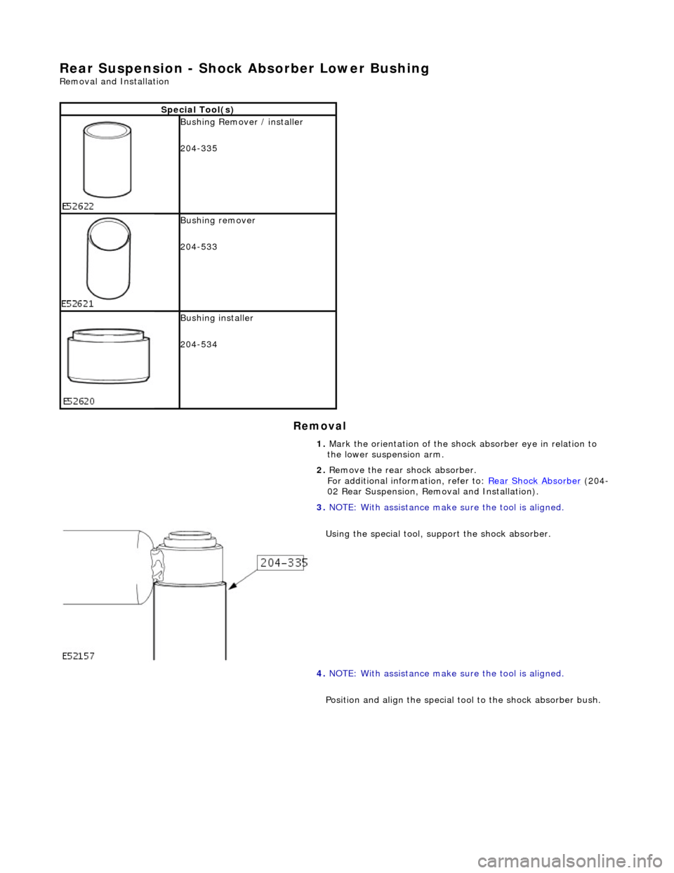
1. Mark the orientation of the shock absorber eye in relation to
the lower suspension arm.
2. Remove the rear shock absorber.
For additional information, refer to: Rear Shock Absorber
(20 4
-
02 Rear Suspension, Removal and Installation).
3. NOTE : W
ith assistance make sure the tool is aligned.
Using the special tool, support the shock absorber.
4. NOTE: With assistance make sure the tool is aligned.
Position and align the special tool to the shock absorber bush.
Page 194 of 2490

reach
es the stop.
4. Install the rear shock absorber.
For additional information, refer to: Rear Shock Absorber
(204
-
02 Rear Suspension, Removal and Installation).
Page 195 of 2490

Rear
Suspension - Spring
Re
moval and Installation
Remov
al
S
pecial Tool(s)
Spri
ng Compressors
204-179 (JD 199)
Spri
ng Retaining straps
204-179-1 (JD 199-1)
1. CAUTION: Replacement of nuts and bolts: Various
thread-locking devices are used on nuts and bolts throughout the
vehicle. These devices restrict the number of times a nut or bolt
can be used.
For additional informat ion, refer to Section 100
-0
0 General
Informati
on
.
R
aise the rear of the vehicle
and support on axle stands.
For additional informat ion, refer to Section 100
-0
2 Jacking and
Liftin
g
.
2.
R
emove the relevant rear wheel.
For additional informat ion, refer to Section 204
-04
Wheels and
Tire
s
.
3. CAUTI
ON: Do not suspend the caliper from the brake
hose as this will damage the hose.
Remove the brake caliper from the carrier.
1. Remove the caliper spring clip.
2. Remove the guide pin dust caps.
3. Slacken and withdr aw the guide pins.
4. Remove the caliper from the carrier and secure to the suspension mounting bracket using a tie strap.
4. Di
sconnect the wheel speed sensor electrical connector.
Page 206 of 2490

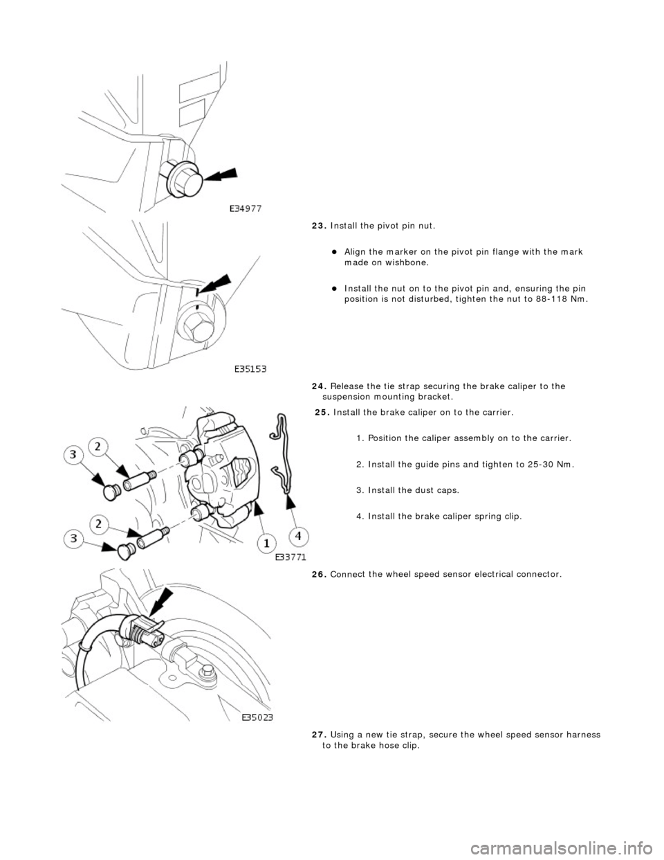
23. Inst
all the pivot pin nut.
Ali
g
n the marker on the pivo
t pin flange with the mark
made on wishbone.
Inst al
l the nut on to the pivot pin and, ensuring the pin
position is not dist urbed, tighten the nut to 88-118 Nm.
24. Release the tie strap securing the brake caliper to the
suspension mounting bracket.
25 . Install
the brake caliper on to the carrier.
1. Position the caliper asse mbly on to the carrier.
2. Install the guide pins and tighten to 25-30 Nm.
3. Install the dust caps.
4. Install the brake caliper spring clip.
26 . Conne
ct the wheel speed sensor electrical connector.
27. Using a new tie strap, secure the wheel speed sensor harness
to the brake hose clip.
Page 207 of 2490

28
.
Install the rear wheel.
For additional informat ion, refer to Section 204
-04
Wheels and
Tire
s
.
29
.
Remove the axle stands and lower the vehicle.
For additional informat ion, refer to Section 100
-0
2 Jacking and
Liftin
g
.
30
.
Check and adjust the rear whee l alignment as necessary.
For additional informat ion, refer to Section 204
-00
Suspension
Sy
stem
- General
Information
.