Suspension JAGUAR X308 1998 2.G Service Manual
[x] Cancel search | Manufacturer: JAGUAR, Model Year: 1998, Model line: X308, Model: JAGUAR X308 1998 2.GPages: 2490, PDF Size: 69.81 MB
Page 122 of 2490
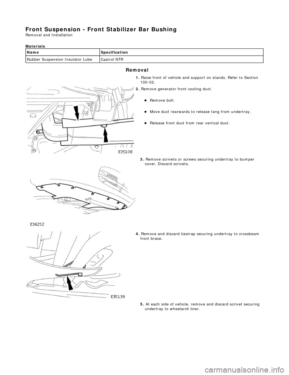
Front Suspension - Front Stabilizer B
ar Bushing
Re
mo
val and Installation
Materials
S p
ecification
Cas
t
rol NTR
Remov
a
l
Na
m
e
R
u
bber Suspension Insulator Lube
1. Raise front of vehicle and support on stands. Refer to Section
100-02.
2. Re
move generator front cooling duct.
Re
mo
ve bolt.
Move duct rea
r
wards to rele
ase tang from undertray.
Re
lease front duct from rear vertical duct.
3. Re
move scrivets or screws se
curing undertray to bumper
cover. Discard scrivets.
4. Re
move and discard tiestrap securing undertray to crossbeam
front brace.
5. At each side of vehicle, remo ve and discard scrivet securing
undertray to wheelarch liner.
Page 127 of 2490
Front Suspension - Front Stabiliz
er Bar Link
Re
moval and Installation
Remov
al
Installation
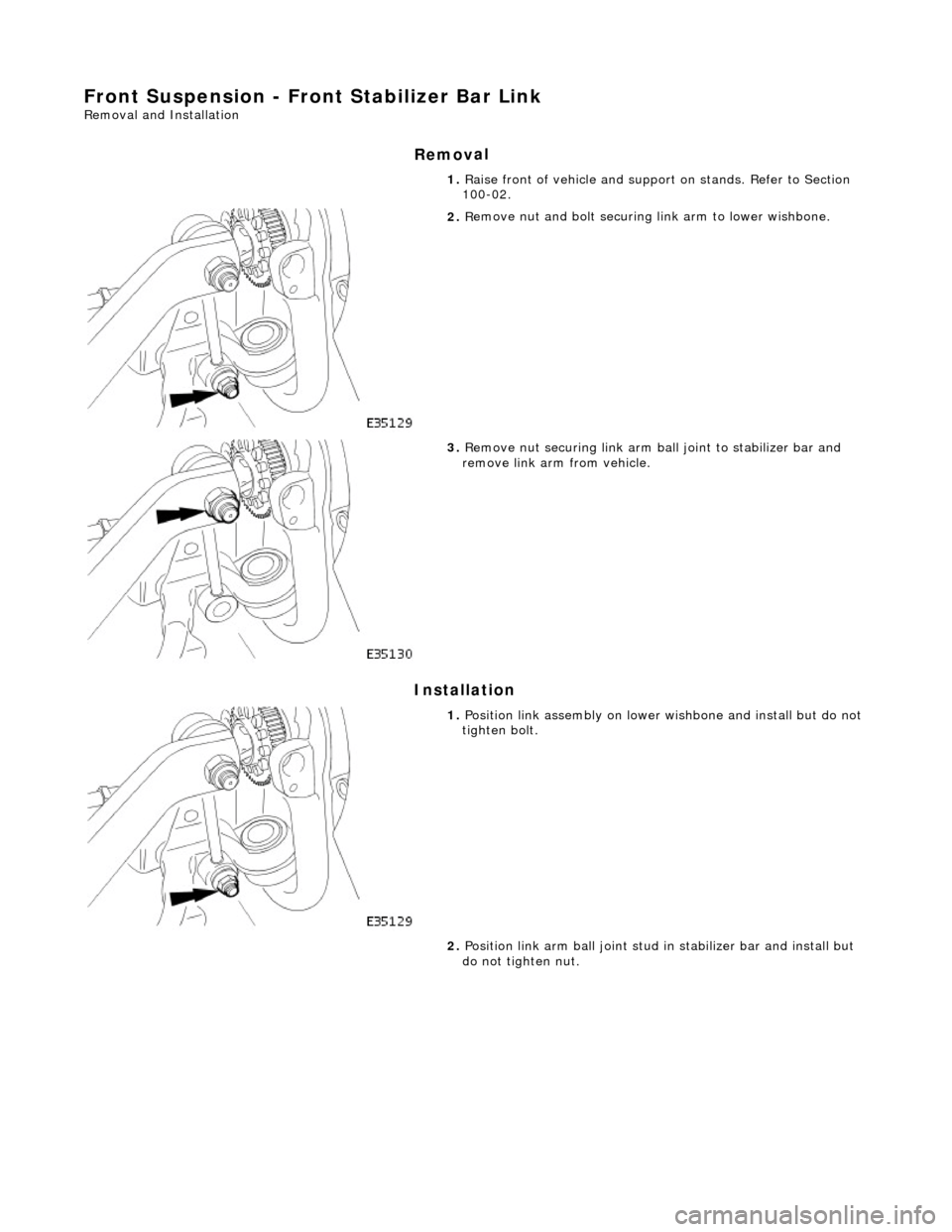
1. R
aise front of vehicle and support on stands. Refer to Section
100-02.
2. R
emove nut and bolt securing
link arm to lower wishbone.
3. R
emove nut securing link arm ba
ll joint to stabilizer bar and
remove link arm from vehicle.
1. Position li
nk assembly on lower
wishbone and install but do not
tighten bolt.
2. Position link arm ball joint stud in stabilizer bar and install but
do not tighten nut.
Page 129 of 2490

Front Suspension - Upper Arm Bushing
Re
moval and Installation
Remov
al
CAUTI
ON: Replacement of
nuts and bolts: Various thread-locking devices are used on nuts and bolts throughout the
vehicle. These devices restrict the number of times a nut or bolt can be used. See section 100-00 for information.
S
pecial Tool(s)
Ball
Joint Taper Separator
204-192 (JD 219)
Front Camber Tie-do
wn Link
204-114 (JD 133)
1. R
aise front of vehicle.
Refer to Section 100-02.
2. P
osition camber tie down spec
ial tool 204-114 on suspension.
Fully s
lacken tool adjuster nut.
Position too
l in road spring and pass upper dowel through
slot in suspen sion turret.
3. Lower front of vehicle.
4. R
otate stem of special tool 204-114 to locate dowel in
suspension turret slot.
5. WARNING: WHEN TIGHTENING TOOL NUT, USE LOWER
DOWEL AS A GUIDE TO ENSURE THAT THE TOOL STEM DOES
NOT ROTATE AND DISTURB POSITION OF DOWEL IN
SUSPENSION TURRET.
Fully tighten nut of special tool to achieve suspension mid-laden
Page 130 of 2490
positio
n.
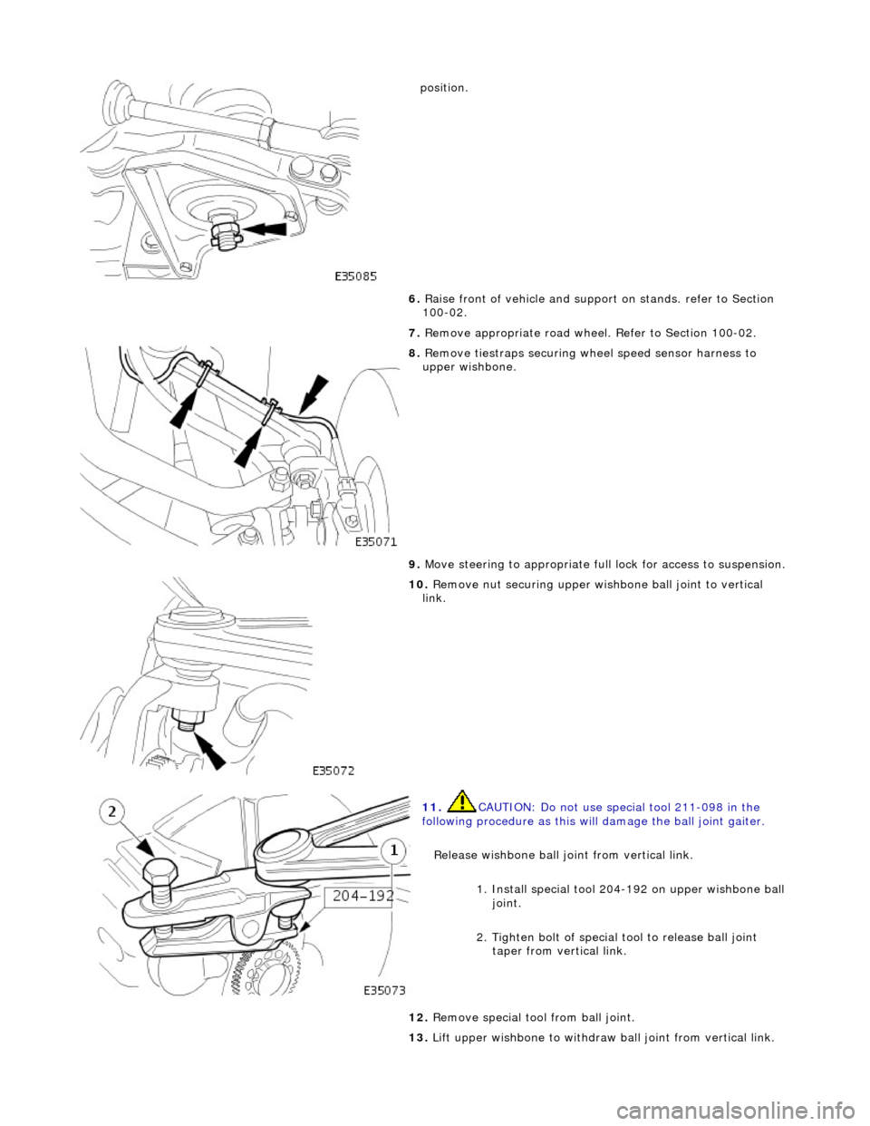
6. Raise front of vehicle and support on stands. refer to Section
100-02.
7. Remove appropriate road wheel. Refer to Section 100-02.
8. Remove t
iestraps securing wheel speed sensor harness to
upper wishbone.
9. Move steering to appropriate full lock for access to suspension.
10. R
emove nut securing upper wish
bone ball joint to vertical
link.
11 . CAUTI
ON: Do not use special tool 211-098 in the
following procedure as this will damage the ball joint gaiter.
Release wishbone ball joint from vertical link.
1. Install special tool 204-192 on upper wishbone ball joint.
2. Tighten bolt of special tool to release ball joint
taper from vertical link.
12 . Re
move special tool from ball joint.
13. Lift upper wishbone to withdraw ball joint from vertical link.
Page 134 of 2490

17.
R
elease dowel of special tool 204-114 from suspension turret
slot.
18. Raise vehicle for access an d remove special tool from
suspension.
19. Fully lower vehicle.
20. Carry out steering geometry an d wheel alignment checks and
if necessary adjust. Refer to 57.65.01.
Page 135 of 2490

Front Suspension - Front Wheel Bearing
Re
moval and Installation
S
pecial Tool(s)
Hub Remover
204-193 (JD 224)
Hub Removal Collets
2
04-194 (JD 225)
Hub Holdin
g Tool
204-195 (JD 227)
Hub Replacer
2
04-196 (JD 236)
Wh
eel Bearing Remover
204-197 (JD 237)
Wh
eel Bearing Replacer
204-198 (JD 238)
ABS Rotor Nut Socket
20
6-066A
Ci
rclip Pliers
Page 147 of 2490

Front Suspension - Wheel Knuckle
Re
moval and Installation
S
pecial Tool(s)
Hub Remover
204-193 (JD 224)
Hub Removal Collets
2
04-194 (JD 225)
Hub Holdin
g Tool
204-195 (JD 227)
Hub Replacer
2
04-196 (JD 236)
Wh
eel Bearing Remover
204-197 (JD 237)
Wh
eel Bearing Replacer
204-198 (JD 238)
ABS Rotor Nut Socket
20
6-066A
Ci
rclip Pliers
Page 153 of 2490
Front Susp
ension - Wheel Knuckle and Wheel Hub Assembly
Re
moval and Installation
Remov
al
S
pecial Tool(s)
R
oad spring compressor
204-111 (JD115)
Taper separator
211-098 (JD 100)
Front
suspension ball joint splitter
204-192 (JD 219)
Bal
l joint splitter
204-293
1. Raise front of vehicle and support on stands. Refer to Section
100-02.
2. Remove appropriate road wheel. Refer to 74.20.05.
3. Remove brake disc. Refer to 70.10.12.
4. Using wire or string, secure brak e caliper to road spring to take
weight off brake hose.
5. Raise vehicle sufficient to provide access for special tool 204-
111.
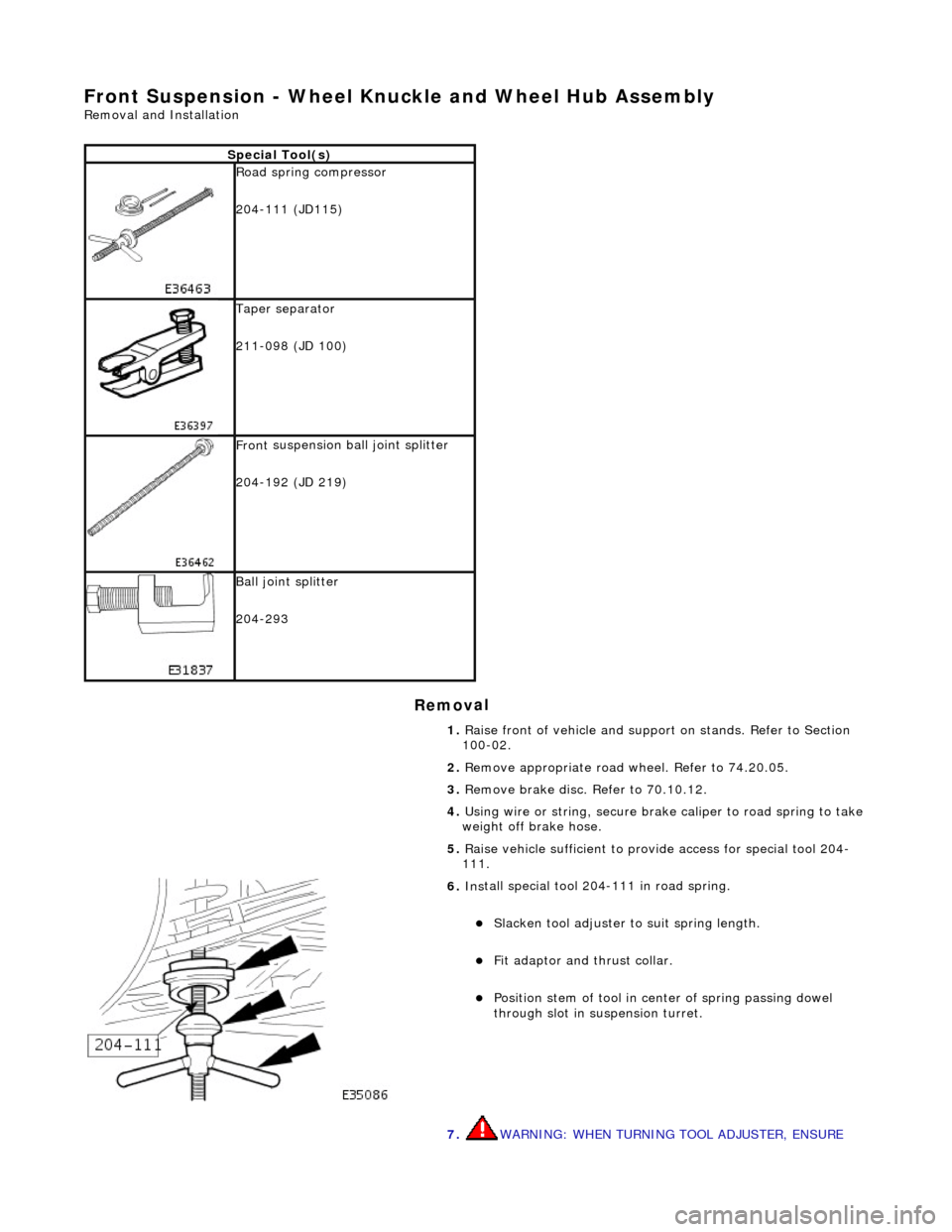
6. Ins
tall special tool 204-111 in road spring.
Sl
acken tool adjuster to suit spring length.
Fit adaptor and th
rust collar.
Posit
ion stem of tool in center of spring passing dowel
through slot in su spension turret.
7. WARNING: WHEN TURNING TOOL ADJUSTER, ENSURE
Page 154 of 2490

THAT TOOL STEM
DOES NOT ROTATE AND DISTURB POSITION
OF DOWEL IN SUSPENSION TURRET.
Engage dowel of special tool 204-111 in suspension turret and
rotate to position across slot.
8. Lower vehicle onto stands.
9. Ro
tate tool adjuster to tension spring.
10 . R
emove wheel speed sensor se
curing screw and withdraw
sensor from vertical link.
11 . R
emove nut securing tie rod oute
r ball joint to steering arm.
12. Release ball joint from vertical link.
1. Install special tool 211-098 on tie rod outer ball joint.
2. Tighten tool bolt to rele ase taper pin from vertical
link.
Page 156 of 2490
In
stallation
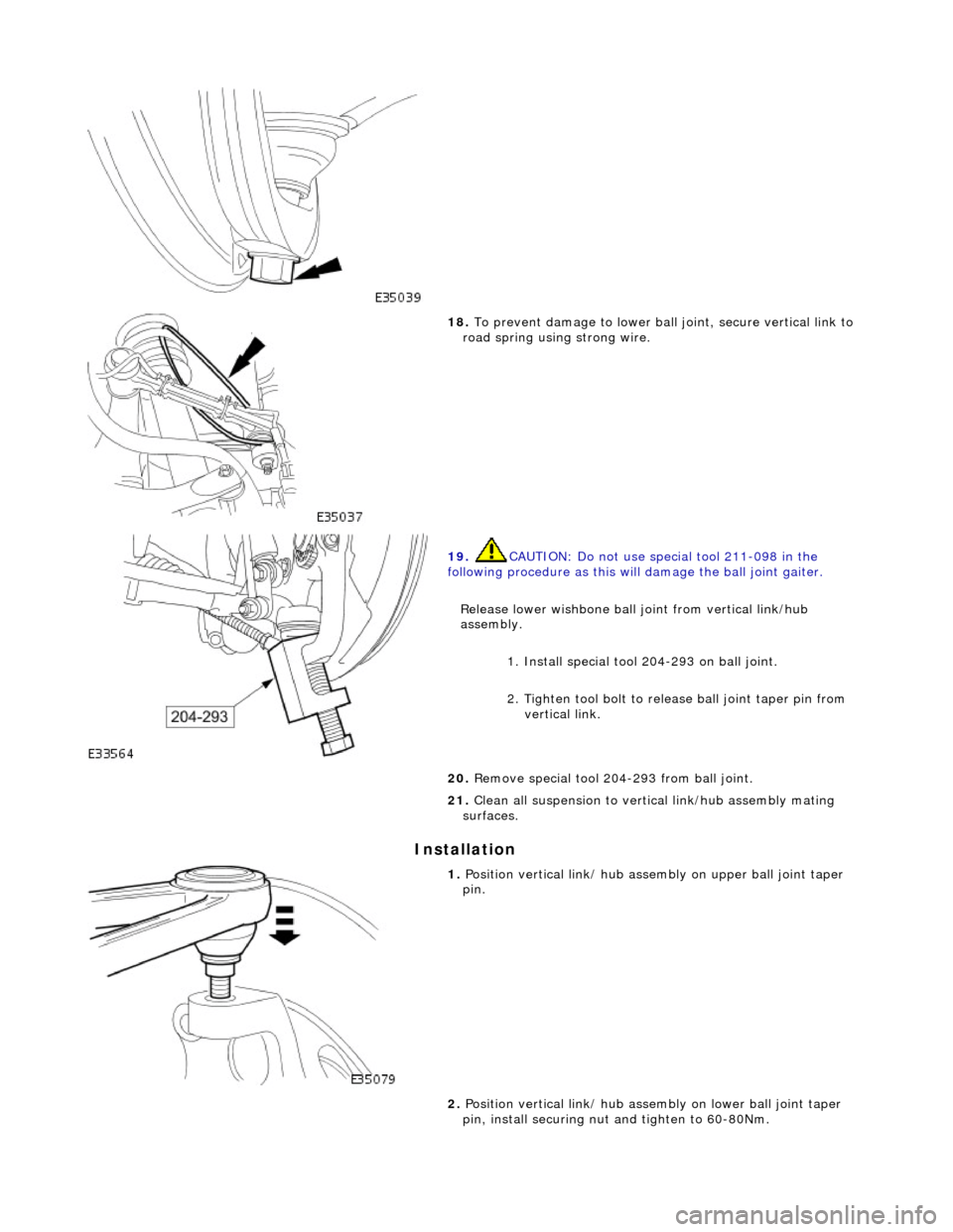
18
. To
prevent damage to lower ball
joint, secure vertical link to
road spring using strong wire.
19 . CAUTI
ON: Do not use special tool 211-098 in the
following procedure as this will damage the ball joint gaiter.
Release lower wishbone ball joint from vertical link/hub
assembly. 1. Install special tool 204-293 on ball joint.
2. Tighten tool bolt to rele ase ball joint taper pin from
vertical link.
20 .
R
emove special tool 204-293 from ball joint.
21. Clean all suspension to vertical link/hub assembly mating
surfaces.
1. Position verti c
al link/ hub asse
mbly on upper ball joint taper
pin.
2. Position vertical link/ hub asse mbly on lower ball joint taper
pin, install securing nut and tighten to 60-80Nm.