JAGUAR X308 1998 2.G Owner's Manual
X308 1998 2.G
JAGUAR
JAGUAR
https://www.carmanualsonline.info/img/21/7640/w960_7640-0.png
JAGUAR X308 1998 2.G Owner's Manual
Page 2388 of 2490
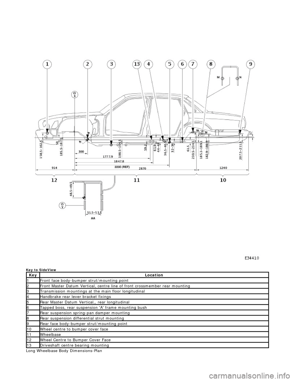
Key to SideView
Long Wheelbase Body Dimensions-Plan
KeyLocation
1Front face body-bumper strut/mounting point
2Front Master Datum Vertical, centre line of front crossmember rear mounting
3Transmission mountings at the main floor longitudinal
4Handbrake rear lever bracket fixings
5Rear Master Datum Vertical,, rear longitudinal
6Tapped boss, rear suspensi on 'A' frame mounting bush
7Rear suspension spring-pan damper mounting
8Rear suspension differential strut mounting
9Rear face body-bumper strut/mounting point
10Wheel centre to bumper cover face
11Wheelbase
12Wheel Centre to Bumper Cover Face
13Driveshaft centre bearing mounting
Page 2389 of 2490
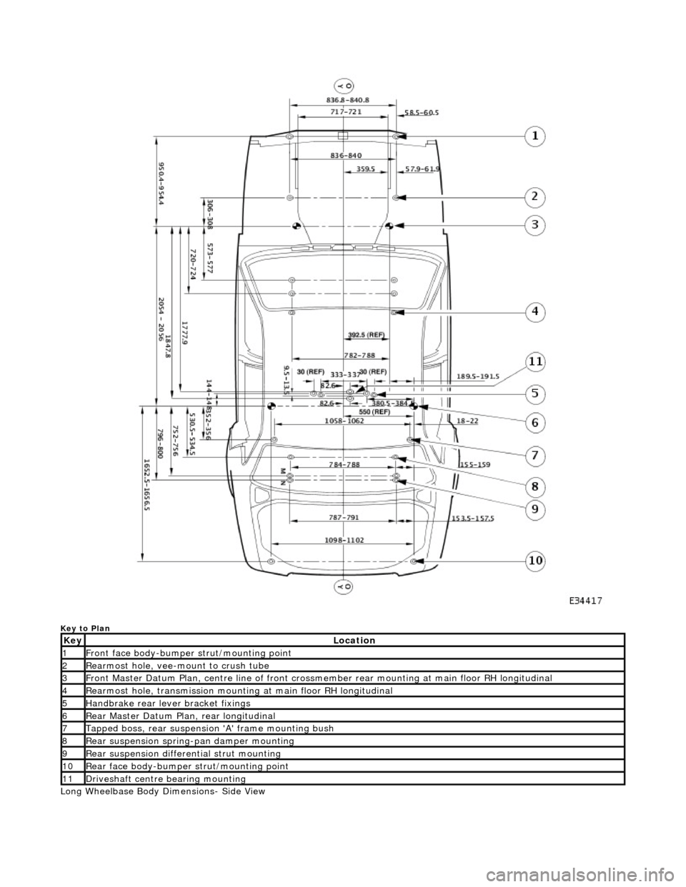
Key to Plan
Long Wheelbase Body Dimensions- Side View
KeyLocation
1Front face body-bumper strut/mounting point
2Rearmost hole, vee-mount to crush tube
3Front Master Datum Plan, centre line of front crossmember rear mount ing at main floor RH longitudinal
4Rearmost hole, transmission mounting at main floor RH longitudinal
5Handbrake rear lever bracket fixings
6Rear Master Datum Plan, rear longitudinal
7Tapped boss, rear suspension 'A' frame mounting bush
8Rear suspension spring-pan damper mounting
9Rear suspension differential strut mounting
10Rear face body-bumper strut/mounting point
11Driveshaft centre bearing mounting
Page 2390 of 2490
Key to SideView
KeyLocation
1Front face body-bumper strut/mounting point
2Front Master Datum Vertical, centre line of front crossmember rear mounting
3Transmission mountings at the main floor longitudinal
4Handbrake rear lever bracket fixings
5Rear Master Datum Vertical,, rear longitudinal
6Tapped boss, rear suspensi on 'A' frame mounting bush
7Rear suspension spring-pan damper mounting
8Rear suspension differential strut mounting
9Rear face body-bumper strut/mounting point
10Wheel centre to bumper cover face
11Wheelbase
12Wheel Centre to Bumper Cover Face
13Driveshaft centre bearing mounting
Page 2481 of 2490
Uni-Body, Subframe and Mounting System - Rear Axle Crossmember
Removal and Installation
Removal
CAUTION: Replacement of nuts and bolts: Various thread-locking devices are used on nuts and bolts throughout the
vehicle. These devices restrict the number of times a nut or bolt can be used. See section 100-00 for information.
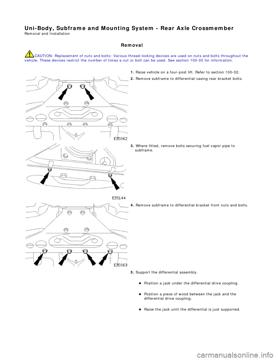
1. Raise vehicle on a four-post li ft. Refer to section 100-02.
2. Remove subframe to differentia l-casing rear bracket bolts.
3. Where fitted, remove bolts se curing fuel vapor pipe to
subframe.
4. Remove subframe to differential bracket front nuts and bolts.
5. Support the differential assembly.
Position a jack under the differential drive coupling.
Position a piece of wood between the jack and the
differential drive coupling.
Raise the jack until the diffe rential is just supported.
Page 2482 of 2490
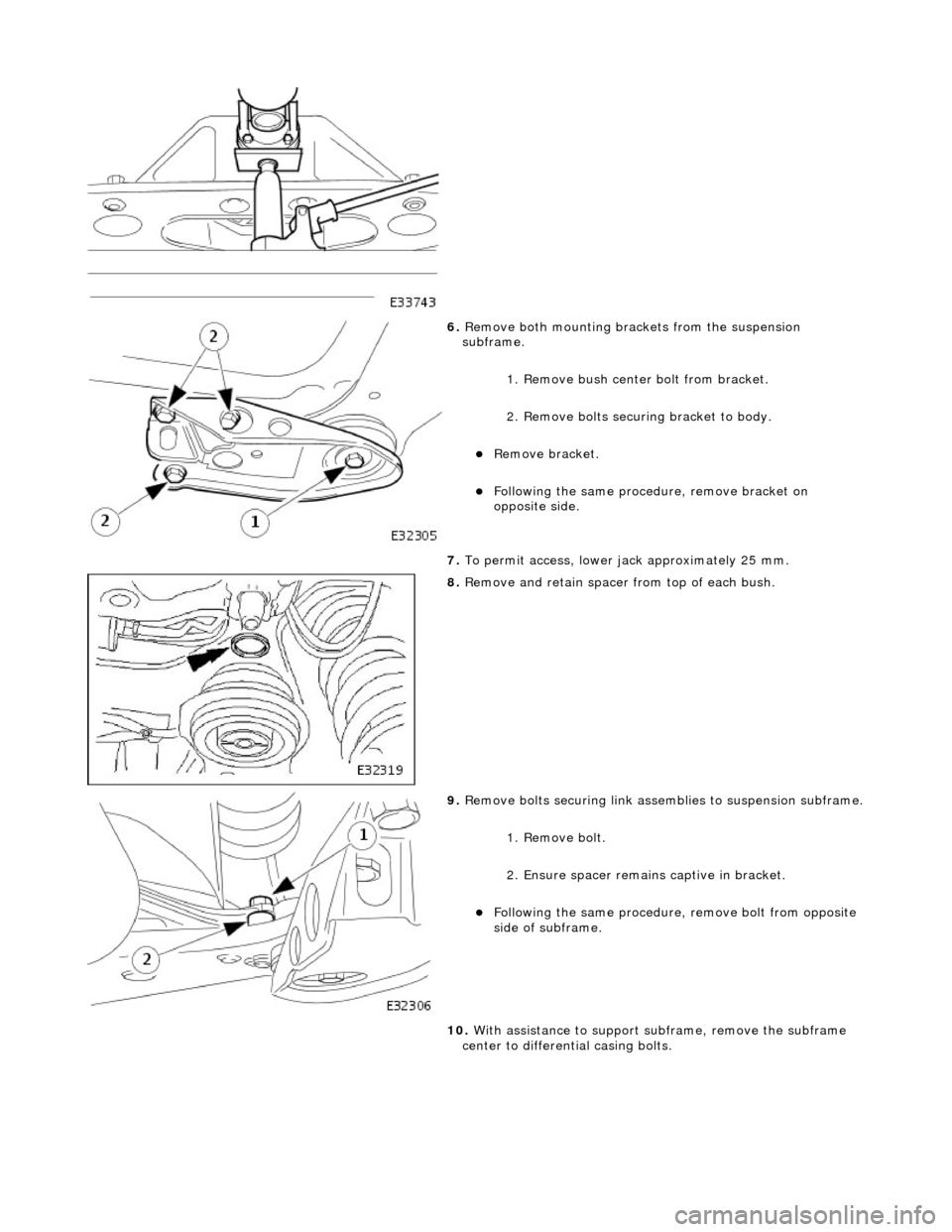
6. Remove both mounting brac kets from the suspension
subframe.
1. Remove bush center bolt from bracket.
2. Remove bolts securi ng bracket to body.
Remove bracket.
Following the same procedure, remove bracket on
opposite side.
7. To permit access, lower jack approximately 25 mm.
8. Remove and retain spacer from top of each bush.
9. Remove bolts securing link assemblies to suspension subframe.
1. Remove bolt.
2. Ensure spacer remain s captive in bracket.
Following the same procedure, remove bolt from opposite
side of subframe.
10. With assistance to support su bframe, remove the subframe
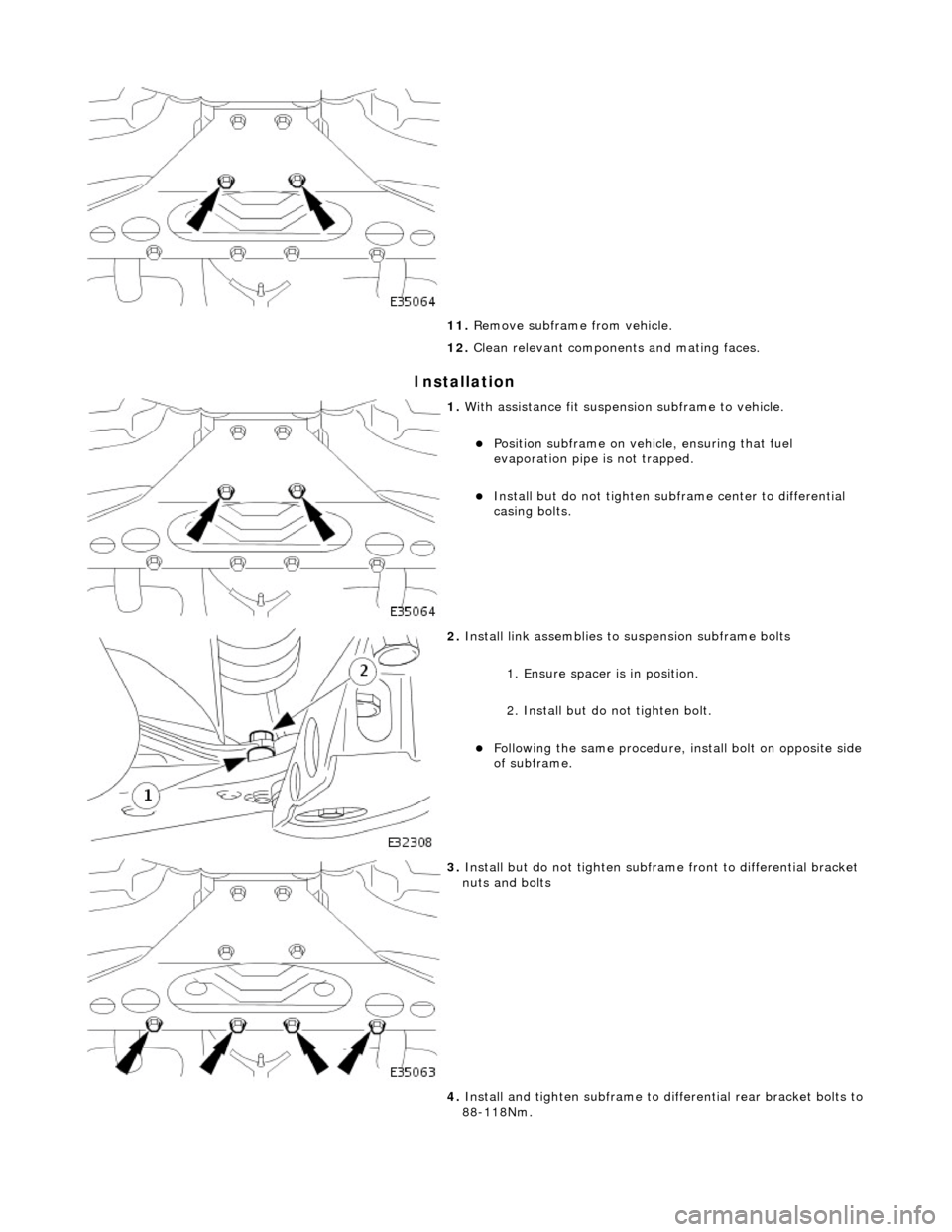
center to differential casing bolts.
Page 2483 of 2490
Installation
11. Remove subframe from vehicle.
12. Clean relevant components and mating faces.
1. With assistance fit suspension subframe to vehicle.
Position subframe on vehi cle, ensuring that fuel
evaporation pipe is not trapped.
Install but do not tighten sub frame center to differential
casing bolts.
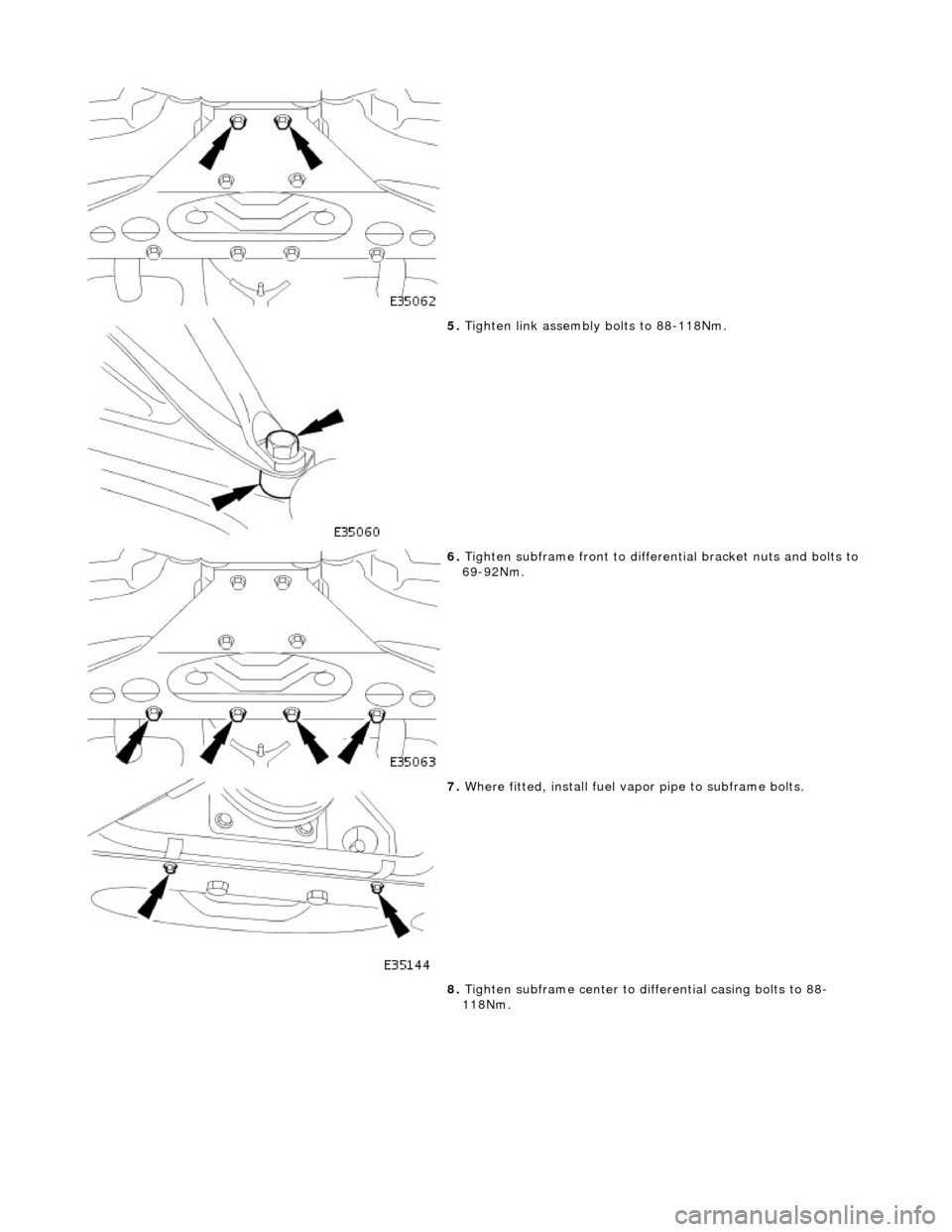
2. Install link assemblies to suspension subframe bolts
1. Ensure spacer is in position.
2. Install but do not tighten bolt.
Following the same procedure, in stall bolt on opposite side
of subframe.
3. Install but do not tighten subframe front to differential bracket
nuts and bolts
4. Install and tighten sub frame to differential rear bracket bolts to
88-118Nm.
Page 2484 of 2490
5. Tighten link assembly bolts to 88-118Nm.
6. Tighten subframe front to differential bracket nuts and bolts to
69-92Nm.
7. Where fitted, install fuel vapo r pipe to subframe bolts.
8. Tighten subframe center to di fferential casing bolts to 88-
118Nm.
