JAGUAR X308 1998 2.G Owner's Manual
X308 1998 2.G
JAGUAR
JAGUAR
https://www.carmanualsonline.info/img/21/7640/w960_7640-0.png
JAGUAR X308 1998 2.G Owner's Manual
Page 1843 of 2490
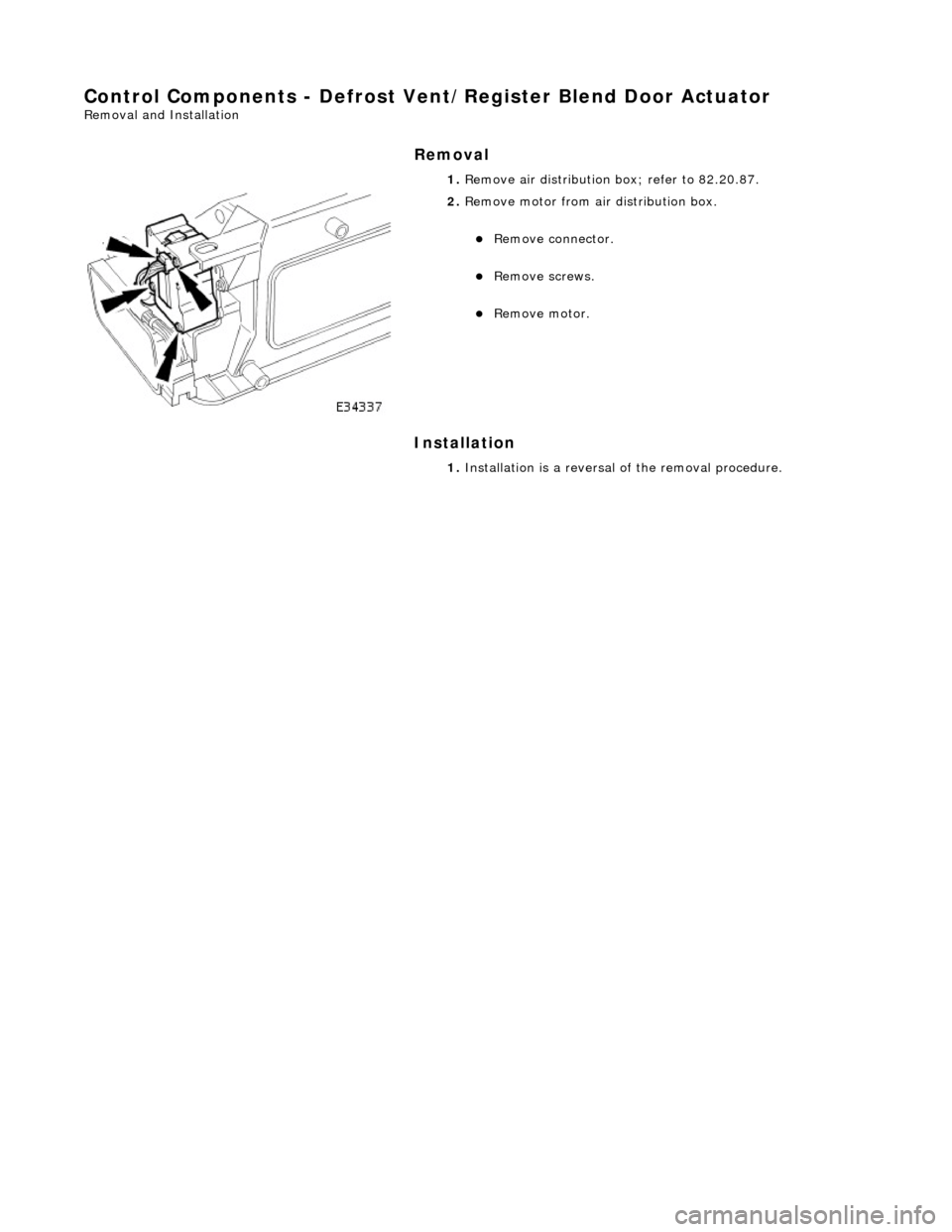
Control Components - Defrost Vent/Register Blend Door Actuator
Removal and Installation
Removal
Installation
1.
Remove air distribution box; refer to 82.20.87.
2. Remove motor from air distribution box.
Remove connector.
Remove screws.
Remove motor.
1. Installation is a reversal of the removal procedure.
Page 1844 of 2490
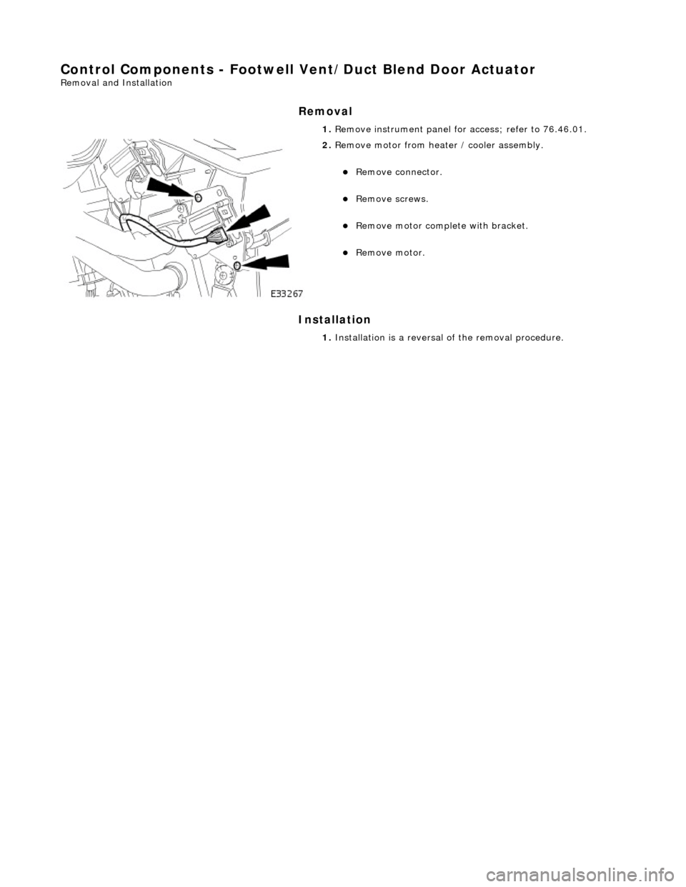
Control Components - Footwell Vent/Duct Blend Door Actuator
Removal and Installation
Removal
Installation
1.
Remove instrument panel for access; refer to 76.46.01.
2. Remove motor from heater / cooler assembly.
Remove connector.
Remove screws.
Remove motor complete with bracket.
Remove motor.
1. Installation is a reversal of the removal procedure.
Page 1845 of 2490
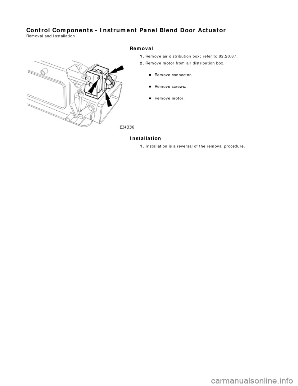
Control Components - Instrument Panel Blend Door Actuator
Removal and Installation
Removal
Installation
1.
Remove air distribution box; refer to 82.20.87.
2. Remove motor from air distribution box.
Remove connector.
Remove screws.
Remove motor.
1. Installation is a reversal of the removal procedure.
Page 1904 of 2490
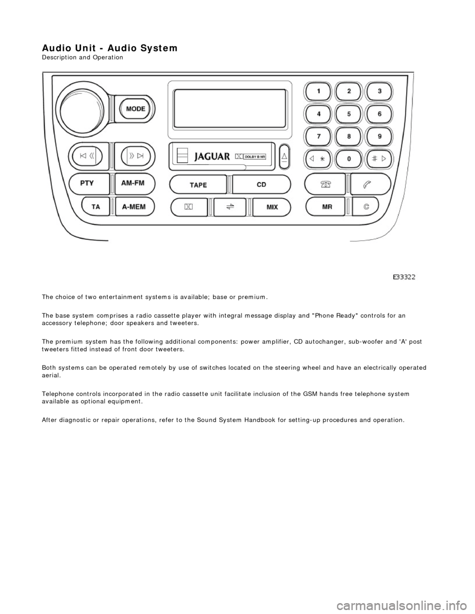
Audio Unit - Audio System
Description and Operation
The choice of two entertainment system s is available; base or premium.
The base system comprises a radio cassette player with in tegral message display and "Phone Ready" controls for an
accessory telephone; door speakers and tweeters.
The premium system has the following additional components: power amplifier, CD autochanger, sub-woofer and 'A' post
tweeters fitted instead of front door tweeters.
Both systems can be operated remotely by use of switches loca ted on the steering wheel and have an electrically operated
aerial.
Telephone controls incorporated in the ra dio cassette unit facilitate inclusion of the GSM hands free telephone system
available as optional equipment.
After diagnostic or repair operations, refer to the Sound System Handbook for setting-up procedures and operation.
Page 1910 of 2490
Speakers - Speakers
Description and Operation
Speaker Location
Parts List
ItemPart NumberDescription
1—Door Speaker
2—Front Door Tweeter (Base System)
3—Rear Door Tweeter
4—CD Autochanger (P remium System)
5—Amplifier (Premium System)
6—Sub-woofer (Premium System)
7—'A' Post Tweeter (Premium System)
Page 1914 of 2490
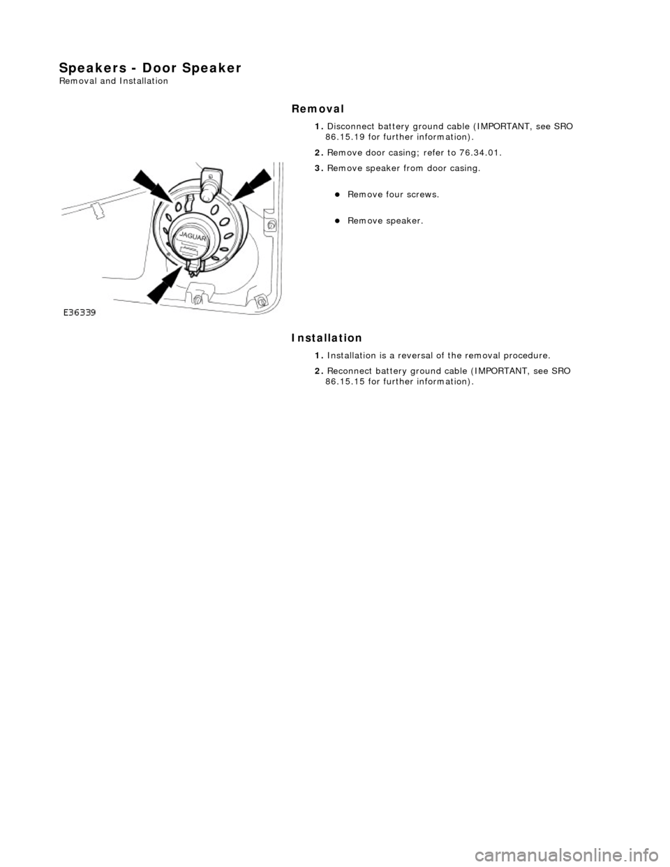
Speakers - Door Speaker
Removal and Installation
Removal
Installation
1.
Disconnect battery ground cable (IMPORTANT, see SRO
86.15.19 for further information).
2. Remove door casing; refer to 76.34.01.
3. Remove speaker from door casing.
Remove four screws.
Remove speaker.
1. Installation is a reversal of the removal procedure.
2. Reconnect battery ground cable (IMPORTANT, see SRO
86.15.15 for further information).
Page 1915 of 2490
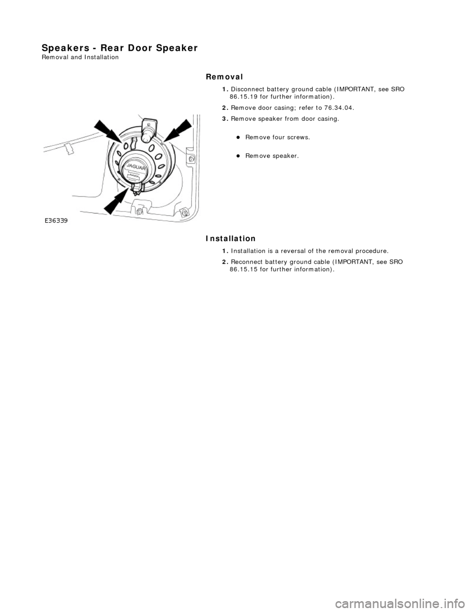
Speakers - Rear Door Speaker
Removal and Installation
Removal
Installation
1.
Disconnect battery ground cable (IMPORTANT, see SRO
86.15.19 for further information).
2. Remove door casing; refer to 76.34.04.
3. Remove speaker from door casing.
Remove four screws.
Remove speaker.
1. Installation is a reversal of the removal procedure.
2. Reconnect battery ground cable (IMPORTANT, see SRO
86.15.15 for further information).
Page 1916 of 2490
Speakers - Rear Door Tweeter Speaker
Removal and Installation
Removal
Installation
1.
Remove rear door casing fo r access; refer to 76.34.04.
2. Remove tweeter.
Disconnect connector.
Simultaneously depress retain ing clips and slide tweeter
away from location.
1. CAUTION: Misalignment of tw eeter during installation
could result in the retaining clips being broken. Position tweeter in
front of location and push into position.
Installation is a reversal of the removal procedure.
Page 1961 of 2490
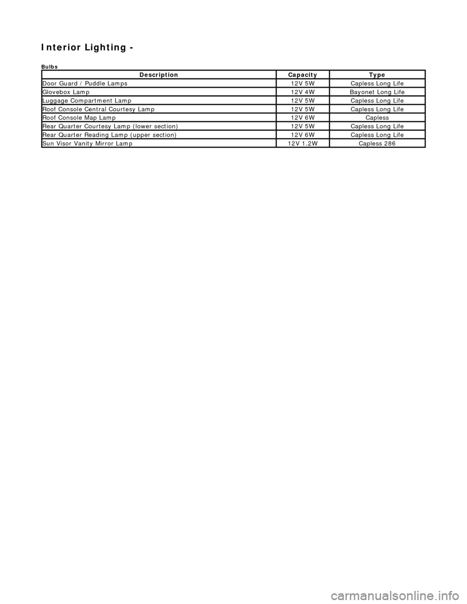
Interior Lighting -
Bulbs
DescriptionCapacityType
Door Guard / Puddle Lamps12V 5WCapless Long Life
Glovebox Lamp12V 4WBayonet Long Life
Luggage Compartment Lamp12V 5WCapless Long Life
Roof Console Central Courtesy Lamp12V 5WCapless Long Life
Roof Console Map Lamp12V 6WCapless
Rear Quarter Courtesy Lamp (lower section)12V 5WCapless Long Life
Rear Quarter Reading Lamp (upper section)12V 6WCapless Long Life
Sun Visor Vanity Mirror Lamp12V 1.2WCapless 286
Page 1962 of 2490
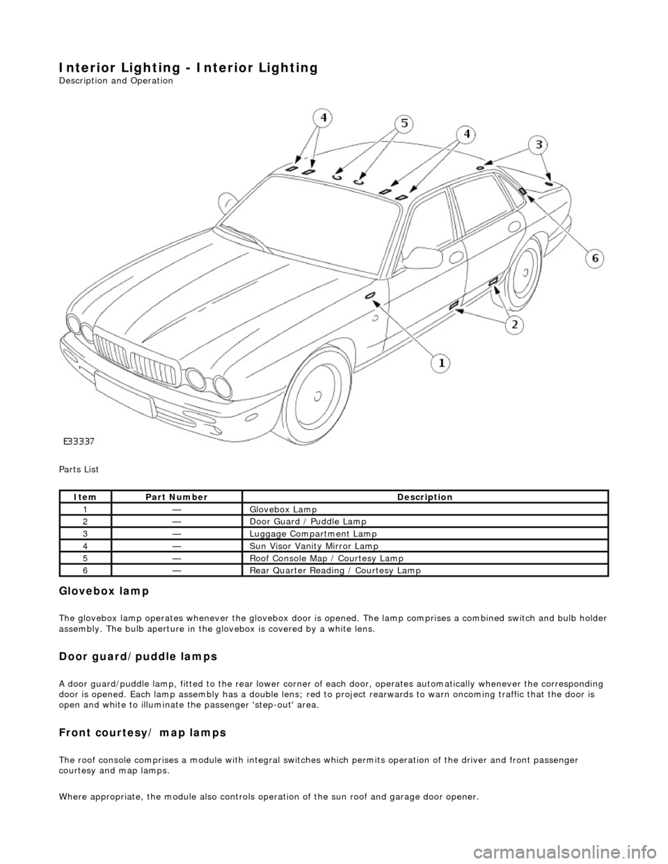
Interior Lighting - Interior Lighting
Description and Operation
Parts List
Glovebox lamp
The glovebox lamp operates whenever the glovebox door is opened. The lamp comprises a combined switch and bulb holder assembly. The bulb aperture in the glovebox is covered by a white lens.
Door guard/puddle lamps
A door guard/puddle lamp, fitted to the rear lower corner of each door, operates automatically whenever the corresponding
door is opened. Each lamp assembly has a double lens; red to project rearwards to warn oncoming traffic that the door is
open and white to illuminate the passenger 'step-out' area.
Front courtesy/ map lamps
The roof console comprises a module with integral switches which permits operation of the dr iver and front passenger
courtesy and map lamps.
Where appropriate, the module also controls operation of the su n roof and garage door opener.
ItemPart NumberDescription
1—Glovebox Lamp
2—Door Guard / Puddle Lamp
3—Luggage Compartment Lamp
4—Sun Visor Vanity Mirror Lamp
5—Roof Console Map / Courtesy Lamp
6—Rear Quarter Reading / Courtesy Lamp
