light JAGUAR X308 1998 2.G Owner's Manual
[x] Cancel search | Manufacturer: JAGUAR, Model Year: 1998, Model line: X308, Model: JAGUAR X308 1998 2.GPages: 2490, PDF Size: 69.81 MB
Page 414 of 2490
Hydrau
lic Brake Actuation - Brake Pedal and Bracket
Re
mo
val and Installation
Remov
a
l
• C
A
UTIONS:
Replacement of nuts and bolts: Various thread-locking de vices are used on nuts and bolts throughout the vehicle.
These devices restrict the number of times a nut or bolt can be used. See section 100-00 for information.
Remove brake fluid spilla ge immediately from paint work, with clean water.
In
stallation
1.
Position vehicl
e on a four-post lift.
2. Open hood and fit suitable pa intwork protection equipment.
3. Disconnect battery ground cabl e. (IMPORTANT, see 86.15.19
for further information).
4. Remove engine compartment rear cover. Refer to operation
76.11.35.
5. Remove pedal housing, brake booster and master cylinder
assembly. Refer to operation 70.35.39.
6. Remove brake booster and master cylinder assembly. Refer to
operation 70.50.18.
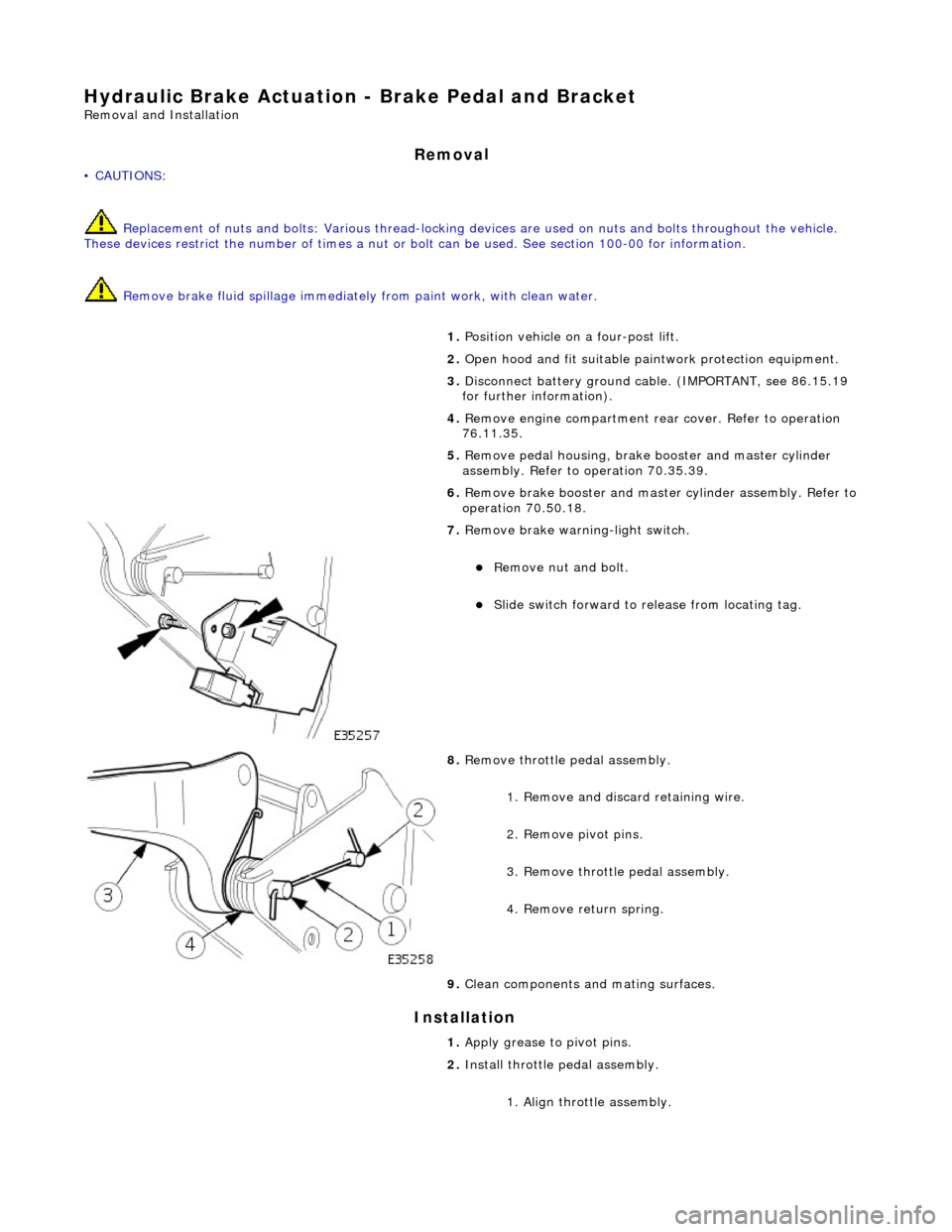
7. Remove brake wa
rning-light switch.
Remove n
u
t and bolt.
Slide sw
itch forward to release from locating tag.
8. Re
move throttle pedal assembly.
1. Remove and discard retaining wire.
2. Remove pivot pins.
3. Remove throttle pedal assembly.
4. Remove return spring.
9. Clean components and mating surfaces.
1. Apply grease to pivot pins.
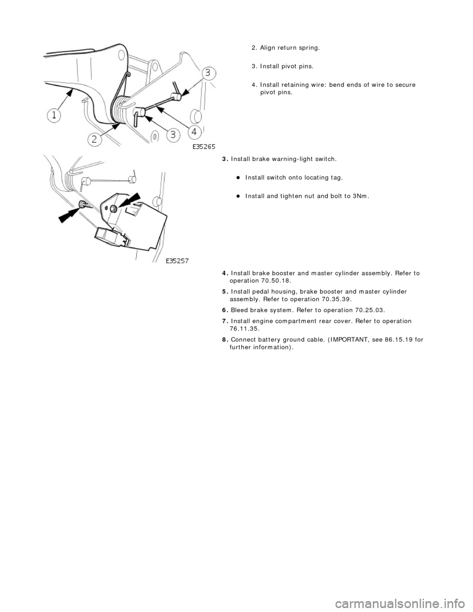
2. Install throttle pedal assembly.
1. Align throttle assembly.
Page 415 of 2490
2
. Align return spring.
3. Install pivot pins.
4. Install retaining wire: bend ends of wire to secure
pivot pins.
3. Inst
all brake warning-light switch.
Inst
all switch onto locating tag.
Install and tigh
ten nut and bolt to 3Nm.
4. Install brake booster and master cylinder assembly. Refer to
operation 70.50.18.
5. Install pedal housing, brake booster and master cylinder
assembly. Refer to operation 70.35.39.
6. Bleed brake system. Refer to operation 70.25.03.
7. Install engine compartment rear cover. Refer to operation
76.11.35.
8. Connect battery ground cable. (IMPORTANT, see 86.15.19 for
further information).
Page 432 of 2490
It is a reciprocating two
-circuit pu
mp in which one brake circuit is as signed to each pump circuit.
It supplies th
e fluid pressure and vo
lume to supply the brake circuits under ABS and Traction control.
The pump is driven by an electri
c motor, with the pump
housing incorporating two lo w pressure accumulators and
damping chambers for each brake circuit.
The ac cu
mulator stores the pressure and smooths out the output pu
lses from the pump.
ABS Warning Lamp
The sys
tem will be set in a fail-safe mode if a problem is de
tected; a warning lamp on the instrument panel will notify the
driver there is a problem.
Anti-Lock Braking Sy
stem (ABS)
The AB
S components are combined with
an hydraulic booster and a tandem master cylinder to provide a two circuit braking
system. The system comprises, four wheel speed sensor s, a brake control modulator and an ABS warning lamp.
Should a wheel start to lock-up during braking a signal tr ansmitted from the wheel speed sensor to the brake control
modulator will start the hydraulic pump. The brake control modula tor will close the input valve of the line connected to the
locked-wheel to stop any increase in fluid pressure to the br ake caliper. If this fails to prevent the wheel locking, the
pressure in the caliper will be decreased by opening the return valve until th e wheel starts accelerating again. The fluid
pressure from the return va lve is directed into the low pressure accumulator, housed in the pump.
From the low pressure accumulator, fl uid is pumped through the damping cham ber to the brake master cylinder. The
pressure to the brake caliper will then be increased in small steps to maintain maximum adhesion between the tire and road
surface. This is achieved by closing the return valve, and opening the input valve and using the hydraulic pump to increase
the pressure.
Although the system senses all four wheels independently, the rear wheels are regulated as a pair. If a sensor on a rear
wheel detects a wheel decelerating rapidly, then the fluid pressure to both wheels is reduced. The fluid pressure is then
dictated by the wheel having the lowe st adhesion with the road surface.
The ABS system will be set in a fail-safe mode if a problem is detected; a warn ing lamp on the instrument panel will notify
the driver there is a problem. The brake system will still operate conventionally and with the same standard of performance
as a vehicle not equipped with ABS.
Automa tic Stability Control (ASC)
Th
e ASC utilizes the ABS sensing arrangement to provide the maximum traction force to propel the vehicle.
The ASC is switched on when the engine is started. The system can be switched off by pressing the 'ASC OFF' (the switched
is marked 'TRAC OFF' on vehicles fitted with traction control). The switch, which is situated in the center console switchpack,
lights up to warn that the system is sw itched off. An 'ASC' amber warning light flashes on the instrument panel when the
system detects a spinning wheel.
The ASC system uses engine intervention to reduce the torque delivered to the drive wheels to prevent them spinning.
Engine torque is re duced in three ways:
The
throttle is moved towards the closed position.
The ignition is retarded. F
u
el is cut-off at the cylinder injectors.
Wheel spin is detected by the wheel sp eed sensors and communicated to the AB S/TCCM. The ABS/TCCM uses information
from the controller area network (CAN) to calculate the torque that the engine should produce to stop the wheel spinning.
Torque reductions are then requested from the engine control module (ECM ) through the CAN. The throttle is then
positioned to provide the target torque, which has been calculated to prevent wheel spin. During the transient phase of
torque reduction the fuel is cut-off and th e ignition retarded Both the fuel cut-off an d ignition retard will be restored to
normal when the throttle is set to its new position.
The ASC uses a brake control modulator with six solenoid va lves: three normally open inlet valves and three normally
Page 433 of 2490
clos
ed outlet valves.
Traction Control
Trac
tion control has the same capabilities as ASC but with th
e added ability to actuate the brakes of the spinning wheel.
This enhances ASC by improving acceleration particularly on surfaces with uneven friction , e.g. one wheel on ice the other
on tarmac.
When wheelspin occurs, brake line pressure to the slipping wheel is generated, to operate that wheel's brake. The BCM
achieves this by closing the cut-off solenoid valve and oper ating the hydraulic pump. Brake fluid is then drawn from the
reservoir through the non-actuated mast er cylinder to the brake caliper.
A 'TRAC' amber warning light flashes on the instrument panel when the system detects a spinning wheel.
The traction control system uses a brake control modulator with nine solenoid valv es: four normally open inlet valves and
four normally closed outlet valves and one special isolating va lve. The outlet valves control the brakes of each each rear
wheel individually on the traction control system.
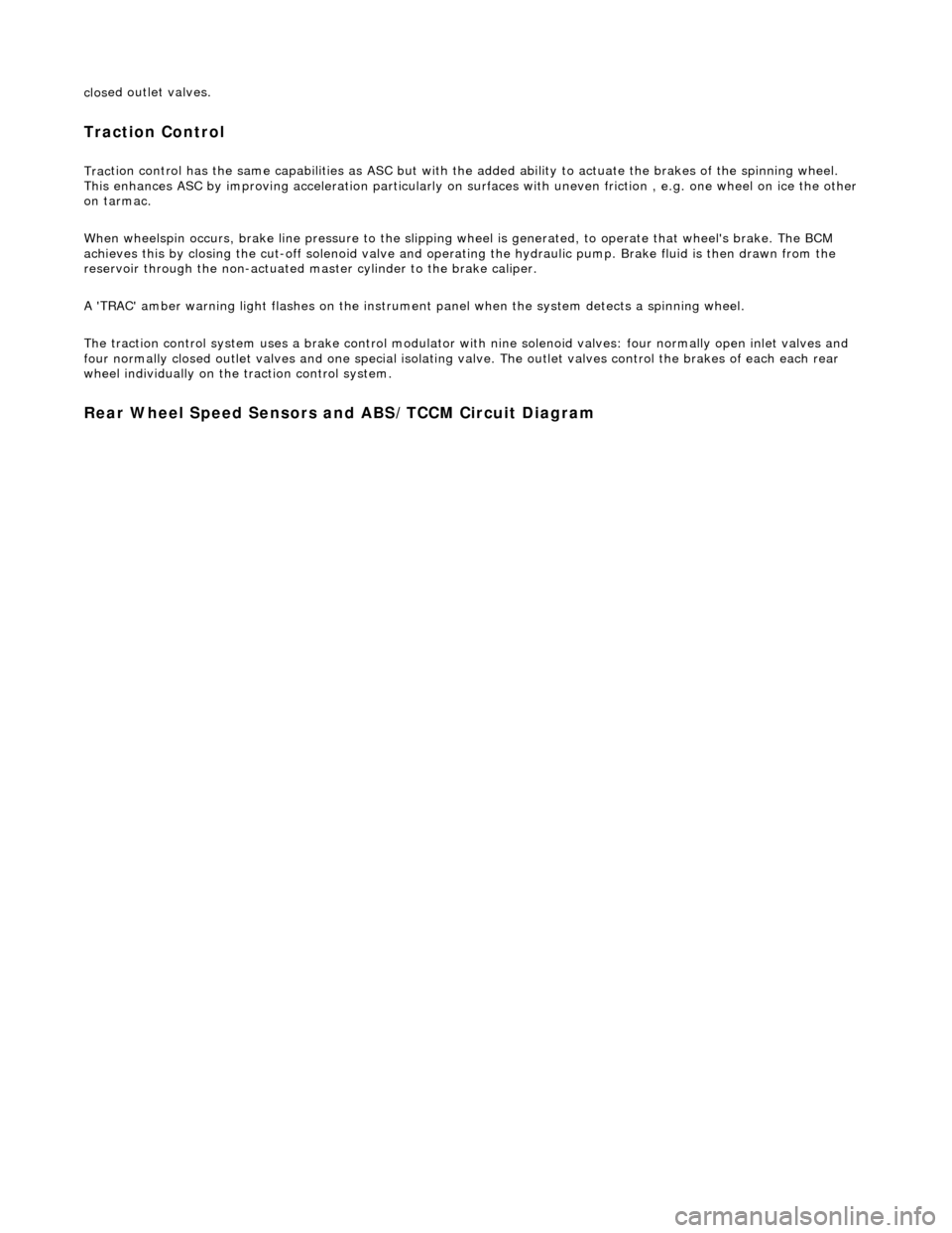
Rear Wheel Speed Senso
rs and ABS/TCCM Circuit Diagram
Page 435 of 2490
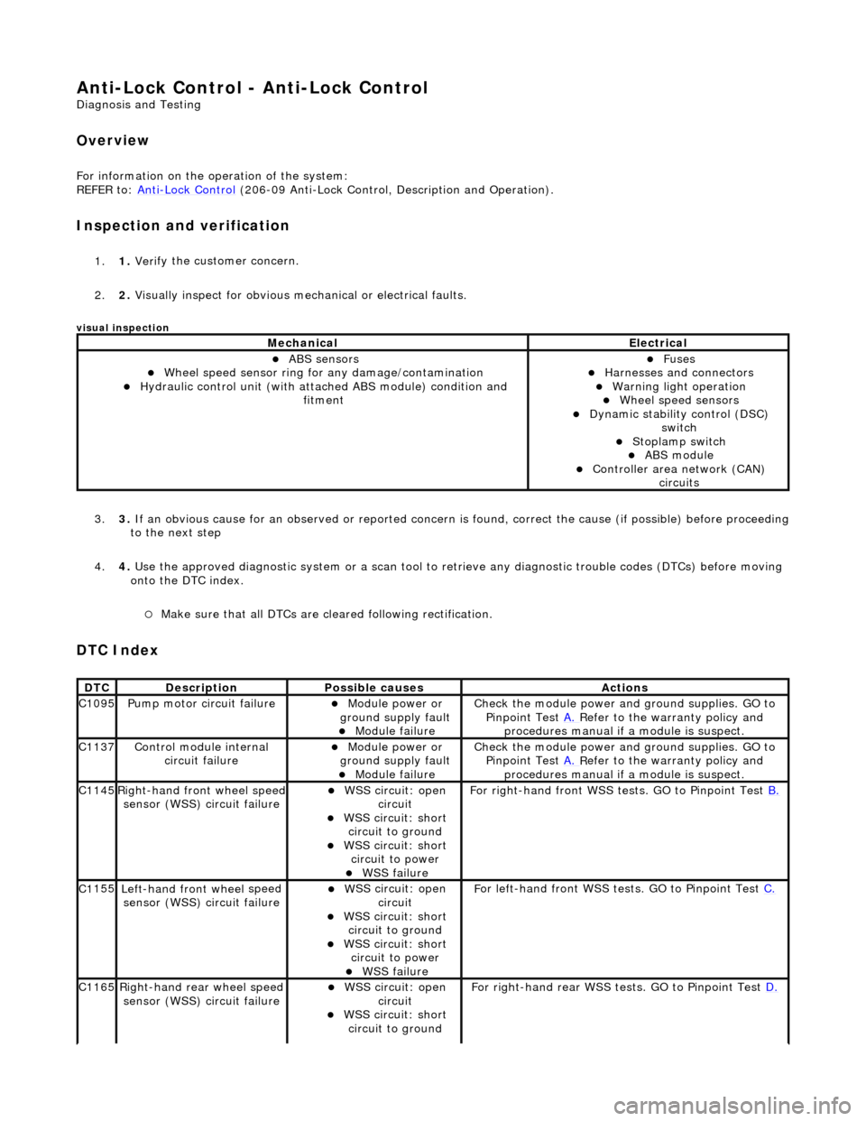
Anti-Lock Control - Anti-Lock Control
D
iagnosis and Testing
Ov
erview
Fo
r information on the operation of the system:
REFER to: Anti
-Lock Control
(206-09 Anti-Lock Control, Description and Operation).
I
nspection and verification
1.
1. Veri
fy the customer concern.
2. 2. Visually inspect for obvious mech anical or electrical faults.
visual insp
ection
3.
3. If
an obvious cause for an observed or
reported concern is found, correct th e cause (if possible) before proceeding
to the next step
4. 4. Use the approved diagnostic system or a scan tool to retrieve any diagnostic trouble codes (DTCs) before moving
onto the DTC index.
Make sure that
all DTCs are cleared following rectification.
DTC Index
MechanicalElectrical
ABS se
nsors
W
heel speed sensor ring for
any damage/contamination
Hydrauli
c control unit (with attached ABS module) condition and
fitment
F
uses
Harnes
ses and connectors
War
ning light operation
Wh
eel speed sensors
Dynam
ic stability control (DSC)
switch
Stoplamp switch
ABS module Con
troller area network (CAN)
circuits
DT
C
De
scription
Possib
le causes
Acti
ons
C1
095
Pump mo
tor circuit failure
Module power or
gr
ound supply fault
Module
failure
Check the modu
le power and
ground supplies. GO to
Pinpoint Test A.
R
efer to the warranty policy and
procedures manual if a module is suspect.
C1
137
Control modu
le internal
circuit failure
Module power or
gr
ound supply fault
Module
failure
Check the modu
le power and
ground supplies. GO to
Pinpoint Test A.
R
efer to the warranty policy and
procedures manual if a module is suspect.
C1
145
Right
-hand front wheel speed
sensor (WSS) circuit failure
W
SS circuit: open
circuit
W
SS circuit: short
circuit to ground
W
SS circuit: short
circuit to power
WSS
failure
F
or right-hand front WSS tests. GO to Pinpoint Test
B.
C1
155
Left-hand front wheel
speed
sensor (WSS) circuit failure
W
SS circuit: open
circuit
W
SS circuit: short
circuit to ground
W
SS circuit: short
circuit to power
WSS
failure
F
or left-hand front WSS tests. GO to Pinpoint Test
C.
C1
165
Ri
ght-hand rear wheel speed
sensor (WSS) circuit failure
W
SS circuit: open
circuit
W
SS circuit: short
circuit to ground
F
or right-hand rear WSS test
s. GO to Pinpoint Test D.
Page 462 of 2490
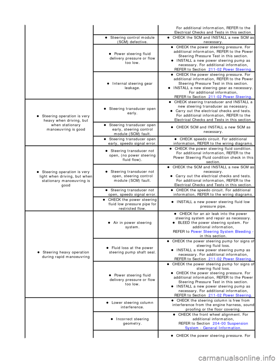
Fo
r additional information, REFER to the
Electrical Checks and Tests in this section.
Steering control
module
(SCM) defective.
CHECK
the SCM and INSTALL a new SCM as
necessary.
Power steeri ng f
luid
delivery pressure or flow too low.
CHECK
the power stee
ring pressure. For
additional information, REFER to the Power Steering Pressure Test in this section.
INSTALL a ne
w power steering pump as
necessary. For additi onal information,
REFER to Section 211
-0 2
Power Steering
.
Internal steering gear
leakage.
CHECK
the power stee
ring pressure. For
additional information, REFER to the Power Steering Pressure Test in this section.
INSTALL a ne
w steering
gear as necessary.
For additional information,
REFER to Section 211
-0 2
Power Steering
.
Steeri
ng operati
on is very
heavy when driving, but when stationary
manoeuvring is good
Steering transducer open earl
y.
CHECK
steering transducer and INSTALL a
new steering transducer as necessary.
Carry out th
e electrical checks and tests.
For additional information, REFER to the
Electrical Checks and Tests in this section.
Steering transducer open
early,
steering control
module (SCM) fault.
CHECK
SCM and INSTALL a new SCM as
necessary.
Steering transducer open
earl
y, speedo signal error.
CHECK
speedo
circui
t. For additional
information, REFER to the wiring diagrams.
Steeri ng operati
on is very
light when driving, but when
stationary manoeuvring is good
Steering transducer not
o
pen, (no power steering
fluid flow).
CHECK
the power steering fluid condition.
For additional information, REFER to the
Power Steering Fluid condition check in this section.
Steering transducer not o
pen, steering control
module (SCM) fault.
CHECK
the SCM and INSTALL a new SCM as
necessary.
Carry out th
e electrical checks and tests.
For additional information, REFER to the
Electrical Checks and Tests in this section.
Steering transducer not
o
pen, speedo signal error.
CHECK
the speedo circ
uit. For additional
information, REFER to the wiring diagrams.
CHECK
the power steering
fluid low pressure pipe for restricted flow.
INSTALL a ne
w power steering fluid low
pressure pipe.
S t
eering heavy operation
during rapid manoeuvring
Ai r i
n power steering
system.
CHECK for an air l
eak into the power
steering system and re pair as necessary.
BLEED the
power steering system. For
additional information,
REFER to Power Steering System Bleeding
- in t hi
s section.
Fluid loss at the power
steering pump shaft seal.
CHECK the power steer
ing pump for signs o
f steering fl
ui
d loss.
INST
ALL a ne
w power steering pump as
necessary. For additi onal information,
REFER to Section 211
-0 2
Power Steering
.
Power steeri
ng f
luid
delivery pressure or flow too low.
CHECK the power steer
ing pump for signs o
f steering fl
ui
d loss.
CHECK
the power stee
ring pressure. For
additional information, REFER to the Power Steering Pressure Test in this section.
INSTALL a ne
w power steering pump as
necessary. For additi onal information,
REFER to Section 211
-02
Power Steering
.
Lower steeri
ng col
umn
interference.
CHECK
the steering co
lumn is free from
interference from the en gine harness, sound
proofing or the floor covering.
Incorrect steering geometry. CHE
CK the front wheel alignment. For
additional information,
REFER to Section 204
-00 Sus
pension
Sy
ste
m
- General
Information
.
CHECK
the power stee
ring pressure. For
Page 463 of 2490
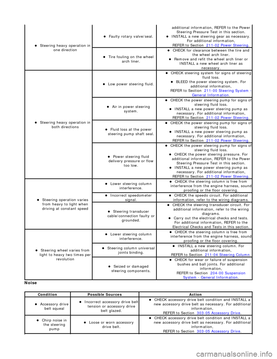
No
ise
S
teering heavy operation in
one direction
F
aulty rotary valve/seal.
addi
tional information, REFER to the Power
Steering Pressure Test in this section.
INST
ALL a new steering
gear as necessary.
For additional information,
REFER to Section 211
-0
2 Power Steering
.
Ti
re fouling on the wheel
arch liner.
CHECK for
clearance be
tween the tire and
the wheel arch liner.
R
emove and refit the wheel arch liner or
INSTALL a new wheel arch liner as necessary.
S
teering heavy operation in
both directions
Low power steer
ing fluid.
CHE
CK steering system
for signs of steering
fluid loss.
BLEE
D the power steering system. For
additional information,
REFER to Section 211
-0
0 Steering System
- General Informati
on
.
Ai
r in power steering
system.
CHECK
the power steering pump for signs o
f steering fl
uid loss.
INST
ALL a new power steering pump as
necessary. For additi onal information,
REFER to Section 211
-0
2 Power Steering
.
Fluid loss at the power
steering pump shaft seal.
CHECK
the power steering pump for signs o
f steering fl
uid loss.
INST
ALL a new power steering pump as
necessary. For additi onal information,
REFER to Section 211
-0
2 Power Steering
.
Power steeri
ng fluid
delivery pressure or flow too low.
CHECK
the power steering pump for signs o
f steering fl
uid loss.
CHECK
the power stee
ring pressure. For
additional information, REFER to the Power Steering Pressure Test in this section.
INST
ALL a new power steering pump as
necessary. For additi onal information,
REFER to Section 211
-0
2 Power Steering
.
Steeri
ng operation varies
from heavy to light when
driving at constant speed
Lower steeri
ng column
interference.
CHECK
the steering co
lumn is free from
interference from the en gine harness, sound
proofing or the floor covering.
Incorre
ct sp
eedometer
signal.
CHECK
the speedo circ
uit. For additional
information, refer to the wiring diagrams.
Steeri
ng transducer
cable/connection faulty or grounded.
CHECK
the steering transducer circuit. For
additional information, refer to the wiring diagrams.
Carry ou
t the electrical checks and tests.
For additional information, REFER to the
Electrical Checks and Tests in this section.
Steeri
ng wheel varies from
light to heavy two times per revolution
Lower steeri
ng column
interference.
CHECK
the steering co
lumn is free from
interference from the en gine harness, sound
proofing or the floor covering.
Steeri
ng column universal
joints binding.
IN
STALL a new steering column. For
additional information,
REFER to Section 211
-0
4 Steering Column
.
Seized or damaged
ste
ering components.
CHECK
for wear or failure of suspension
bushes and ball join ts. For additional
information,
REFER to Section 204
-00
Suspension
Sy
stem
- General
Information
.
Cond
ition
Possib
le Sources
Acti
on
Acce
ssory drive
belt squeal
Incorre
ct accessory drive belt
tension or accessory drive belt glazed.
CHECK
accessory drive belt condition and INSTALL a
new accessory drive belt as necessary. For additional
information,
REFER to Section 303
-0
5 Accessory Drive
.
Chir
p noise in
the steering pump
Loose or worn accessory dr
ive belt.
CHECK
accessory drive belt condition and INSTALL a
new accessory drive belt as necessary. For additional
information,
REFER to Section 303
-0
5 Accessory Drive
.
Page 516 of 2490
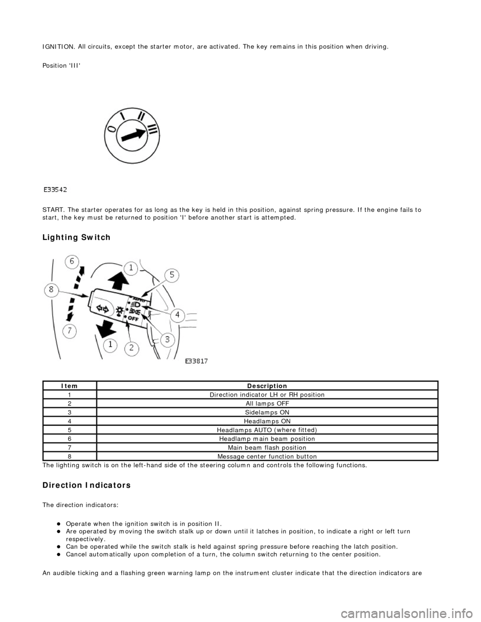
IGNITION.
All circuits, except the star
ter motor, are activated. The key rema ins in this position when driving.
Position 'III'
START. The starter operates for as long as the key is held in this position, ag ainst spring pressure. If the engine fails to
start, the key must be returned to position 'I' befo re another start is attempted.
Lighting Switch
The li
ghting switch is on the left-h
and side of the steering column and controls the following functions.
Direction Indicators
The direction in
dicators:
Operate
when the ignition switch is in position II.
Are operat
ed by movi
ng the switch stalk up or down until it latches in position, to in
dicate a right or left turn
respectively.
Can be o p
erated while the switch stalk is held against
spring pressure before reaching the latch position.
Cancel
automatically upon completion of a turn, the
column switch returning to the center position.
An audible ticking and a flashing green warning lamp on the in strument cluster indicate that the direction indicators are
Ite
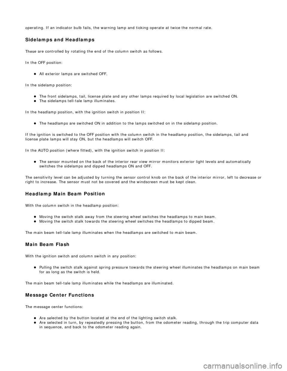
m
De
scr
iption
1D
i
rection indicator LH or RH position
2All lamps OFF
3Side
lamps ON
4Headlamps ON
5Headlamps AUT O
(where fitted)
6He
adlam
p main beam position
7Mai
n
beam flash position
8M
e
ssage center function button
Page 517 of 2490
o
perating. If an indicator bulb fails, the warning
lamp and ticking operate at twice the normal rate.
Sidelam
ps and Headlamps
Thes
e are controlled by rotating the end of the column switch as follows.
In the OFF position:
All
exterior lamps are switched OFF.
In the sidelamp position:
The front
sidelamps, tail, license plate and any other la
mps required by local legislation are switched ON.
The
sidelamps tell-tale lamp illuminates.
In the headlamp position, with the ignition switch in position II:
The h
eadlamps are switched ON in addition to the lamps switched on in the sidelamp position.
If the ignition is switched to the OFF position with the column switch in the headlamp position, the sidelamps, tail and
license plate lamps will stay ON, but the headlamps will switch OFF.
In the AUTO position (where fitted), with the ignition switch in position II:
Th
e sensor mounted on the back of the interior rear view
mirror monitors exterior light levels and automatically
switches the sidelamps and di pped headlamps ON and OFF.
The sensitivity level can be adjusted by turn ing the sensor control knob on the back of the interior mirror, left to decrease or
right to increase. The sensor must not be covered and the windscreen must be kept clean.
Headlamp Main Bea
m Position
Wi
th the column switch in
the headlamp position:
Movin
g the switch stalk away fro
m the steering wheel switches the headlamps to main beam.
Movin
g the switch stalk towards the steering wheel switches the headlamps to dipped beam.
The main beam tell-tale lamp illuminates when the headlamps are switched to main beam.
Ma
in Beam Flash
Wi
th the ignition switch and column switch in any position:
Pulling the
switch stalk agains
t spring pressure towards th e steering wheel illuminates the headlamps on main beam
for as long as the switch is held.
The main beam tell-tale lamp illuminates while the headlamps are illuminated.
M
essage Center Functions
T
he message center functions:
Are se
lected by the button located at the end of the lighting switch stalk.
Are se
lected in turn, by repeatedly pressing the button,
from the odometer reading, through the trip computer data
in sequence, and back to th e odometer reading again.
Page 553 of 2490
1
2.60.48.
12. Install the old bolt which secu red the crankshaft damper, to
allow the crankshaft to be rotated. Use a new bolt on final
installation.
13. The following group of instructions (until stated otherwise)
describe the procedure to rene w the bearing shells in one
connecting rod. Repeat the instructions as necessary.
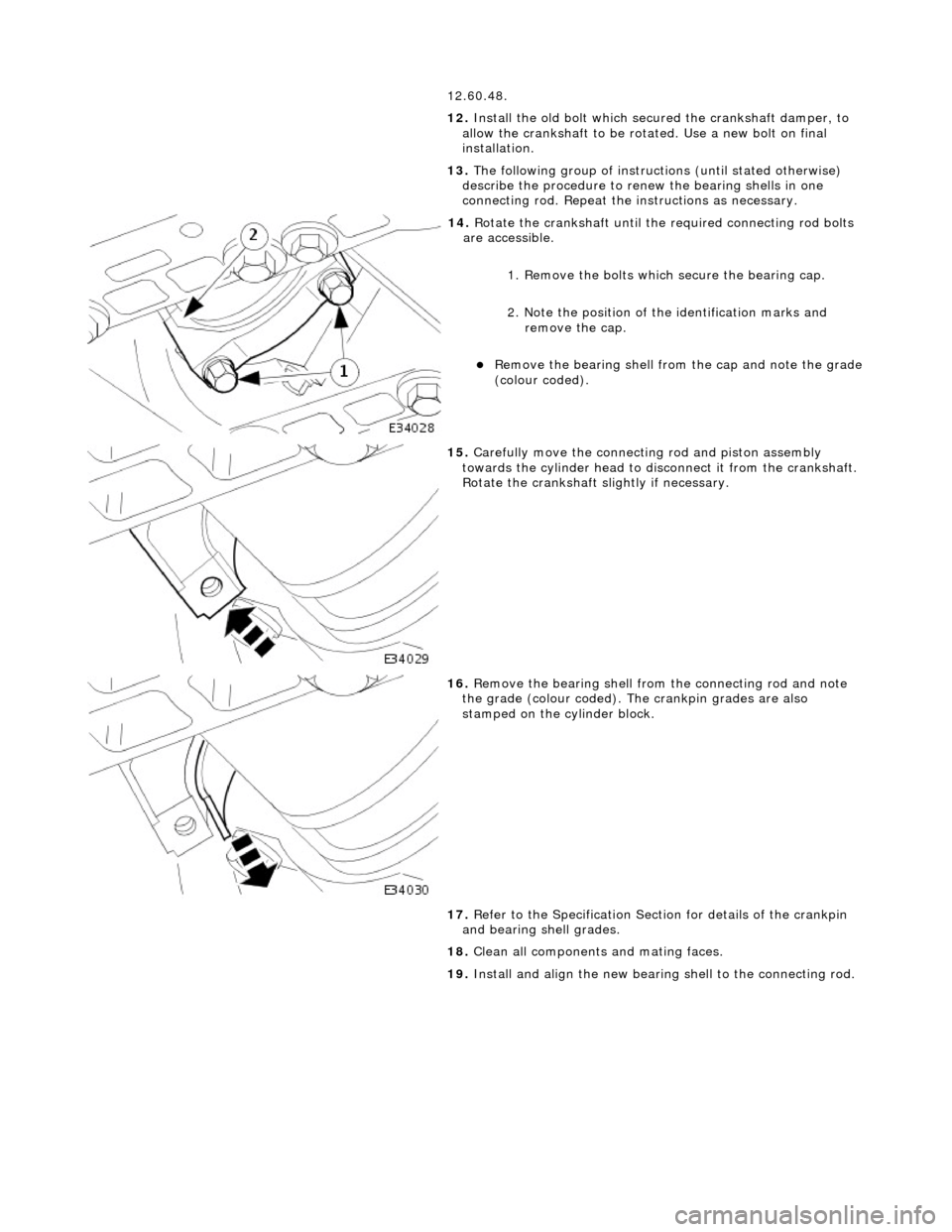
14
.
Rotate the crankshaft until th e required connecting rod bolts
are accessible.
1. Remove the bolts which secure the bearing cap.
2. Note the position of the identification marks and remove the cap.
Remove the
bearing shell from the cap and note the grade
(colour coded).
15
.
Carefully move the connecting rod and piston assembly
towards the cylinder head to di sconnect it from the crankshaft.
Rotate the crankshaft slightly if necessary.
16
.
Remove the bearing shell from the connecting rod and note
the grade (colour coded). The crankpin grades are also
stamped on the cylinder block.
17. Refer to the Specification Sectio n for details of the crankpin
and bearing shell grades.
18. Clean all components and mating faces.
19. Install and align the new bearing shell to the connecting rod.