radio JAGUAR X308 1998 2.G Owner's Manual
[x] Cancel search | Manufacturer: JAGUAR, Model Year: 1998, Model line: X308, Model: JAGUAR X308 1998 2.GPages: 2490, PDF Size: 69.81 MB
Page 1479 of 2490

R .
7. Further installation is the reve rse of the removal procedure.
8. Connect the battery and fit the battery cover.
Reset the radio and the clock.
Page 1483 of 2490

moving the set position of either the shift lever or the selector lever.
3. Tighten the locknuts to the specified torque figure
4. Verify the N setting.
11. Further installation is the reve rse of the removal procedure.
12. Connect the battery and fit the battery cover.
Reset the radio and the clock.
Page 1485 of 2490

3. Connect the battery and fit the battery cover.
Reset the radio and the clock.
Page 1491 of 2490
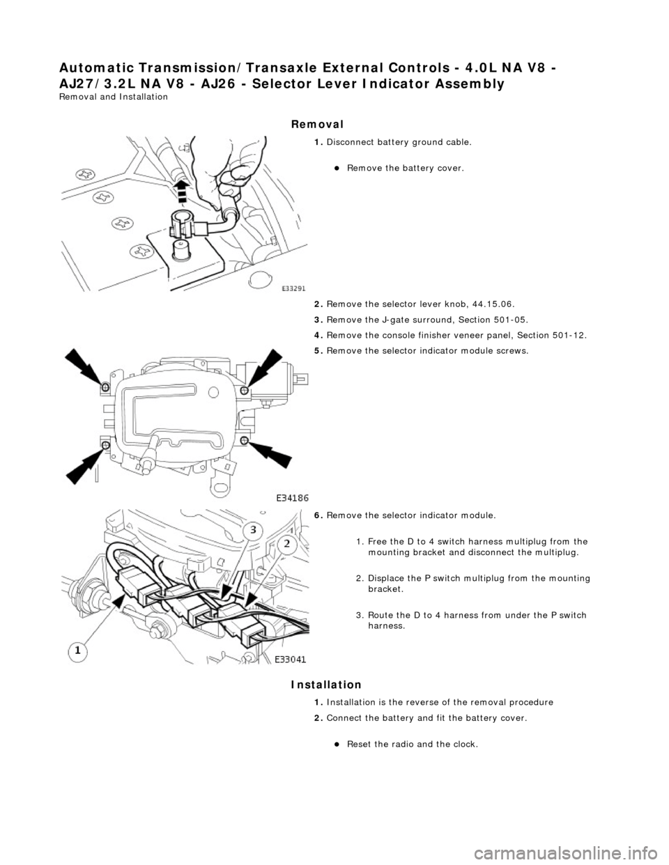
Automatic Transmission/Transaxle External Controls - 4.0L NA V8 -
AJ27/3.2L NA V8 - AJ 26 - Selector Lever Indicator Assembly
Removal and Installation
Removal
Installation
1. Disconnect battery ground cable.
Remove the battery cover.
2. Remove the selector lever knob, 44.15.06.
3. Remove the J-gate surround, Section 501-05.
4. Remove the console finisher ve neer panel, Section 501-12.
5. Remove the selector indicator module screws.
6. Remove the selector indicator module.
1. Free the D to 4 switch harness multiplug from the mounting bracket and disc onnect the multiplug.
2. Displace the P switch multiplug from the mounting bracket.
3. Route the D to 4 harnes s from under the P switch
harness.
1. Installation is the revers e of the removal procedure
2. Connect the battery and fit the battery cover.
Reset the radio and the clock.
Page 1492 of 2490
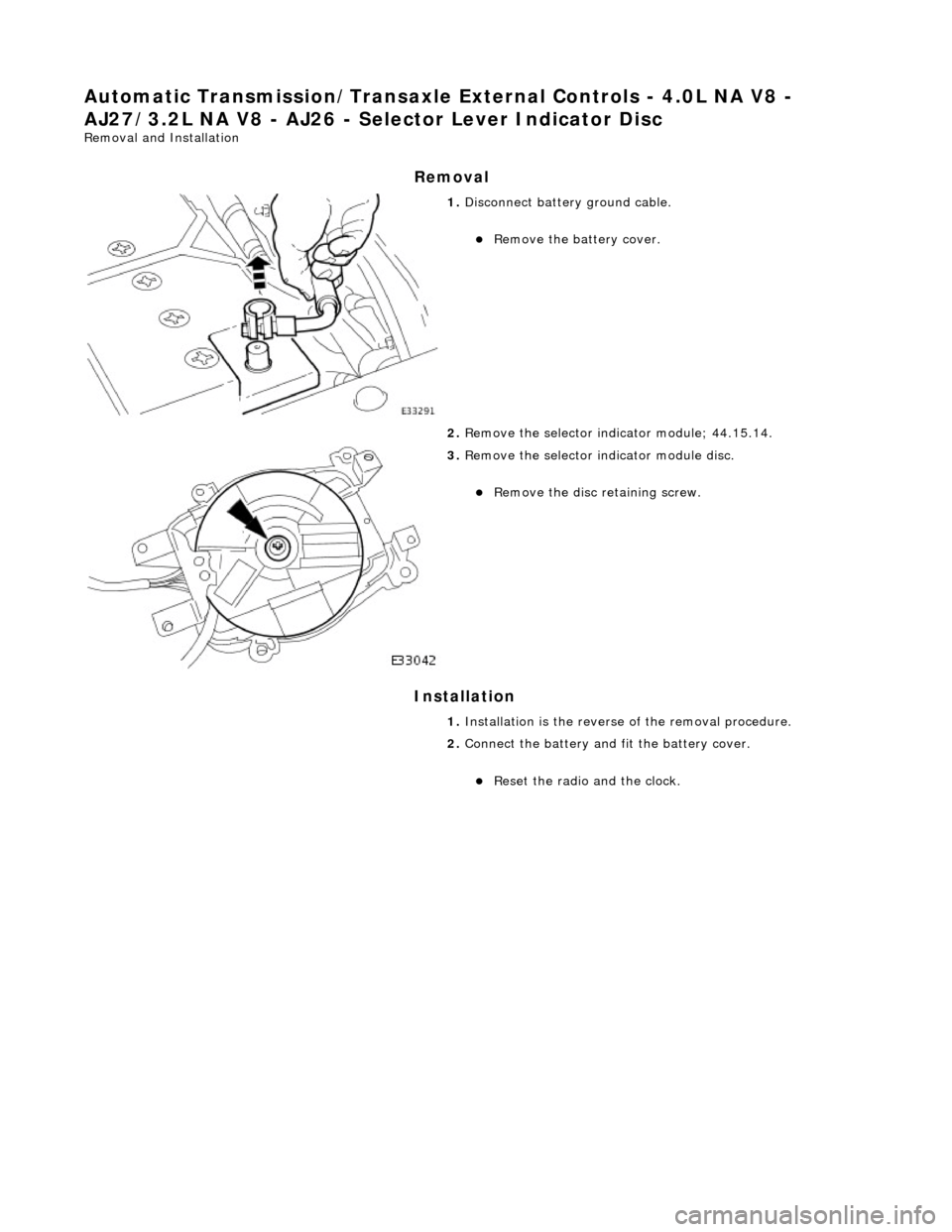
Automatic Transmission/Transaxle External Controls - 4.0L NA V8 -
AJ27/3.2L NA V8 - AJ26 - Se lector Lever Indicator Disc
Removal and Installation
Removal
Installation
1. Disconnect battery ground cable.
Remove the battery cover.
2. Remove the selector indicator module; 44.15.14.
3. Remove the selector indicator module disc.
Remove the disc retaining screw.
1. Installation is th e reverse of the re moval procedure.
2. Connect the battery and fit the battery cover.
Reset the radio and the clock.
Page 1493 of 2490
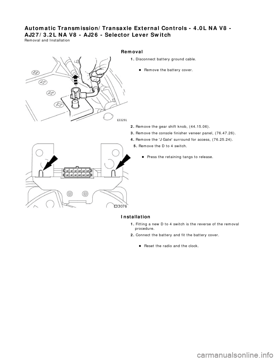
Automatic Transmission/Transaxle External Controls - 4.0L NA V8 -
AJ27/3.2L NA V8 - AJ26 - Selector Lever Switch
Removal and Installation
Removal
Installation
1. Disconnect battery ground cable.
Remove the battery cover.
2. Remove the gear shift knob, (44.15.06).
3. Remove the console finisher veneer panel, (76.47.26).
4. Remove the 'J Gate' surroun d for access, (76.25.24).
5. Remove the D to 4 switch.
Press the retaining tangs to release.
1. Fitting a new D to 4 switch is the reverse of the removal
procedure.
2. Connect the battery and fit the battery cover.
Reset the radio and the clock.
Page 1498 of 2490

19. Inst
all the slide plate.
Install
the four sl
ide plate screws.
20 . Fi
t the gear shift assembly.
Inst
all th
e four nuts.
21 . Asse
mble the cable to the gear shift assembly.
1. Locate the outer cable.
2. Fit and tighten the cable securing nut to the specified torque figure.
22. Adjust, or verify, the cable in accordance with 44.15.07.
23. Further installation is the reve rse of the removal procedure.
24. Connect the battery and fit the battery cover.
Reset the radio an
d the clock.
Page 1877 of 2490
Battery, Mounting and Cables - Battery Connect
General Procedures
1.
NOTE: Whether one, or both, cables are disconnected, a
minimum of 30 seconds MUST elapse between disconnection of
the FIRST cable and reconnection of the LAST cable. A clean final
connection must be made; do not allow temporary contact.
Connect the batter y terminal(s).
2. Reset the clock.
3. Enter the radio security code. If necessary, refer to the Sound
System Handbook.
Page 1885 of 2490
If the field were not controlled, the 'B+' output would rise to a level which could damage bulbs and ECMs. The regulator
compares the output voltage to an intern al voltage reference circuit to achieve the controlled output of the generator.
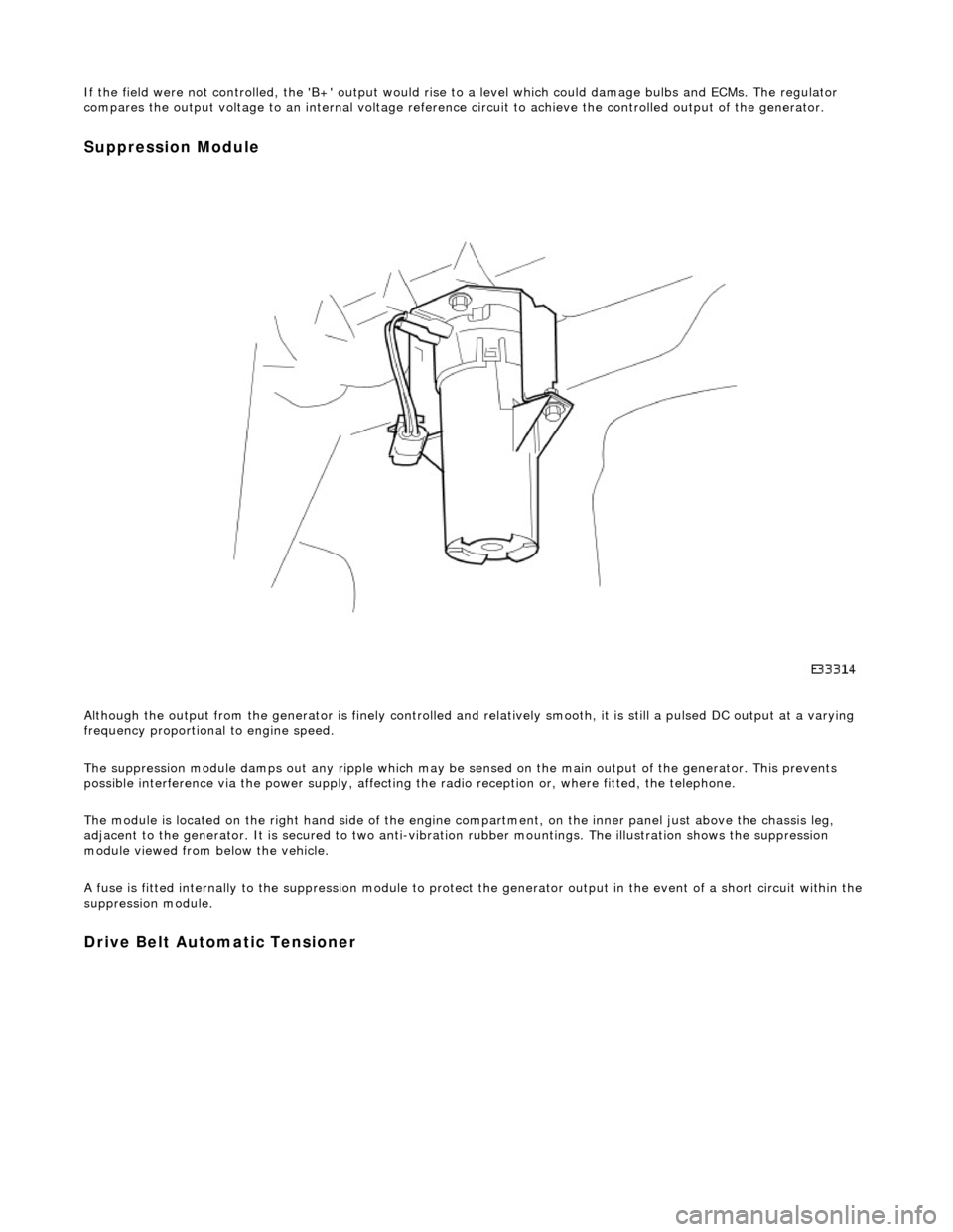
Suppression Module
Although the output from the generator is fi nely controlled and relatively smooth, it is still a pulsed DC output at a varying
frequency proportional to engine speed.
The suppression module damps ou t any ripple which may be sensed on the main output of the generator. This prevents
possible interference via the power supply, affecting the radio reception or, where fitted, the telephone.
The module is located on the right hand side of the engine compartment, on the inner panel just above the chassis leg,
adjacent to the generator. It is secured to two anti-vibration rubber moun tings. The illustration shows the suppression
module viewed from below the vehicle.
A fuse is fitted internally to the suppression module to protect the generator output in the event of a short circuit within th e
suppression module.
Drive Belt Automatic Tensioner
Page 1893 of 2490
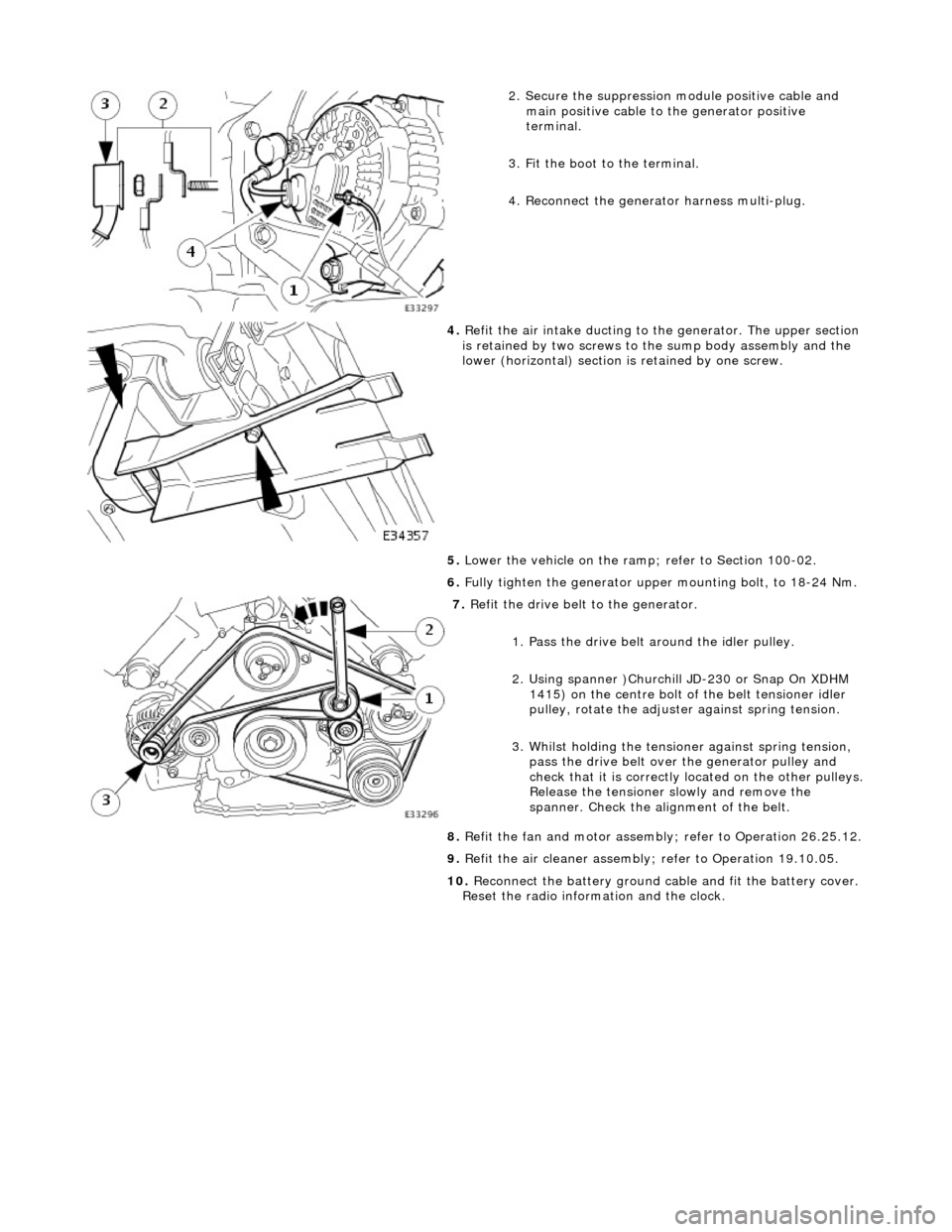
2. Secure the suppression module positive cable and
main positive cable to the generator positive
terminal.
3. Fit the boot to the terminal.
4. Reconnect the generator harness multi-plug.
4. Refit the air intake ducting to the generator. The upper section
is retained by two screws to the sump body assembly and the
lower (horizontal) section is retained by one screw.
5. Lower the vehicle on the ramp ; refer to Section 100-02.
6. Fully tighten the generator upper mounting bolt, to 18-24 Nm.
7. Refit the drive belt to the generator.
1. Pass the drive belt around the idler pulley.
2. Using spanner )Churchill JD-230 or Snap On XDHM 1415) on the centre bolt of the belt tensioner idler
pulley, rotate the adjuster against spring tension.
3. Whilst holding the tensioner against spring tension, pass the drive belt over the generator pulley and
check that it is correctly located on the other pulleys.
Release the tensioner slowly and remove the
spanner. Check the alignment of the belt.
8. Refit the fan and motor assembly ; refer to Operation 26.25.12.
9. Refit the air cleaner assembly; refer to Operation 19.10.05.
10. Reconnect the battery ground cable and fit the battery cover.
Reset the radio inform ation and the clock.