radio JAGUAR X308 1998 2.G Owner's Guide
[x] Cancel search | Manufacturer: JAGUAR, Model Year: 1998, Model line: X308, Model: JAGUAR X308 1998 2.GPages: 2490, PDF Size: 69.81 MB
Page 1898 of 2490
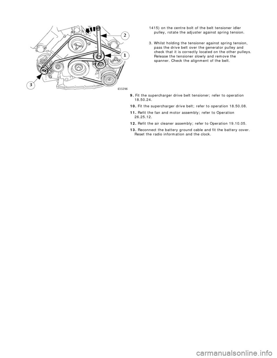
1415) on the centre bolt of the belt tensioner idler
pulley, rotate the adjuster against spring tension.
3. Whilst holding the tensioner against spring tension, pass the drive belt over the generator pulley and
check that it is correctly located on the other pulleys.
Release the tensioner slowly and remove the
spanner. Check the alignment of the belt.
9. Fit the supercharger drive belt tensioner; refer to operation
18.50.24.
10. Fit the supercharger drive belt ; refer to operation 18.50.08.
11. Refit the fan and motor asse mbly; refer to Operation
26.25.12.
12. Refit the air cleaner assembly; refer to Operation 19.10.05.
13. Reconnect the battery ground cable and fit the battery cover.
Reset the radio inform ation and the clock.
Page 1904 of 2490
Audio Unit - Audio System
Description and Operation
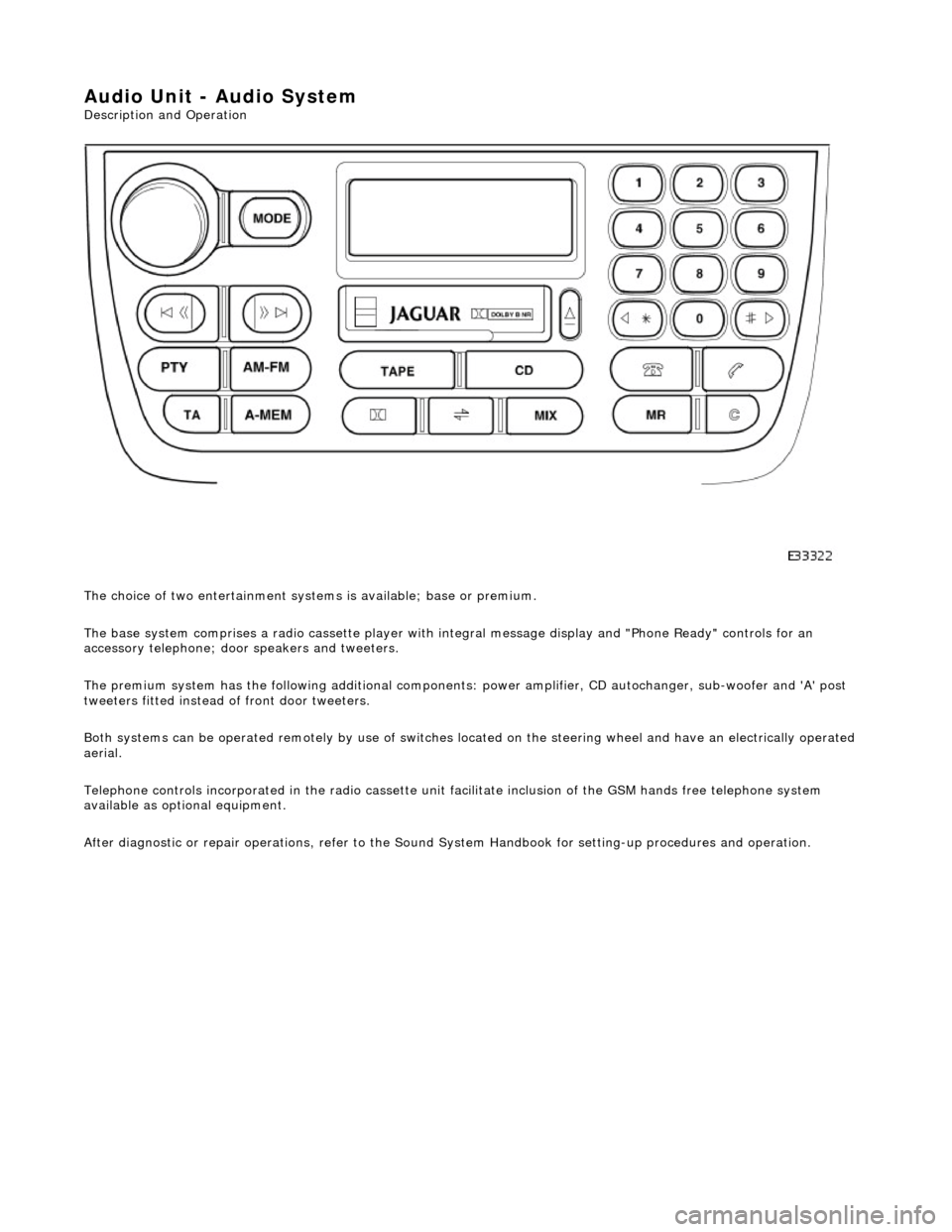
The choice of two entertainment system s is available; base or premium.
The base system comprises a radio cassette player with in tegral message display and "Phone Ready" controls for an
accessory telephone; door speakers and tweeters.
The premium system has the following additional components: power amplifier, CD autochanger, sub-woofer and 'A' post
tweeters fitted instead of front door tweeters.
Both systems can be operated remotely by use of switches loca ted on the steering wheel and have an electrically operated
aerial.
Telephone controls incorporated in the ra dio cassette unit facilitate inclusion of the GSM hands free telephone system
available as optional equipment.
After diagnostic or repair operations, refer to the Sound System Handbook for setting-up procedures and operation.
Page 1906 of 2490
Audio Unit - Audio System
Diagnosis and Testing
Tests Using the Portable Diagnostic Unit
Refer to PDU User Guide
The PDU is unable to diagnose radio head, CD autochanger or amplifier faults; there are no self-diagnostics associated with
these components.
PDU is able to test the speakers and the antenna, along with associated wiring and connections, therefore by a process of
elimination, the other components can be diagnosed.
Page 1907 of 2490
Audio Unit - Capacitor
Removal and Installation
Removal
Installation
1. Disconnect the batt ery ground cable.
Remove the battery cover.
2. Raise the vehicle on a ramp.
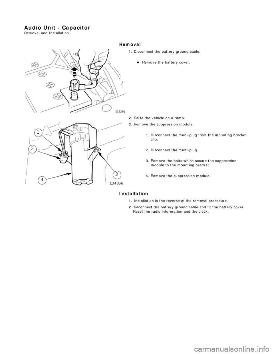
3. Remove the suppr ession module.
1. Disconnect the multi-plug from the mounting bracket clip.
2. Disconnect the multi-plug.
3. Remove the bolts which secure the suppression module to the mounting bracket.
4. Remove the su ppression module.
1. Installation is th e reverse of the re moval procedure.
2. Reconnect the battery ground cable and fit the battery cover.
Reset the radio inform ation and the clock.
Page 1908 of 2490
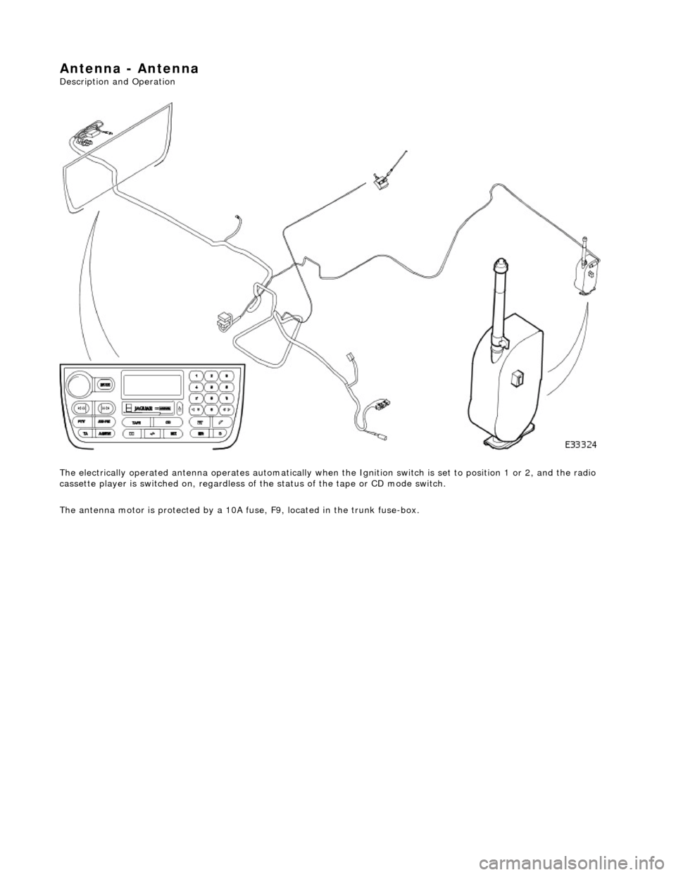
Antenna - Antenna
Description and Operation
The electrically operated antenna operates automatically when the Ignition switch is set to position 1 or 2, and the radio
cassette player is switched on , regardless of the status of the tape or CD mode switch.
The antenna motor is protected by a 10A fuse, F9, located in the trunk fuse-box.
Page 1909 of 2490

Antenna - Antenna
Diagnosis and Testing
Tests Using the Portable Diagnostic Unit
Refer to PDU User Guide
The PDU tests whether or not the antenna raises and lowers correctly. Although it is obvious if the antenna is not operating,
the PDU analyses why it is not operating an d indicates problems such as a faulty radio head signal output, faulty wiring, loss of power due to a blown fuse.
Page 1911 of 2490

Speakers - Speakers
Diagnosis and Testing
Tests Using the Portable Diagnostic Unit
Refer to PDU User Guide
PDU can test for correct operation of each speaker and can provide fault guidance for any that fail to function.
PDU can indicate problems such as a faulty radio head output power signal, faulty power amplifier (where fitted), faulty
wiring, loss of power due to a blown fuse.
Page 1976 of 2490
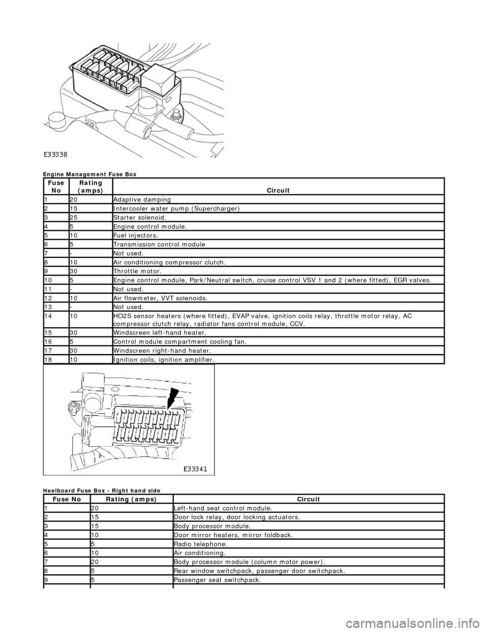
Engine Management Fuse Box
Heelboard Fuse Box - Right hand side
Fuse NoRating
(amps)Circuit
120Adaptive damping
215Intercooler water pump (Supercharger)
325Starter solenoid.
45Engine control module.
510Fuel injectors.
65Transmission control module
7-Not used.
810Air conditioning compressor clutch.
930Throttle motor.
105Engine control module, Park/Neutr al switch, cruise control VSV 1 and 2 (where fitted), EGR valves.
11-Not used.
1210Air flowmeter, VVT solenoids.
13-Not used.
1410HO2S sensor heaters (where fitted ), EVAP valve, ignition coils relay, throttle motor relay, AC
compressor clutch relay, radi ator fans control module, CCV.
1530Windscreen left-hand heater.
165Control module compartment cooling fan.
1730Windscreen right-hand heater.
1810Ignition coils, ignition amplifier.
Fuse NoRating (amps)Circuit
120Left-hand seat control module.
215Door lock relay, door locking actuators.
315Body processor module.
410Door mirror heaters, mirror foldback.
55Radio telephone.
610Air conditioning.
720Body processor module (column motor power).
85Rear window switchpack, passenger door switchpack.
95Passenger seat switchpack.
Page 1977 of 2490
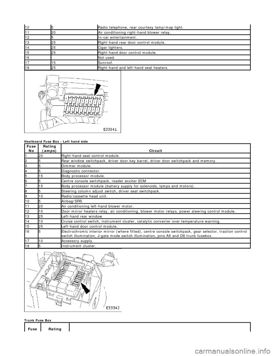
Heelboard Fuse Box - Left hand side
Trunk Fuse Box
105Radio telephone, rear courtesy lamp/map light.
1120Air conditioning right-hand blower relay.
125In-car entertainment.
1325Right-hand rear door control module.
1425Cigar lighters.
1525Right-hand door control module.
16-Not used.
1715Sunroof.
1825Right-hand and left-hand seat heaters.
Fuse NoRating
(amps)Circuit
120Right-hand seat control module.
25Rear window switchpack, driver door key ba rrel, driver door switchpack and memory.
35Dimmer module.
45Diagnostic connector.
515Body processor module.
65Centre console switchpack, reader exciter ECM
715Body processor module (battery supply for solenoids, lamps and motors).
85Steering column adjust switch, driver seat switchpack.
910Radio/cassette head unit.
105Airbag/SRS
1120Air conditioning left-hand blower motor.
1210Door mirror heaters relay, air conditioning, blow er motor relays, power steering control module.
1325Left-hand rear window
1410Cruise control switch, instrument cluster, catalytic converter over temperature warning.
1525Left-hand door control module.
165Electrochromic interior mirror (where fitted), centre console switchpack, gear selector, traction control
switch illumination, J-gate mode switch illumination, pins A9 and D8 trunk fusebox.
1710Accessory supply.
185Instrument cluster.
Fuse Rating
Page 2021 of 2490
Body System - General Information - Body
Description and Operation
This section covers the following areas of the vehicle body:
Front end body panels
Body closures
Aperture seals
Door seals
Instrument panel, console and radio
Centre console
Handles, locks, latches and mechanisms
Wipers and washers
Glass, frames and mechanisms
Fascia
Fuel filler flap assembly
Sun visors
Seating
Interior trim and ornamentation
Exterior trim and ornamentation
Rear view mirrors
Rear parcel tray
Roof console
Bumpers
Occupant restraints
Sliding roof
Steering column cowl
Underscuttle pad
Front End Body Panels
A false bulkhead together with two insulation covers, are installed between the engine compartment and the BIW front
bulkhead to provide optimum insulation ag ainst noise and heat intrusion. Two plenum braces bolted between the BIW upper toeboards and the plenum further increase bodyshell structural integrity. The plastic ra diator grill and vane block achieve
weight reductions over steel parts and provid e high resistance to front end corrosion.