steering JAGUAR X308 1998 2.G Owner's Manual
[x] Cancel search | Manufacturer: JAGUAR, Model Year: 1998, Model line: X308, Model: JAGUAR X308 1998 2.GPages: 2490, PDF Size: 69.81 MB
Page 95 of 2490

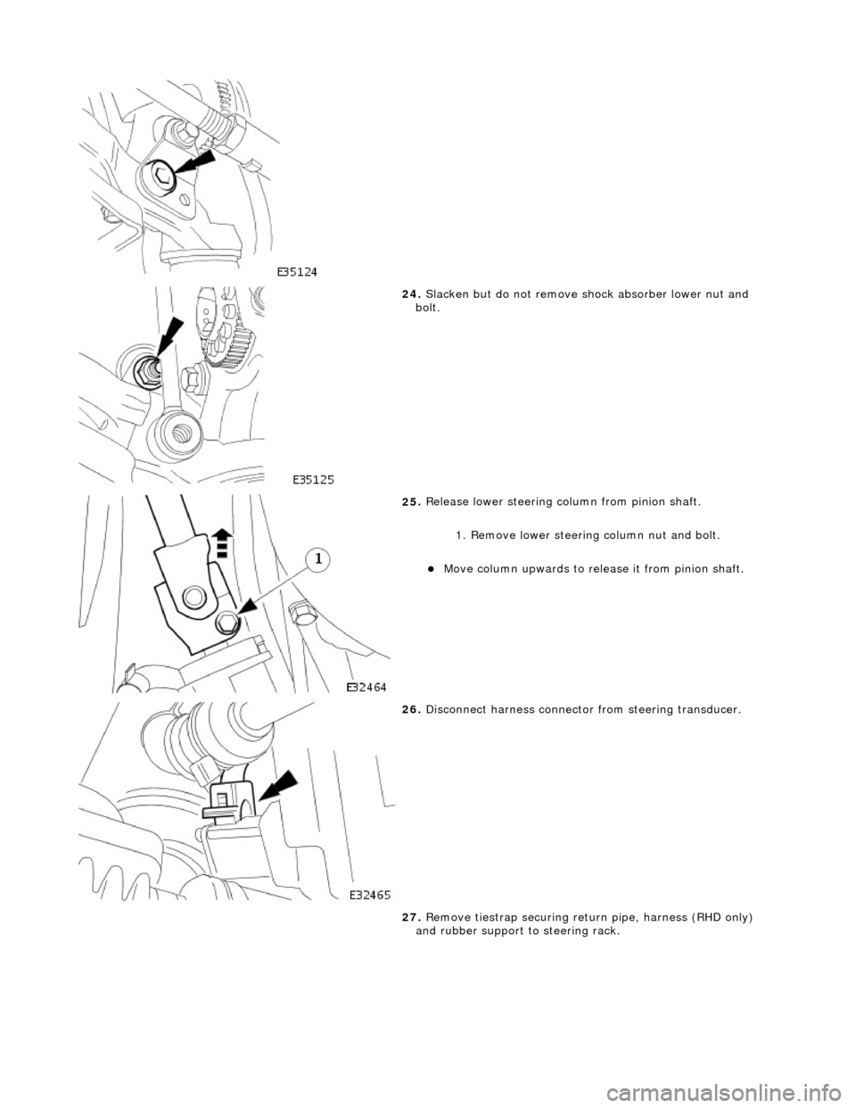
24
.
Slacken but do not remove shock absorber lower nut and
bolt.
25
.
Release lower steering column from pinion shaft.
1. Remove lower steering column nut and bolt.
Move column up
wards to release it from pinion shaft.
26
.
Disconnect harness connector from steering transducer.
27. Remove tiestrap securing retu rn pipe, harness (RHD only)
and rubber support to steering rack.
Page 96 of 2490

28. CAU
TION: Do not allow steerin
g pipes to support weight
of steering rack.
Position steering rack for access.
Pivot steering arm ful
ly downwards
Re
move steering rack securing bolts.
Carefully move steer
ing rack
downwards for access to
wishbone eccentric bolt.
29 . R
emove lower wishbone rear
arm eccentric bolt and nut.
Mark position of eccentri
c bo
lt large graduation mark on
crossbeam.
Remove wish
bone eccent
ric bolt and nut.
30. Remove lower wishbone rear arm/ball joint assembly from
crossbeam.
31 . R
emove lower wishbone front
arm eccentric bolt and nut.
Mark position of eccentri
c bo
lt large graduation mark on
crossbeam.
Re
move wishbone front ec
centric bolt and nut.
32. Remove lower wishbone front arm from crossbeam.
33. NOTE: For assembly purposes, note orientation of bush.
• NOTE: Initial press action will cause tool to sh ear bush flange.
Using a hydraulic press, remove bush from wishbone front arm.
Page 98 of 2490

not ti
ghten eccentric bolt and nut.
4. Install steeri
ng rack on crossbeam.
Ensure that b
ushes are correct
ly positioned on steering
rack.
Posi ti
on steering rack on crossbeam.
Position support brac
kets over bus
hes.
Install mountin
g bracket bolts an
d tighten to 41-54Nm.
5. Inst al
l lower steering column on pinion shaft.
Move col
u
mn downwards to engage coupling splines on
pinion shaft.
1. Install nut and bolt and tighten to 22-28Nm.
6. Position an d
connect harnes
s to steering transducer.
RHD veh
icles. Position steeri
ng harness behind return
pipe.
Conne ct
harness to transducer.
7. Secure return pipe on steering rack.
1. Position pipe rubber support on steering rack.
2. Position pipe on support .
3. RHD vehicles. Position harness on pipe support rubber.
Page 100 of 2490

12. Position verti
cal link/ hub asse
mbly on lower ball joint taper
pin, install nut and tighten to 60-80Nm.
13 . Position verti
cal link/ hub asse
mbly on upper ball joint taper
pin.
14 . Install nu
t securing upper ball jo
int to vertical link and tighten
to 60-80Nm.
15. Position tie rod ball joint taper pin on steering arm and install
and tighten nut to 71-85Nm.
Page 104 of 2490

31
. Ensuri
ng graduation mark remains aligned, finally tighten
wishbone front eccentric bolt to 113-153Nm.
32. Carry out steering geometry an d wheel alignment checks and
if necessary adjust. Refer to 57.65.01.
Page 116 of 2490

Align sp
ring pan with lower wishbone bolt locations.
Rot
ate tool adjuster to gradua
lly increase spring tension.
P
r
ogressively install but do no
t tighten spring pan securing
bolts.
Ti ghten spring pan
securing bolts to 70-90Nm.
Ensure spri
ng
lower rubber seat is correctly positioned in
spring pan.
6. WARNING: WHE N
ROTATING TOOL ADJUSTER, ENSURE
THAT TOOL STEM DOES NOT TU RN AND DISTURB POSITION OF
DOWEL IN SUSPENSION TURRET.
Remove Special Tool 204-111 from suspension.
Rotat
e adjuster of Special Tool to release tension on
spring.
R otate
tool stem to release dowel from turret.
With
draw tool and adaptor
.assembly.
7.
Lower vehi cle to work
ing heig
ht and support on stands.
8. Install road wheel. Re fer to Section 100-02.
9. Raise vehicle, remove stands and lower vehicle onto road
wheels.
10. Carry out steering geometry an d wheel alignment checks and
if necessary adjust. Refer to 57.65.01.
11. Carry out steering geometry an d wheel alignment checks and
if necessary adjust. Refer to 57.65.01.
Page 130 of 2490

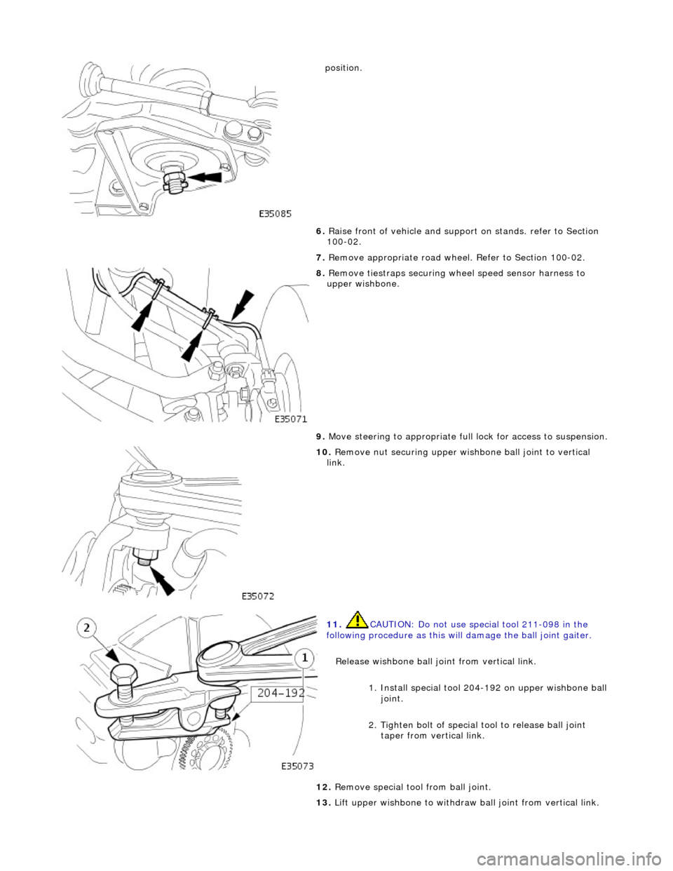
positio
n.
6. Raise front of vehicle and support on stands. refer to Section
100-02.
7. Remove appropriate road wheel. Refer to Section 100-02.
8. Remove t
iestraps securing wheel speed sensor harness to
upper wishbone.
9. Move steering to appropriate full lock for access to suspension.
10. R
emove nut securing upper wish
bone ball joint to vertical
link.
11 . CAUTI
ON: Do not use special tool 211-098 in the
following procedure as this will damage the ball joint gaiter.
Release wishbone ball joint from vertical link.
1. Install special tool 204-192 on upper wishbone ball joint.
2. Tighten bolt of special tool to release ball joint
taper from vertical link.
12 . Re
move special tool from ball joint.
13. Lift upper wishbone to withdraw ball joint from vertical link.
Page 134 of 2490

17.
R
elease dowel of special tool 204-114 from suspension turret
slot.
18. Raise vehicle for access an d remove special tool from
suspension.
19. Fully lower vehicle.
20. Carry out steering geometry an d wheel alignment checks and
if necessary adjust. Refer to 57.65.01.
Page 140 of 2490

slots.
Install rotor nut spring-clip.
Inst al
l spring clip in hub retaining holes and castellated
slots of the rotor nut.
9. Inst al
l disc shield.
1. Position disc shield on vertical link.
2. Install bolts.
10. Install vertical link and hub as sembly on vehicle. Refer to
60.25.38.90.
11. Carry out steering geometry an d wheel alignment checks and
if necessary adjust. Refer to 57.65.01.
Page 146 of 2490

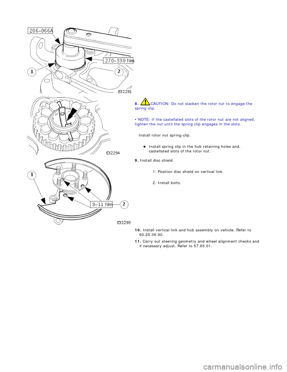
8.
CAUTIO
N: Do not slacken the rotor nut to engage the
spring clip.
• NOTE: If the castellated slots of the rotor nut are not aligned,
tighten the nut until the spring clip engages in the slots.
Install rotor nut spring-clip.
Inst
all spring clip in the hub retaining holes and,
castellated slots of the rotor nut.
9. Inst al
l disc shield.
1. Position disc shield on vertical link.
2. Install bolts.
10. Install vertical link and hub as sembly on vehicle. Refer to
60.25.38.90.
11. Carry out steering geometry an d wheel alignment checks and
if necessary adjust. Refer to 57.65.01.