valve JAGUAR X308 1998 2.G Owner's Manual
[x] Cancel search | Manufacturer: JAGUAR, Model Year: 1998, Model line: X308, Model: JAGUAR X308 1998 2.GPages: 2490, PDF Size: 69.81 MB
Page 436 of 2490
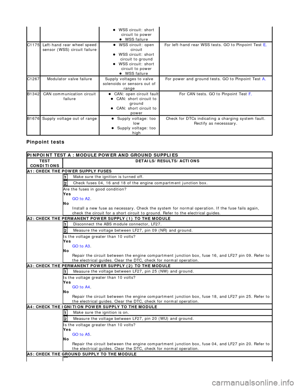
Pinpoint tests
W
S
S circuit: short
circuit to power
WSS f
ailure
C1
175Left -hand re
ar wheel speed
sensor (WSS) circuit failure
W S
S circuit: open
circuit
WS
S circuit: short
circuit to ground
W S
S circuit: short
circuit to power
WSS f
ailure
F
or l
eft-hand rear WSS test
s. GO to Pinpoint Test E.
C1267Modulat or valv
e failure
Supply volt
ages
to valve
solenoids or sensors out of range
Fo
r power and ground tests. GO to Pinpoint Test
A.
B1342CAN co
mmunication circuit
failure
CAN :
open circuit fault
CAN:
short circuit to
ground
CAN :
short circuit to
power
Fo
r CAN tests. GO to Pinpoint Test
F.
B1676Supply volt
age out of range
Supply voltage:
too
low
Supply volt age:
too
high
Check fo
r DTCs indicating a charging system fault.
Rectify as necesssary.
PI
NPOINT TEST A : MODULE
POWER AND GROUND SUPPLIES
TES
T
CONDITIONS
D E
TAILS/RESULTS/ACTIONS
A
1
: CHECK THE POWER SUPPLY FUSES
Make sure the igniti
on is turned off. 1
Chec
k fuses 04, 16 and 18 of the engine compartment junction box.
2
Are th
e fus
es in good condition?
Yes GO to A2
.
No
Install a new f
use as
necessary. Check the syst em for normal operation. If the fuse fails again,
check the circuit for a short circuit to ground. Refer to the electrical guides.
A2: CHECK THE PERMANENT
POWER SUPPLY (1) TO THE MODULE
Disc
onnect the ABS module connector, LF27.
1
Measure the voltage between LF
2
7, pin 09 (NR) and ground.
2
Is the vol
t
age greater than 10 volts?
Yes GO to A3
.
No Re
pair the circuit between the engine compartment
junction box, fuse 16, and LF27 pin 09. Refer to
the electrical guides. Clear the DTC, check for normal operation.
A3: CHECK THE PERMANENT
POWER SUPPLY (2) TO THE MODULE
Meas
ure t
he voltage between LF27, pin 25 (NW) and ground.
1
Is the vol
t
age greater than 10 volts?
Yes GO to A4
.
No
Re
pair the circuit between the engine compartment ju
nction box, fuse 18, and LF27 pin 25. Refer to
the electrical guides. Clear the DTC, check for normal operation.
A4: CHECK
THE IGNITION POWER SUPPLY TO THE MODULE
Make sure the ignition is on. 1
Measure the
voltage between LF 2
7, pin 20 (WU) and ground.
2
Is the vol
t
age greater than 10 volts?
Yes GO to A5
.
No Re
pair the circuit between the engine compartment ju
nction box, fuse 04, and LF27 pin 20. Refer to
the electrical guides. Clear the DTC, check for normal operation.
A5: CHECK
THE GROUND SUPPLY TO THE MODULE
Page 458 of 2490
The
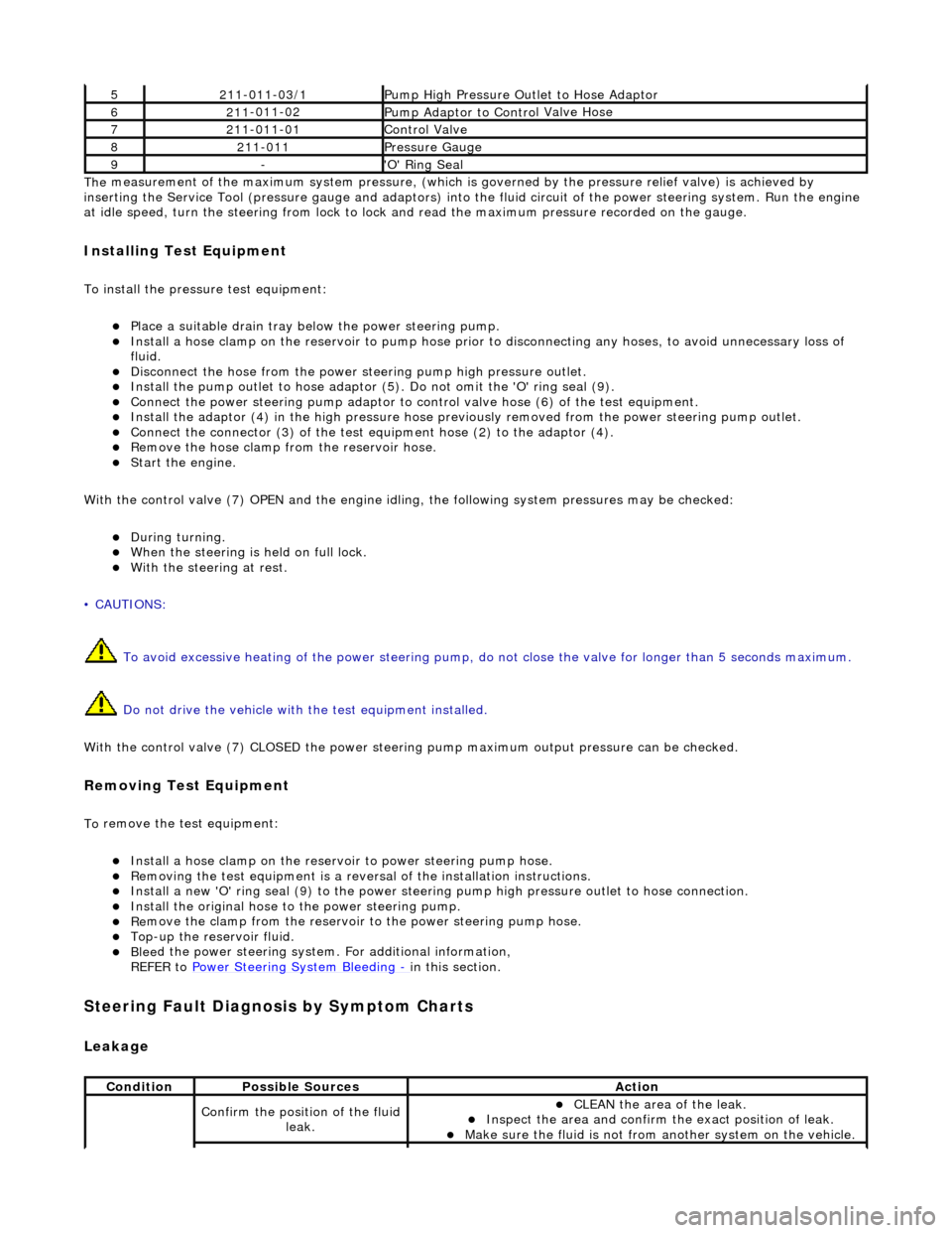
measurement of the maximum system pressure, (which is
governed by the pressure relief valve) is achieved by
inserting the Service Tool (pressure gauge and adaptors) into th e fluid circuit of the power steering system. Run the engine
at idle speed, turn the st eering from lock to lock and read the ma ximum pressure recorded on the gauge.
Installin
g Test Equipment
To
in
stall the pressure test equipment:
Pla
c
e a suitable drain tray be
low the power steering pump.
Install a hose clamp on
the re
servoir to pump hose prior to disconnecting any hoses, to avoid unnecessary loss of
fluid.
Disc
onnect the hose from the power st
eering pump high pressure outlet.
Install the pu
mp outlet to hose adaptor (5
). Do not omit the 'O' ring seal (9).
Connect the power steering
pump
adaptor to control valve hose (6) of the test equipment.
Install th e adaptor (4) in th
e high
pressure hose previously removed from the power steering pump outlet.
Conn
ect the connector (3) of the test equipment hose (2) to the adaptor (4).
R
e
move the hose clamp fro
m the reservoir hose.
Start th
e engine.
With the control valve (7) OPEN and the engine idli ng, the following system pressures may be checked:
Du
ring turning.
W
h
en the steering is
held on full lock.
With
the steeri
ng at rest.
• CAUTIONS:
To avoid excessive heating of the po wer steering pump, do not close the valve for longer than 5 seconds maximum.
Do not drive the vehicle with the test equipment installed.
With the control valve (7) CLOSED the power steering pump maximum ou tput pressure can be checked.
Removing Test Equipment
To
remove the test equipment:
Install a hose clamp
on
the reservoir to power steering pump hose.
Re
movi
ng the test equipmen
t is a reversal of the in stallation instructions.
Install a new '
O
' ring seal (9) to the power steering pump high pressu
re outlet to hose connection.
Instal
l the original hose to
the power steering pump.
Re
move the clamp from the reservoir to
the power steering pump hose.
Top-up the reservoir flui
d.
Ble
e
d the power steerin
g system. For additional information,
REFER to Power Steering System Bleeding
- in thi
s section.
Stee
ring Fault Diagnosis by Sympt
om Charts
Leakage
52
11-0
11-03/1
Pump High Pressure Ou
tlet
to Hose Adaptor
621
1
-011-02
Pump Adaptor
to Contro
l Valve Hose
721
1
-011-01
Control Valve
82
11-
011
Pressure Gauge
9-'O
'
Ring Seal
Cond
iti
on
Possib
l
e Sources
Acti
o
n
Co
nfirm
the position of the fluid
leak.
CLEAN th
e area of the leak.
In
s
pect the area and confirm the exact position of leak.
Make sure the fluid
is not from anoth
er system on
the vehicle.
Page 463 of 2490
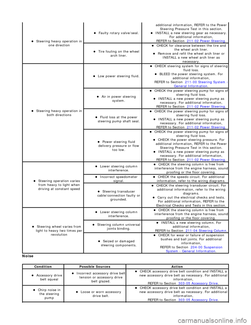
No
ise
S
teering heavy operation in
one direction
F
aulty rotary valve/seal.
addi
tional information, REFER to the Power
Steering Pressure Test in this section.
INST
ALL a new steering
gear as necessary.
For additional information,
REFER to Section 211
-0
2 Power Steering
.
Ti
re fouling on the wheel
arch liner.
CHECK for
clearance be
tween the tire and
the wheel arch liner.
R
emove and refit the wheel arch liner or
INSTALL a new wheel arch liner as necessary.
S
teering heavy operation in
both directions
Low power steer
ing fluid.
CHE
CK steering system
for signs of steering
fluid loss.
BLEE
D the power steering system. For
additional information,
REFER to Section 211
-0
0 Steering System
- General Informati
on
.
Ai
r in power steering
system.
CHECK
the power steering pump for signs o
f steering fl
uid loss.
INST
ALL a new power steering pump as
necessary. For additi onal information,
REFER to Section 211
-0
2 Power Steering
.
Fluid loss at the power
steering pump shaft seal.
CHECK
the power steering pump for signs o
f steering fl
uid loss.
INST
ALL a new power steering pump as
necessary. For additi onal information,
REFER to Section 211
-0
2 Power Steering
.
Power steeri
ng fluid
delivery pressure or flow too low.
CHECK
the power steering pump for signs o
f steering fl
uid loss.
CHECK
the power stee
ring pressure. For
additional information, REFER to the Power Steering Pressure Test in this section.
INST
ALL a new power steering pump as
necessary. For additi onal information,
REFER to Section 211
-0
2 Power Steering
.
Steeri
ng operation varies
from heavy to light when
driving at constant speed
Lower steeri
ng column
interference.
CHECK
the steering co
lumn is free from
interference from the en gine harness, sound
proofing or the floor covering.
Incorre
ct sp
eedometer
signal.
CHECK
the speedo circ
uit. For additional
information, refer to the wiring diagrams.
Steeri
ng transducer
cable/connection faulty or grounded.
CHECK
the steering transducer circuit. For
additional information, refer to the wiring diagrams.
Carry ou
t the electrical checks and tests.
For additional information, REFER to the
Electrical Checks and Tests in this section.
Steeri
ng wheel varies from
light to heavy two times per revolution
Lower steeri
ng column
interference.
CHECK
the steering co
lumn is free from
interference from the en gine harness, sound
proofing or the floor covering.
Steeri
ng column universal
joints binding.
IN
STALL a new steering column. For
additional information,
REFER to Section 211
-0
4 Steering Column
.
Seized or damaged
ste
ering components.
CHECK
for wear or failure of suspension
bushes and ball join ts. For additional
information,
REFER to Section 204
-00
Suspension
Sy
stem
- General
Information
.
Cond
ition
Possib
le Sources
Acti
on
Acce
ssory drive
belt squeal
Incorre
ct accessory drive belt
tension or accessory drive belt glazed.
CHECK
accessory drive belt condition and INSTALL a
new accessory drive belt as necessary. For additional
information,
REFER to Section 303
-0
5 Accessory Drive
.
Chir
p noise in
the steering pump
Loose or worn accessory dr
ive belt.
CHECK
accessory drive belt condition and INSTALL a
new accessory drive belt as necessary. For additional
information,
REFER to Section 303
-0
5 Accessory Drive
.
Page 466 of 2490
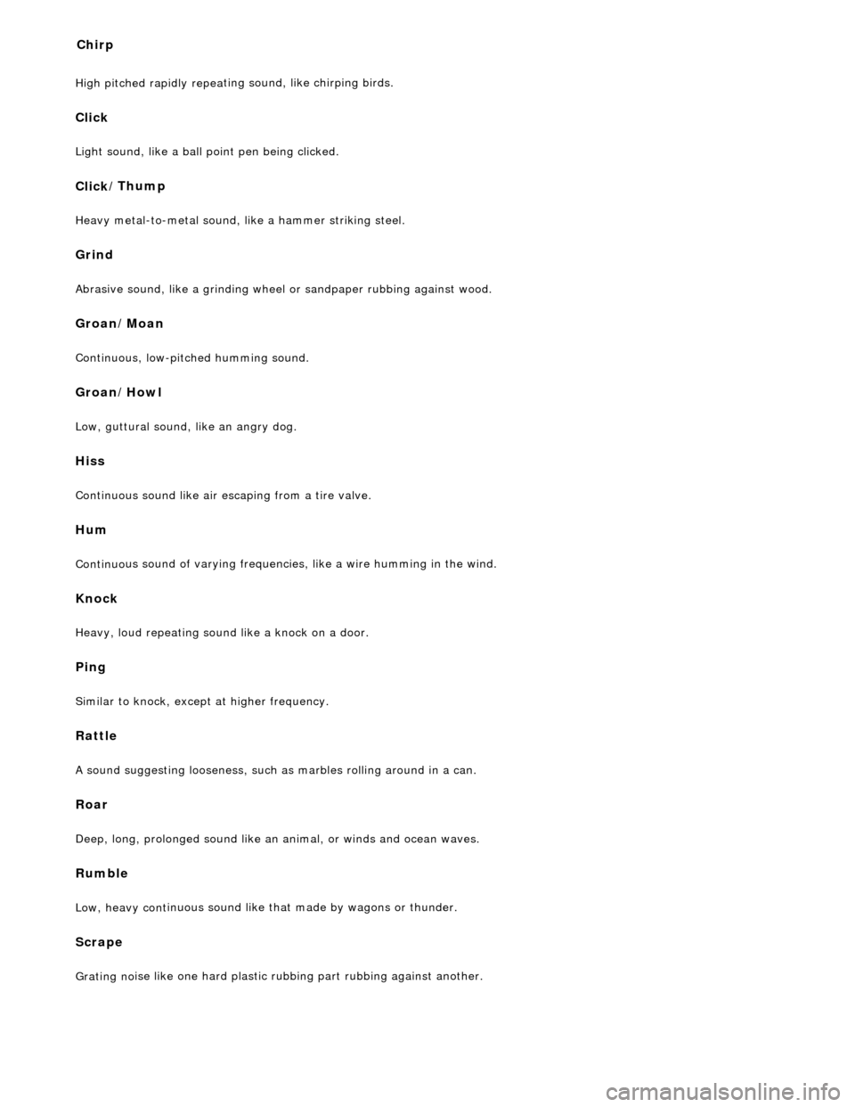
High pitched rapidly repea
ting sound, like chirping birds.
Cli
c
k
Ligh
t sou
nd, like a ball point pen being clicked.
Click
/
Thump
Heav
y
metal-to-metal sound, li
ke a hammer striking steel.
Grin
d
Abrasiv
e
sound, like a grinding wheel or sandpaper rubbing against wood.
Gr
oan
/Moan
Continu
o
us, low-pitched humming sound.
Groan
/Howl
Low, guttural sound, like an an
gry do
g.
Hiss
Continuous sound
like air escaping from a tire valve.
Hum
Continu o
us sound of varying frequencie
s, like a wire humming in the wind.
Knock
Heavy, loud repeat
ing sound like a knock on a door.
Pi
n
g
Si
mi
lar to knock, except at higher frequency.
Ratt
le
A s
ound suggesting looseness, such as marbles rolling around in a can.
Roar
Deep, long, prolonged sou
nd like an
animal, or winds and ocean waves.
Rumble
Low, he
avy cont
inuous sound like that made by wagons or thunder.
Scrape
Grating no
ise l
ike one hard plastic ru
bbing part rubbing against another.
Chir
p
Page 468 of 2490
Hiss (Swish)
Hiss or Val
ve Hiss is a high-frequency so
und coming from the steering gear when the system is loaded. It is a rushing or
"swish" noise that doesn't change frequency with RPM. Hiss is the general noise generated by the flow of hydraulic fluid
through restrictions in the steer ing system. Restrictions include the rotary stee ring valve, power steering tubes, connectors,
tuning orifices, etc. Hiss can be air- borne and structure-borne, but the structure-borne path through the steering
intermediate shaft is usually dominant.
Moan (Groan)
Moan is the general structu r
e-borne noise of the steering system. Moan is primarily transmitted to the driver via the body
structure through the pump mount, engine mounts, power steering lines and power steering brackets. On some vehicles,
moan is a load humming noise, often present when the wheel is turned and the system is loaded. It may change frequency
with engine RPM and if the sy stem is loaded or unloaded.
Rack Knock (R
ack Slap)
CAU
T
ION: DO NOT attempt to adjust the stee
ring gear yoke. Failure to follow this instruction will result in the steering
gear warranty to become invalid.
Rack Knock is a rattle sound an d steering wheel vibration caused by separation of the steering gear and pinion while driving
over bumps. It is a structure-borne noise transmitted throug h the intermediate shaft and column. Rack knock can also be
heard as a "thump" or impact noise that occurs with the vehicle stationary when the steering wheel is released from a
loaded position and allowed to return to rest . Noise occurs with the engine on or off.
Rattles
Ra
ttles are noises caused by knocking or hitting with components in the steering system. Steering rattles can occur in the
engine compartment, the suspension, or the passenger compartment . Rattles can be caused by loose parts, movable and
flexible parts, and improper clearances.
Squea k
s/Scrapes
Squeaks/Scrapes are noises due
to fri
ction or component rubbi
ng anywhere in the steering system. Squeaks/Scrapes have
appeared in steering linkages and jo ints, in column components and in co lumn and steering wheel trim parts.
Weep
We
ep is an air-borne noise, occasionally
generated when turning the steering across lock at a constant rate. When present
on a vehicle the noise, once initiated can often be maintained across a large proportion of the available steering movement.
Whistle
Wh
istle is similar to hiss but is louder and of a higher frequency. It is also more
of a pure tone noise than hiss. Whistle is
air-borne and is generated by a high flow rate of hydraulic fluid through a small restriction.
Zip
Zip n
o
ise is the air-borne noise
generated by power steerin g pump cavitation when power steering fluid does not flow freely
through the suction hose from the rese rvoir to the pump. Zip primarily occurs during cold weather at start-up.
Steering System Vibrations and Harshne
ss
Buzz
Buzz is a tactile rotary vi
bration felt in
the steering wheel for slow steering inputs. Buzz can also be called a grinding feel
and it is closely related to grunt and is caused by high system gain with low damping. Buzz is generally excited during
parking manoeuvres with low to medium speed steering input.
Page 478 of 2490
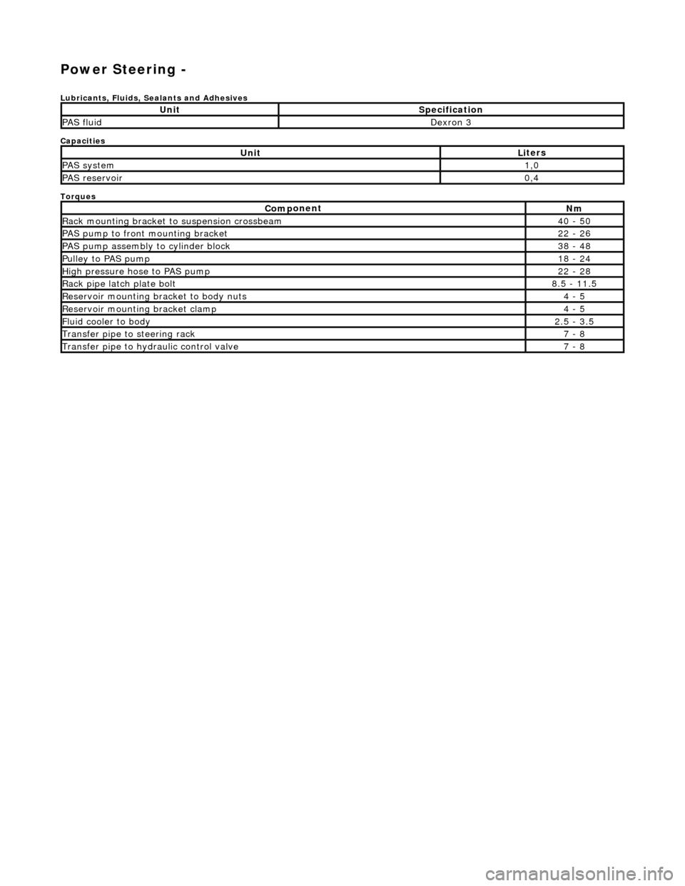
Power Steering -
Lubric
ants, Fluids, Sealants and Adhesives
Capacities
Torques
UnitSp
ecification
PAS flu
i
d
De
xr
on 3
UnitLi
t
ers
PAS syste
m1,0
PAS reservoi
r0,4
Com p
onent
Nm
Rac
k
mountin
g brac
ke
t to suspension crossbeam
40
- 50
PAS pump to front mounti
ng bracket
22
-
26
P
AS pu
mp assembly to cylinder block
38
-
48
Pul
l
ey to PAS pump
18
-
24
Hi
gh pressure hose to PAS pump22 -
28
Rack
pipe latch plate bolt8.5 -
11.5
R
e
servoir mounting bracket to body nuts
4 -
5
R
e
servoir mounting bracket clamp
4 -
5
Fluid cooler to body2.
5 -
3.5
Transfer pipe
to steering rack7 -
8
Transfer pipe
to hydraulic con
trol valve
7 -
8
Page 479 of 2490
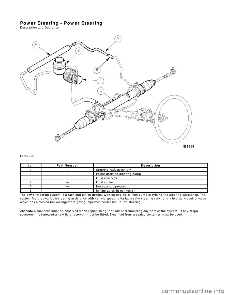
Power Steering - Power Steering
Description an
d Operation
Parts List
The power steering system is a rack and pinion design, with an engine-dri ve n pump providing the steering assistance. The
system features variable steering assistance with vehicle spee d, a variable ratio steering rack, and a hydraulic control valve
which has a torsion bar arrangement giving improved center feel to the steering.
Absolute cleanliness must be observed wh en replenishing the fluid or dismantling any part of the system. If any major
component is renewed a new fluid rese rvoir must be fitted. New fluid from a sealed container must be used.
It
em
Par
t Number
De
scription
1—Steeri
ng rack assembly
2—Power as
sisted steering pump
3—F
luid reservoir
4—F
luid cooler
5—Hoses and pipework
6—In-
line quick-fit connector
Page 480 of 2490

The steering rack assembly :
Is mounted on the
rear face of the
front suspension crossbeam by two forg ed mounting brackets with resilient
bushes. The bushes are handed (pinion side and non-pinion side) and are orientated according to the vehicle range
application.
Convert s
the rotary motion of the steering wheel, via the steering gear pinion, to the lateral motion of the rack.
F
e
atures a variable ratio steering
rack with integral hydraulic po wer steering cylinder and piston.
Has a hydrauli
c control valve with Servotronic co
ntrol and positive center feel torsion bar.
The basic steering rack assembly is not serviceable. The following components are serviceable items:
Transfer pipework
.
Servotronic valve. Cent
ralizing cap.
O
u
ter ball joint.
Rac
k
gaiter.
Clips and
fittings.
Steering Rack Components
It e
m
Par
t
Number
De
scr
iption
1—Front
su
spension crossbeam
2—Steeri
ng rack housi
ng
3—Hydraulic
control valve housing
4—Moun
ting bracke
t
5—Gait
er
6—Tie
rod
7—O
u
ter ball joint
Steering R
a
ck Assembly
Page 481 of 2490

P
arts List
It
em
Par
t Number
De
scription
1—Steeri
ng rack
2—Hydrau
lic control valve
3—Torsio
n bar
4—Pin
ion
5—O
perating cylinder and piston
6—Inne
r ball joint
7—Tie
rod
Page 483 of 2490

P
arts List
The positive center-feel torsion bar improves the straight ahead feel of the steering in the region where very small amounts
of hydraulic pressure, and hence re action pressure, are generated.
The torsion bar assembly forms part of the hydraulic control valve assembly , and includes an axially pre-loaded metal
bellows spring, which is arranged co-axially with the torsion bar. The torsion bar is positively connected between the end
piece and the input shaft. One end of the bellows spring is attached to the input shaft, while the other end is attached to a
centering device. The centering device has two prism-shaped recesses with ca ged, guided, ball bearings arranged between
the recesses, and determines the zero-torsion position of the bellows spring.
On turning the steering wheel from the straight ahead position, the spring fo rces of the torsion bar assembly must be
overcome. Initially, the bellows spring produces substantial additional torsional resistance. However, after an angular
movement of approximately 0.2 degrees the torsional rigidity decreases and becomes similar to a conventional torsion bar.
It
em
Par
t Number
De
scription
1—End piece
2—Torsio
n bar
3—Caged ball bearing
s
4—Centering device
5—Bel
lows spring
6—In
put shaft
Positive Center-Feel Torsion Bar
Torsio
n Bar Components