valve JAGUAR X308 1998 2.G User Guide
[x] Cancel search | Manufacturer: JAGUAR, Model Year: 1998, Model line: X308, Model: JAGUAR X308 1998 2.GPages: 2490, PDF Size: 69.81 MB
Page 70 of 2490
Upper
Wishbones
Each
upper wi
shbone assembly is a on
e-piece steel forging incorporating:
A pres
s-fit ball joint.
Press-fi
t bushes for location of the upper fulcrum bolt.
Lower Wishbones
Each l
o
wer wishbone comprising
forged steel front and rear arms bolted together, incorporates:
A p
ress-fit ball joint in the outer extremity of the rear arm.
Press-f
i
t bushes for location of the lower fulcrum bolts
Locati
on for the shock absor
b
er lower mounting plates.
Vertica l Links
The vertical
links are of forged steel
wi
th integral steering arms. Each is suppo rted between the upper and lower wishbones
by two ball joints and carries:
Front hub
Brake ca
liper and disc shield assembly
ABS se
nsor
.
Front Hub
s
Each f
o
rged steel front hub accommodates sealed for life cartridge
type wheel bearings, and carries:
The brake rotor assembl
y.
A
h
ub nut with toothed, integral ABS rotor.
Su
s
pension spring pi
n locking device.
Front Road
Springs
The road spri
ng
s are of coil type with their
rating dependent upon vehicle specification
Ea
ch spring is installed between the suspension crossbeam location and the lower wishbone spring pan.
Ru
bber seats ar
e installed betw
een the spring and the crossb eam and the spring pan.
Front Shock A
bsorbers
Th
e
shock absorbers are telescopic hydrau
lically operated units. Optional adaptive damping units incorporate a solenoid-
operated control valve at their upper extremity.
Each shoc
k absorber is installed between the lowe
r wishbone rear arm and a recess in the body.
The l
o
wer end of the shock absorber is se
cured to plates on the wishbone by a bolt that also serves as a pivot.
The u
pper en
d of each shock absorber is secured to the body location by a single nut.
Front Sta
b
ilizer Bar
A
front stabil
izer bar installed on all vehicles
is rated according to suspension specification.
Opera
tion
As each road wheel r
i
ses, move
ment is transmitted through the vertical link assembly to the lower wishbone. The resulting
rise of the wishbone compresses the road spring and partially telescopes the shock absorber. During this action, the spring
absorbs associated shocks and the shock absorber minimizes sprin
g os c
illation.
Du
ring cornering, vehicle weight
is transferred to the outer road wheel with a resulting tendency for the inner wheel to lift.
The stabilizer bar assists in minimizing this tendency by transf erring a proportion of potential lift of the inner wheel to the
outer wheel. This result s in enhanced body stability with improved corner ing capabilities.
Page 315 of 2490
Are th
ere any external brake system leaks?
Yes REPAIR as necessary. ADD fluid and BLEED the brak e system. For additional information, refer to
General Procedures in this section. TEST the system for normal operation.
No GO to F3
.
F
3: CARRY OUT A BRAKE MASTER CYLINDER BYPASS TEST
Te
st for brake master cylinder bypass condition. Re
fer to Brake Master Cylinder Component Test in
this section.
1
A
re any concerns found?
Yes INSTALL a new brake master cylinder, ADD flui d and BLEED the brake system. For additional
information, refer to General Proc edures in this section. TEST the system for normal operation.
No System is OK.
PINPO
INT TEST G : EXCESSIVE BRAKE PEDAL EFFORT
TE
ST
CONDITIONS
D
ETAILS/RESULTS/ACTIONS
G1
: CHECK BRAKE PADS
Check the brake pads for wear, contamin
atio
n, correct installation, damage and type.
1
A
re any concerns found?
Yes INSTALL the front brake pads correctly or INSTALL ne w front brake pads if necessary. For additional
information, refer toSection 206
-03
Front Disc Brake
. INSTALL the
rear brake pads correctly or
INSTALL new rear brake pads if necessary. For additional information, refer toSection 206
-04
Rear
Di
sc Brake
. REPEAT road test.
No
GO to G2
.
G2:
CHECK VACUUM
Di
sconnect the vacuum booster hose from the booster.
1
Conne
ct a vacuum/pressure tester to the vacuum hose.
2
Ru
n the engine at normal operating temperature.
3
Re
cord the vacuum reading.
4
Is
the reading 40.5kPa (1
2 in-Hg) or greater?
Yes GO to G3
.
No
LOCATE and REPAIR the source of low vacuum . TEST the system for normal operation.
G3
: INSPECT SYSTEM
Swi
tch the engine off.
1
Re
connect the vacuum hose.
2
Inspect th
e brake booster, rubber grommet, and al
l vacuum plumbing for cracks, holes, damaged
connections, or missing clamps.
3
Pump th
e brake pedal several time
s to exhaust the vacuum. Push down on the brake pedal and hold.
4
Does th
e brake pedal move down
when the engine is started?
Yes Vacuum system is OK.
No GO to G4
.
G4
: CHECK POWER BRAKE BOOSTER VALVE
Check the brake booster valve. For
add
itional information, refer to
Brake Booster in this section.
1
Is th
e power brake booster valve OK?
Yes CHECK the brake booster. Fo r additional information, refer to Brak e Booster in this section. INSTALL a
new brake booster if necessary. TEST the system for normal operation.
No INSTALL a new brake booster valve. TEST the system for normal operation.
P
INPOINT TEST H : BRAKE LOCKUP
DURING LIGHT BRAKE PEDAL FORCE
TE
ST
CONDITIONS
D
ETAILS/RESULTS/ACTIONS
H1
: TEST BRAKE LOCKUP
Page 318 of 2490
Comp
onent Tests
Bra
k
e Booster
1.
1. Chec k all
hoses and connections. All unused vacuum connectors should be capped. Hoses and their connections
should be correctly secured and in good condition with no holes and no collapsed areas. Inspect the valve on the
brake booster for damage.
2. 2. Check the hydraulic brake system for leaks or low fluid.
3. 3. With the transmission in PARK, stop the engine and apply the parking brake. Pump the brake pedal several times
to exhaust all vacuum in the system.
4. 4. With the engine switched off and all vacuum in the system exhausted, appl y the brake pedal and hold it down.
Start the engine. If the vacuum system is operating, the brake pedal will tend to move downward under constant
foot pressure. If no motion is felt, the vacuum booster system is not functioning.
5. 5. Remove the vacuum hose from the brake booster. Manifold vacuum should be available at the brake booster end
of the hose with the engine at idle speed and the transm ission in PARK or NEUTRAL. Make sure that all unused
vacuum outlets are correctly capped, hose connectors are correctly secured and vacuum hoses are in good
condition. When it is established that manifold vacuum is available to the brake booster, connect the vacuum hose
to the brake booster and repeat Step 3. If no downward movement of the brake pedal is felt, install a new brake
booster.
6. 6. Operate the engine for a minimum of 10 seconds at a fast idle. Stop the engine and allow the vehicle to stand for
10 minutes. Then, apply th e brake pedal with approximately 89 N ( 20lb) of force. The pedal feel (brake
application) should be the same as that noted with the engine running. If the brake pedal feels hard (no power
assist), install a new valve and then re peat the test. If the brake pedal still feels hard, in stall a new brake booster.
If the brake pedal movement feels spongy, bleed the brak e system. For additional information, refer to General
Procedures in this section.
Bra k
e Master Cylinder
Usual
l
y, the first and strongest
indicator of anything wrong in the brake syst em is a feeling through the brake pedal. In
diagnosing the condition of the brake master cylinder, check pedal feel as evidence of a brake concern. Check for brake
warning lamp illumination and the brake fluid le vel in the brake master cylinder reservoir.
Normal Conditio
ns
The fo
llowing conditions are considered norm
al and are not indications that the brake master cylinder is in need of repair.
New bra
ke systems are designed to produc
e a pedal effort that is not as hard as in the past. Complaints of light
pedal efforts should be compared to the pedal effort s of another vehicle of the same model and year.
The fl
uid level will fall with brake pad wear.
Abnormal Conditions
•
NOTE: Prior to carrying out any diag
nosis, make sure the brake system warning indicator is functional.
Changes in the brake pedal feel or brake pedal travel are in dicators that something could be wrong in the brake system. The
diagnostic procedure and techniques use brake pedal feel, warning indicator illu mination and low brake fluid level as
indicators to diagnosing brake system co ncerns. The following conditions are cons idered abnormal and indicate that the
brake master cylinder is in need of repair:
Brake ped a
l goes down fast. Th
is could be caused by an ex ternal or internal leak.
Brake pedal goes down slowly
. This could be
caused by an internal or external leak.
Brak
e pedal is low or feels spongy. This condition may be ca
used by no fluid in the brake master cylinder, reservoir
Page 319 of 2490
cap ven
t holes clogged or air in the hydraulic system.
Brake ped
al effort is excessive. This ma
y be caused by a bind or obstruction in the pedal/linkage, a faulty non return
valve, booster or insuffi cient booster vacuum.
R
ear brakes lock up during light pedal force. This may
be caused by damaged brake pads, an incorrectly adjusted
parking brake, a partially applied parking brake, a damaged ABS sensor or bearing failure.
Brake ped
al effort erratic. This condition could be caused by the brake booste
r or incorrectly installed brake pads.
Brake warning indicator i
s on. This may be caused
by low fluid level or float assembly damaged.
No
n Pressure Leaks
Any reduced fluid v
olume in the brake ma
ster cylinder reservoir condition may be caused by two types of none pressure
external leaks.
Type 1: An external leak may be occur at the master cylinder reservoir cap because of incorre ct positioning of gasket and
cap. Reposition cap and gasket.
Type 2: An external leak may occur at th e reservoir mounting seals. Repair such a leak by installing new seals and make
sure that the reservoir retainin g bolt is correctly installed.
Page 416 of 2490
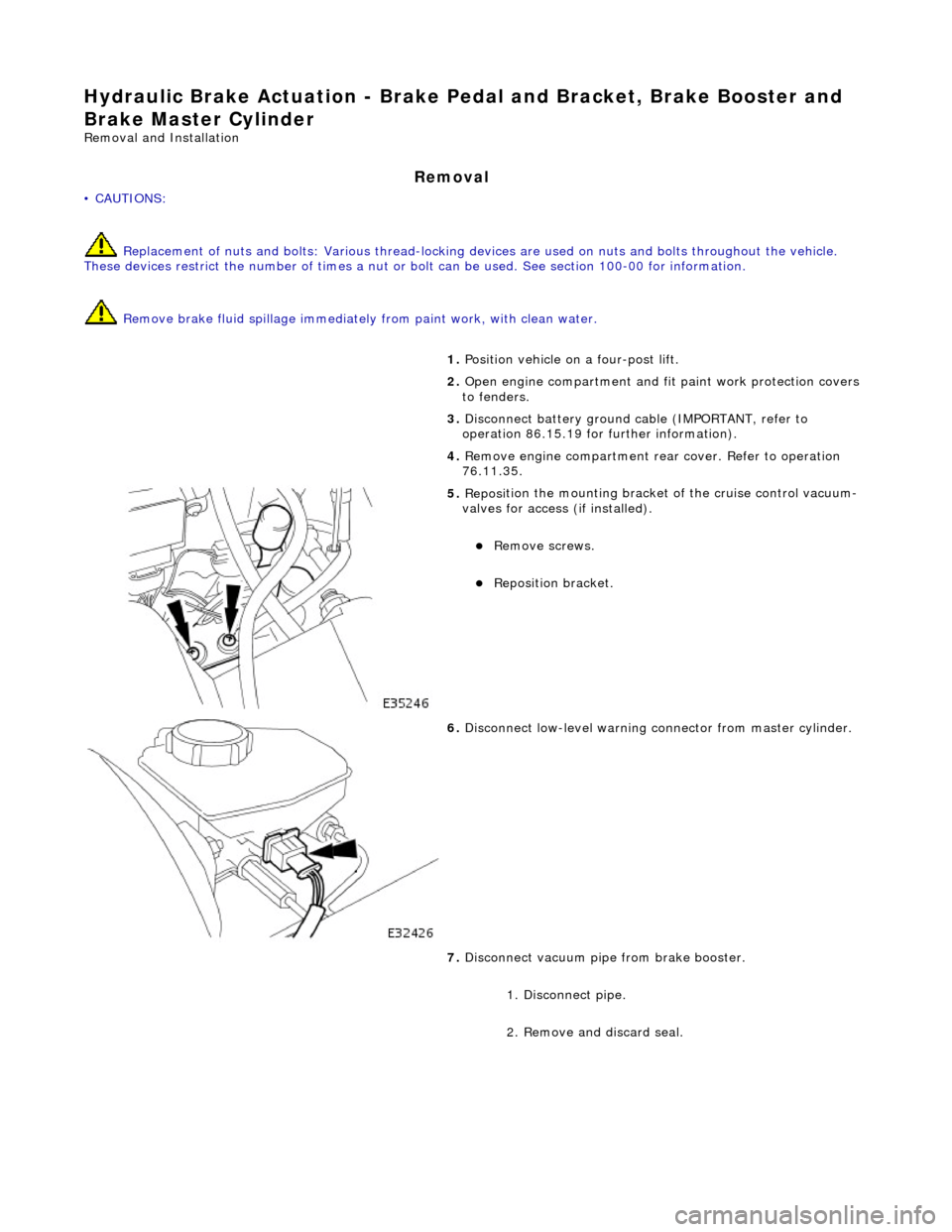
Hydrau
lic Brake Actuation - Brake Pedal and Bracket, Brake Booster and
Brake Master Cylinder
Re mo
val and Installation
Remova
l
• C
A
UTIONS:
Replacement of nuts and bolts: Various thread-locking de vices are used on nuts and bolts throughout the vehicle.
These devices restrict the number of times a nut or bolt can be used. See section 100-00 for information.
Remove brake fluid spilla ge immediately from paint work, with clean water.
1. Position vehi cl
e on a four-post lift.
2. Open engine compartment and fit paint work protection covers
to fenders.
3. Disconnect battery ground cable (IMPORTANT, refer to
operation 86.15.19 for fu rther information).
4. Remove engine compartment rear cover. Refer to operation
76.11.35.
5. Reposi
tion the mounting bracket of the cruise control vacuum-
valves for access (if installed).
R e
move screws.
Reposition bracket.
6. Disc
onnect low-level warning connector from master cylinder.
7. Disconnect vacuum pipe from brake booster.
1. Disconnect pipe.
2. Remove and discard seal.
Page 420 of 2490
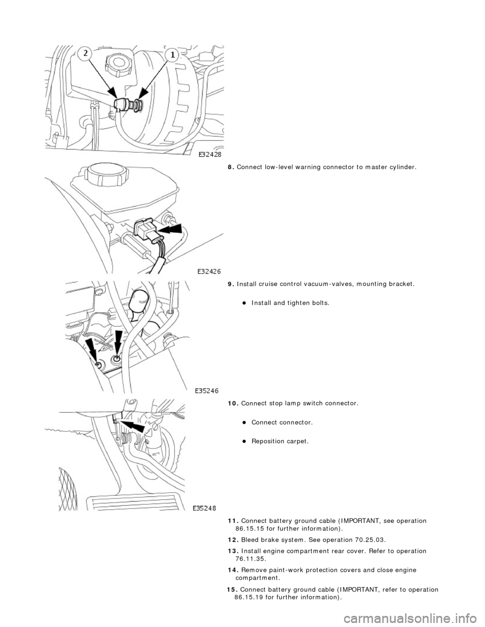
8. Conne ct
low-level warning connector to master cylinder.
9. Inst al
l cruise control vacuum-valves, mounting bracket.
Install and tigh
ten bolts.
10 . Conne
ct stop lamp switch connector.
Conne
ct
connector.
Re
posi
tion carpet.
11. Connect battery ground cable (IMPORTANT, see operation
86.15.15 for further information).
12. Bleed brake system. See operation 70.25.03.
13. Install engine compartment rear cover. Refer to operation
76.11.35.
14. Remove paint-work protection covers and close engine
compartment.
15 . Conne
ct battery ground cable (I
MPORTANT, refer to operation
86.15.19 for further information).
Page 422 of 2490
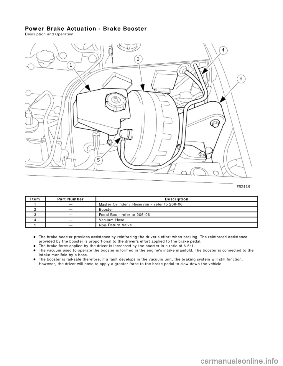
Power Brake Actuation - Brake Booster
Description and Operation
The brake b
ooster provides assi
stance by reinforcing the driver's effort when brakin g. The reinforced assistance
provided by the booster is proportional to the driver's effort applied to the brake pedal.
The brake force applied by
the driver is incr
eased by the booster in a ratio of 6.5:1.
Th
e vacuum used to operate the booster
is formed in the engine's intake manifold. The booster is connected to the
intake manifold by a hose.
The boost
er is fail-safe therefore, if a fault develops in
the vacuum unit, the braking system will still function.
However, the driver will have to apply a greater fo rce to the brake pedal to slow down the vehicle.
It e
m
Par
t
Number
De
scr
iption
1—Mas
t
er Cylinder / Reservoir - refer to 206-06
2—Booster
3—Pedal Box
- refer to 206-06
4—Vacuu
m
Hose
5—No
n
-Return Valve
Page 431 of 2490
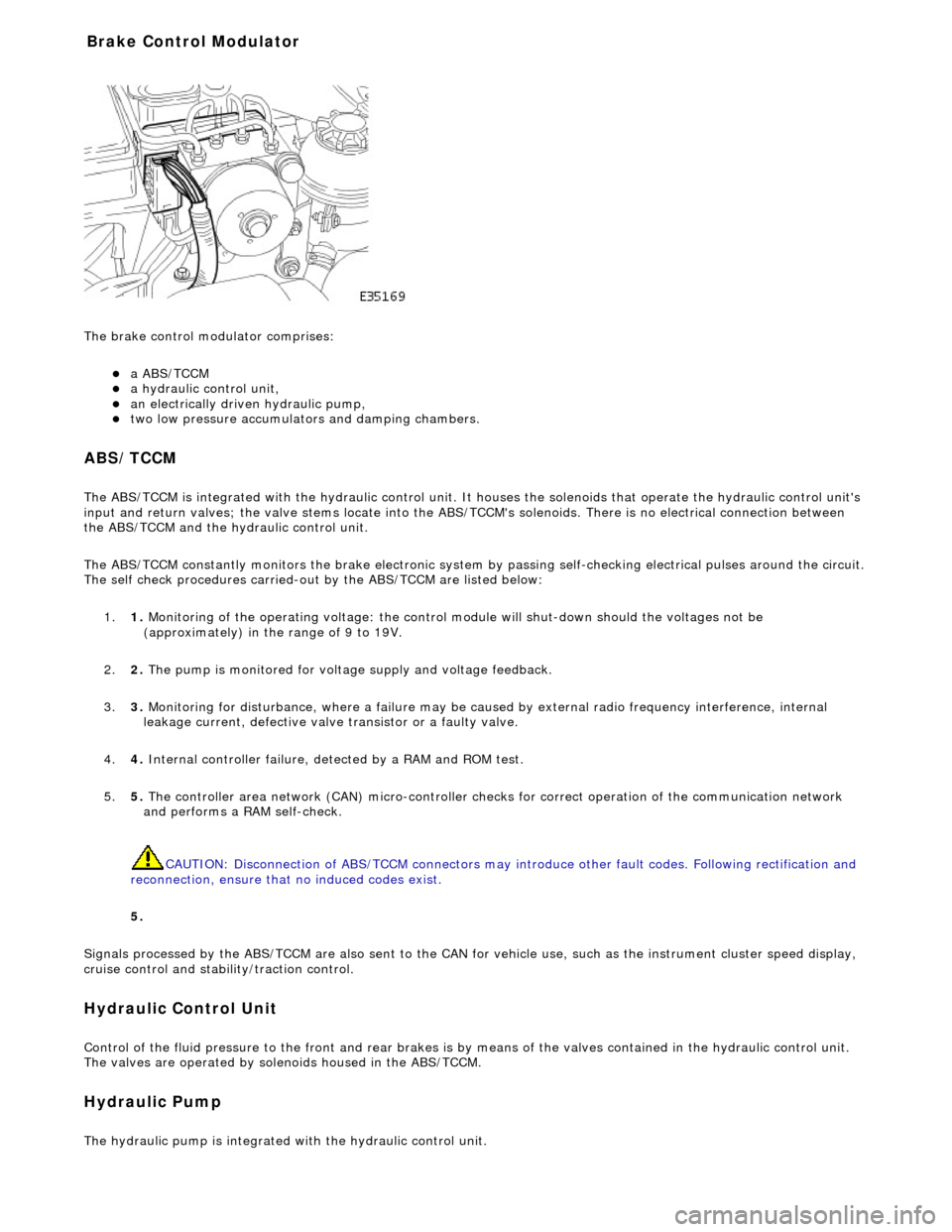
The brake
control modulator comprises:
a A
BS/TCCM
a h
ydraulic control unit,
an electrically driven hydrau
lic pump,
two low pressure accumulato
rs and damping chambers.
ABS/TCCM
The AB
S/TCCM is integrated with the hydrau
lic control unit. It houses the solenoids that operate the hydraulic control unit's
input and return valves; the valve stems locate into the ABS/TCCM's solenoids. There is no electrical connection between
the ABS/TCCM and the hydraulic control unit.
The ABS/TCCM constantly monitors the brake electronic system by passing self-checking electrical pulses around the circuit.
The self check procedures carried-out by the ABS/TCCM are listed below:
1. 1. Monitoring of the operating voltage: the control mo dule will shut-down should the voltages not be
(approximately) in the range of 9 to 19V.
2. 2. The pump is monitored for volt age supply and voltage feedback.
3. 3. Monitoring for disturbance, where a failure may be caus ed by external radio frequency interference, internal
leakage current, defective valve transistor or a faulty valve.
4. 4. Internal controller failure, de tected by a RAM and ROM test.
5. 5. The controller area network (CAN) micr o-controller checks for correct operation of the communication network
and performs a RAM self-check.
CAUTION: Disconnection of ABS/TCCM connectors may introduce other fault codes. Following rectification and
reconnection, ensure that no induced codes exist.
5.
Signals processed by the ABS/TCCM are also sent to the CAN for vehicle use, such as the instrument cluster speed display,
cruise control and stability/traction control.
Hydraulic Control Unit
Control of
the fluid pressure to
the front and rear brakes is by means of the valves contained in the hydraulic control unit.
The valves are operated by solenoids housed in the ABS/TCCM.
Hydraulic Pump
The
hydraulic pump is integrated
with the hydraulic control unit.
Bra
ke Control Modulator
Page 432 of 2490
It is a reciprocating two
-circuit pu
mp in which one brake circuit is as signed to each pump circuit.
It supplies th
e fluid pressure and vo
lume to supply the brake circuits under ABS and Traction control.
The pump is driven by an electri
c motor, with the pump
housing incorporating two lo w pressure accumulators and
damping chambers for each brake circuit.
The ac cu
mulator stores the pressure and smooths out the output pu
lses from the pump.
ABS Warning Lamp
The sys
tem will be set in a fail-safe mode if a problem is de
tected; a warning lamp on the instrument panel will notify the
driver there is a problem.
Anti-Lock Braking Sy
stem (ABS)
The AB
S components are combined with
an hydraulic booster and a tandem master cylinder to provide a two circuit braking
system. The system comprises, four wheel speed sensor s, a brake control modulator and an ABS warning lamp.
Should a wheel start to lock-up during braking a signal tr ansmitted from the wheel speed sensor to the brake control
modulator will start the hydraulic pump. The brake control modula tor will close the input valve of the line connected to the
locked-wheel to stop any increase in fluid pressure to the br ake caliper. If this fails to prevent the wheel locking, the
pressure in the caliper will be decreased by opening the return valve until th e wheel starts accelerating again. The fluid
pressure from the return va lve is directed into the low pressure accumulator, housed in the pump.
From the low pressure accumulator, fl uid is pumped through the damping cham ber to the brake master cylinder. The
pressure to the brake caliper will then be increased in small steps to maintain maximum adhesion between the tire and road
surface. This is achieved by closing the return valve, and opening the input valve and using the hydraulic pump to increase
the pressure.
Although the system senses all four wheels independently, the rear wheels are regulated as a pair. If a sensor on a rear
wheel detects a wheel decelerating rapidly, then the fluid pressure to both wheels is reduced. The fluid pressure is then
dictated by the wheel having the lowe st adhesion with the road surface.
The ABS system will be set in a fail-safe mode if a problem is detected; a warn ing lamp on the instrument panel will notify
the driver there is a problem. The brake system will still operate conventionally and with the same standard of performance
as a vehicle not equipped with ABS.
Automa tic Stability Control (ASC)
Th
e ASC utilizes the ABS sensing arrangement to provide the maximum traction force to propel the vehicle.
The ASC is switched on when the engine is started. The system can be switched off by pressing the 'ASC OFF' (the switched
is marked 'TRAC OFF' on vehicles fitted with traction control). The switch, which is situated in the center console switchpack,
lights up to warn that the system is sw itched off. An 'ASC' amber warning light flashes on the instrument panel when the
system detects a spinning wheel.
The ASC system uses engine intervention to reduce the torque delivered to the drive wheels to prevent them spinning.
Engine torque is re duced in three ways:
The
throttle is moved towards the closed position.
The ignition is retarded. F
u
el is cut-off at the cylinder injectors.
Wheel spin is detected by the wheel sp eed sensors and communicated to the AB S/TCCM. The ABS/TCCM uses information
from the controller area network (CAN) to calculate the torque that the engine should produce to stop the wheel spinning.
Torque reductions are then requested from the engine control module (ECM ) through the CAN. The throttle is then
positioned to provide the target torque, which has been calculated to prevent wheel spin. During the transient phase of
torque reduction the fuel is cut-off and th e ignition retarded Both the fuel cut-off an d ignition retard will be restored to
normal when the throttle is set to its new position.
The ASC uses a brake control modulator with six solenoid va lves: three normally open inlet valves and three normally
Page 433 of 2490
clos
ed outlet valves.
Traction Control
Trac
tion control has the same capabilities as ASC but with th
e added ability to actuate the brakes of the spinning wheel.
This enhances ASC by improving acceleration particularly on surfaces with uneven friction , e.g. one wheel on ice the other
on tarmac.
When wheelspin occurs, brake line pressure to the slipping wheel is generated, to operate that wheel's brake. The BCM
achieves this by closing the cut-off solenoid valve and oper ating the hydraulic pump. Brake fluid is then drawn from the
reservoir through the non-actuated mast er cylinder to the brake caliper.
A 'TRAC' amber warning light flashes on the instrument panel when the system detects a spinning wheel.
The traction control system uses a brake control modulator with nine solenoid valv es: four normally open inlet valves and
four normally closed outlet valves and one special isolating va lve. The outlet valves control the brakes of each each rear
wheel individually on the traction control system.
Rear Wheel Speed Senso
rs and ABS/TCCM Circuit Diagram