JAGUAR X308 1998 2.G Workshop Manual
X308 1998 2.G
JAGUAR
JAGUAR
https://www.carmanualsonline.info/img/21/7640/w960_7640-0.png
JAGUAR X308 1998 2.G Workshop Manual
Page 1543 of 2490
Is the voltage 0 (zero) V?
Yes GO to A16
No Inspect harness / connectors EM010, EM012, and EM021 for
corrosion, damaged / pushed back pins. Repair as necessary
and reconnect plug(s).
GO to A18
A16: CHECK FOR SHORT TO B+ AT O2 SENSOR HEATER
Page 1544 of 2490
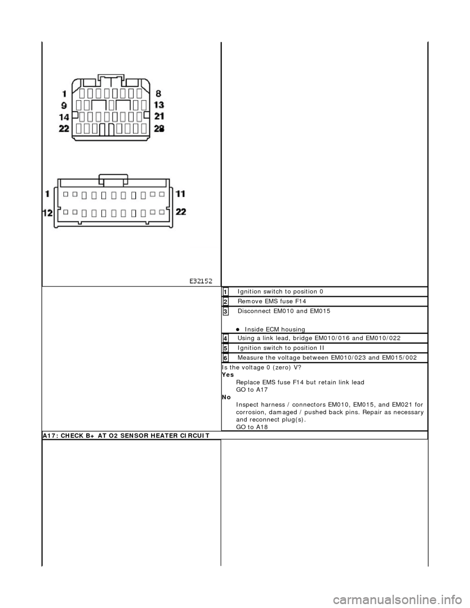
Ignition switch to position 0 1
Remove EMS fuse F14 2
Disconnect EM010 and EM015
пЃ¬Inside ECM housing
3
Using a link lead, bridge EM010/016 and EM010/022 4
Ignition switch to position II 5
Measure the voltage between EM010/023 and EM015/002 6
Is the voltage 0 (zero) V?
Yes Replace EMS fuse F14 but retain link lead
GO to A17
No Inspect harness / connectors EM010, EM015, and EM021 for
corrosion, damaged / pushed back pins. Repair as necessary
and reconnect plug(s).
GO to A18
A17: CHECK B+ AT O2 SENSOR HEATER CIRCUIT
Page 1545 of 2490
Pinpoint test B: P0133
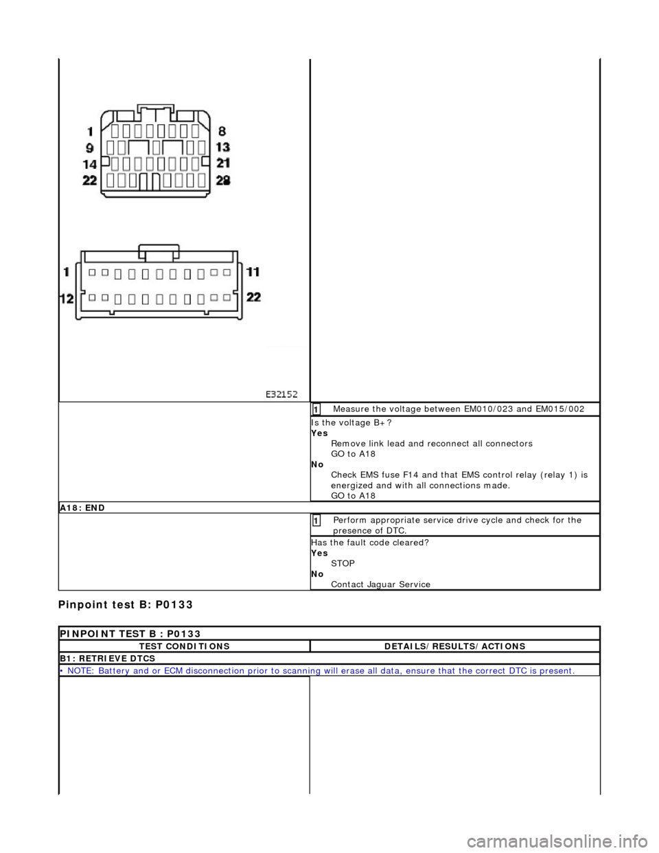
Measure the voltage between EM010/023 and EM015/002 1
Is the voltage B+?
Yes Remove link lead and reconnect all connectors
GO to A18
No Check EMS fuse F14 and that EMS control relay (relay 1) is
energized and with all connections made.
GO to A18
A18: END
Perform appropriate service drive cycle and check for the
presence of DTC. 1
Has the fault code cleared?
Yes STOP
No Contact Jaguar Service
PINPOINT TEST B : P0133
TEST CONDITIONSDETAILS/RESULTS/ACTIONS
B1: RETRIEVE DTCS
• NOTE: Battery and or ECM disconnection prior to scanning wi ll erase all data, ensure that the correct DTC is present.
Page 1550 of 2490
With EM010 and EM014 disconnected, measure the
resistance between EM010/023 and chassis ground EM008L. 1
Is the resistance < 0.5 OHM?
Yes GO to B12
No Inspect connector EM010 for co rrosion, damage, or pushed
back pins.
Inspect earthing stud EM008L for corrosion.
Inspect harness, splice EMS36.
Repair as required an d reconnect plug(s).
GO to B13
B12: SIGNAL GROUND 2 CONTINUITY
Page 1551 of 2490
With EM010 and EM014 disconnected, measure the
resistance between EM014/004 and chassis ground EM008L. 1
Is the resistance < 0.5 OHM?
Yes GO to B14
No Inspect connector EM014 for co rrosion, damage, or pushed
back pins.
Inspect earthing stud EM008L for corrosion.
Inspect harness, splice EMS36.
Repair as required an d reconnect plug(s).
GO to B13
B13: CHECK FOR HEATED O2 SENSOR CONTINUITY
Page 1552 of 2490
With EM012 and EM021 disconnected, measure the
resistance between EM012/015 and EM021/003. 1
Is the resistance < 0.5 OHM?
Yes GO to B14
No Inspect harness / connectors EM012 and EM021 for
corrosion, damaged / pushed back pins. Repair as necessary
and reconnect plug(s).
GO to B19
B14: HEATED O2 SENSOR SCREEN GROUND CONTINUITY
Page 1553 of 2490
With EM012 and EM021 disconnected, measure the
resistance between EM012/022 and EM021/004. 1
Is the resistance < 0.5 OHM?
Yes GO to B15
No Inspect connectors EM012 and EM021 for corrosion,
damaged / pushed back pins.
Inspect harness / splice EM S08 for damage. Repair as
necessary and reconnect plug(s).
GO to B19
B15: CHECK FOR SHORT TO B+
Page 1554 of 2490
Ignition switch to position 0 1
Disconnect EM010
пЃ¬Inside ECM housing
2
Disconnect EM012
пЃ¬Inside ECM housing
3
Ignition switch to position II 4
Measure the voltage between EM010/023 and EM012/015. 5
Is the voltage 0 (zero) V?
Yes GO to B16
No Inspect harness / connectors EM010, EM012 and EM021 for
corrosion, damaged / pushed back pins. Repair as necessary
and reconnect plug(s).
GO to B19
B16: CHECK FOR SHORT TO B+
Measure the voltage between EM010/023 and EM012/022 1
Page 1555 of 2490
Is the voltage 0 (zero) V?
Yes GO to B17
No Inspect harness / connectors EM010, EM012 and EM021 for
corrosion, damaged / pushed back pins. Repair as necessary
and reconnect plug(s).
GO to B19
B17: CHECK FOR SHORT TO B+ AT O2 SENSOR HEATER
Page 1556 of 2490
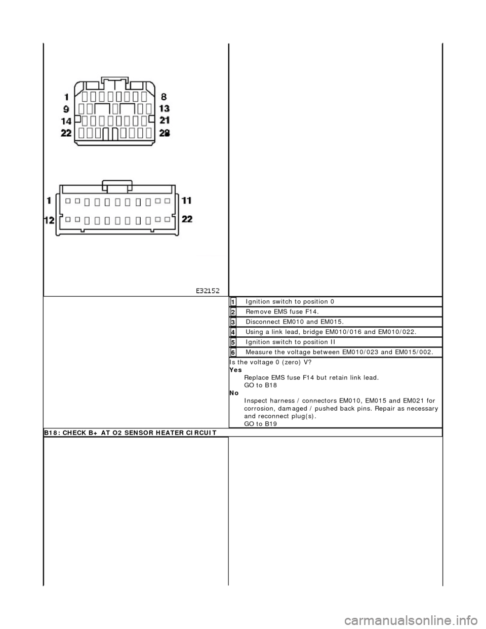
Ignition switch to position 0 1
Remove EMS fuse F14. 2
Disconnect EM010 and EM015. 3
Using a link lead, bridge EM010/016 and EM010/022. 4
Ignition switch to position II 5
Measure the voltage between EM010/023 and EM015/002. 6
Is the voltage 0 (zero) V?
Yes Replace EMS fuse F14 but retain link lead.
GO to B18
No Inspect harness / connectors EM010, EM015 and EM021 for
corrosion, damaged / pushed back pins. Repair as necessary
and reconnect plug(s).
GO to B19
B18: CHECK B+ AT O2 SENSOR HEATER CIRCUIT


