Connector JAGUAR X308 1998 2.G Workshop Manual
[x] Cancel search | Manufacturer: JAGUAR, Model Year: 1998, Model line: X308, Model: JAGUAR X308 1998 2.GPages: 2490, PDF Size: 69.81 MB
Page 1436 of 2490

Automatic Transmission/Transaxle - 4.0L SC V8 - AJ26 - Main Control
Valve Body
In-vehicle Repair
Removal
• NOTE: This procedure will not remove re sidual fluid from the torque converter.
1. Disconnect the battery ground lead.
2. Raise the vehicle for access.
3. Remove the RH catalytic converter; refer to Operation
17.50.10.
4. Remove the harness heatshield lower fixing.
пЃ¬Remove the screw heatshield / fluid pan clamp.
5. Remove the harness heatshield.
пЃ¬Pull the heatshield from under the clip.
6. Disconnect the transmission link harness connector.
1. Release the locking lever.
7. Release the (transmission case mounted) female connector.
пЃ¬Remove the (center) retaining bolt.
Page 1438 of 2490

Installation
13. Remove the valve body assembly.
пЃ¬Remove the nine bolts which re tain the valve body to the
transmission case.
1. Installation is the re verse of the removal procedure, noting the
following:
2. Clean all mating faces and relevant parts.
3. Tighten the nine bolts securing the valve body, to the specified
torque figure.
4. Refit the dowel (leaf spring to valve body) and the leaf spring.
Fit and tighten the securing bolt to the specified torque figure.
5. Tighten the centre retaining bolt of the electrical connector to
the specified torque figure.
Page 1443 of 2490

Automatic Transmission/Transaxle - 4.0L SC V8 - AJ26 - Transmission
Internal Wiring Harness Electr ical Connector O-Ring Seals
In-vehicle Repair
Removal
1. Disconnect the batt ery ground cable.
2. Open the engine compartment and fit paint protection sheets.
3. Raise the vehicle for access.
4. WARNING: TRANSMISSION FLUID MAY CAUSE SEVERE
BURNS, ENSURE THAT ALL SAFET Y PROCEDURES ARE OBSERVED
AND THAT THE RECEPTACLE FOR WASTE HAS SUFFICIENT
CAPACITY.
Drain the transmission fluid.
пЃ¬Carefully remove the drain pl ug and discard the sealing
washer.
5. Remove the harness heatshield lower fixing.
пЃ¬Remove the screw heatshield / fluid pan clamp.
6. Remove the harness heatshield.
пЃ¬Pull the heatshield from under the clip.
7. Disconnect the transmission link harness connector.
1. Release the locking lever on the guide bush and disconnect the harness connector.
Page 1444 of 2490

Installation
8. Release the connector guide bush from the transmission case.
пЃ¬Release the (center) retaining bolt; remains captive in the
guide bush.
9. Remove the guide bush from the transmission casing.
пЃ¬Very carefully, pry the guid e bush from the transmission
casing using a screwdriver ag ainst the cast lug on the
casing.
10. Remove and discard the sealing rings.
пЃ¬Note the position and size of each ring.
1. Installation is the re verse of the removal procedure, noting the
following:
2. Clean all mating faces and relevant parts.
3. Lubricate the new sealing rings using clean transmission fluid.
Page 1445 of 2490

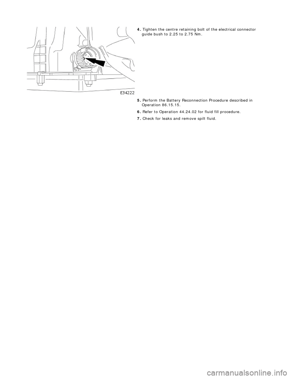
4. Tighten the centre retaining bolt of the electrical connector
guide bush to 2.25 to 2.75 Nm.
5. Perform the Battery Reconnection Procedure described in
Operation 86.15.15.
6. Refer to Operation 44.24.02 for fluid fill procedure.
7. Check for leaks and remove spilt fluid.
Page 1448 of 2490

Automatic Transmission/Transaxle - 4.0L SC V8 - AJ26 - Transmission
Removal
Removal
Special Tool(s)
Engine support
303-021
Engine lifting brackets
303-536
1. Select N gear position.
2. Disconnect the battery ground lead.
3. Remove the engine covers. Re fer to Operation 12.30.06.
4. Remove the air intake tube, MAFM and air cleaner cover
assembly. Refer to Operation 19.10.30.
5. Disconnect the transmission link lead connector.
1. Release the connector fr om its mounting bracket.
2. Disconnect the multiplug.
6. Remove the EMS harness mounting bracket.
пЃ¬Release the bolt, bracket to cylinder head.
7. Fit engine lifting bracket 307 - 536 at the rear RH.
Page 1460 of 2490

10. Refit the harness connector support bracket and tighten the
two bolts to the specified torque figure, noting that one fixing
also retains the di pstick upper tube.
11. Connect the selector cable. Ti ghten the bolts and one nut to
the specified torque figure.
12. Connect the driveshaft (prop-shaft) aligning the marks made
when it was removed. Tighten the bolts to the specified torque
figure.
13. Fit the rear crossmember. Tighten the bolts to the specified
torque figure.
Page 1464 of 2490

Automatic Transmission/Transaxle External Controls - 4.0L NA V8 -
AJ27/3.2L NA V8 - AJ26 - External Controls
Description and Operation
Introduction
Driver gearshift control is effected by:
пЃ¬The gear shift lever. пЃ¬The accelerator pedal position. пЃ¬The kickdown switch (where fitted). пЃ¬The performance mode pushbutton.
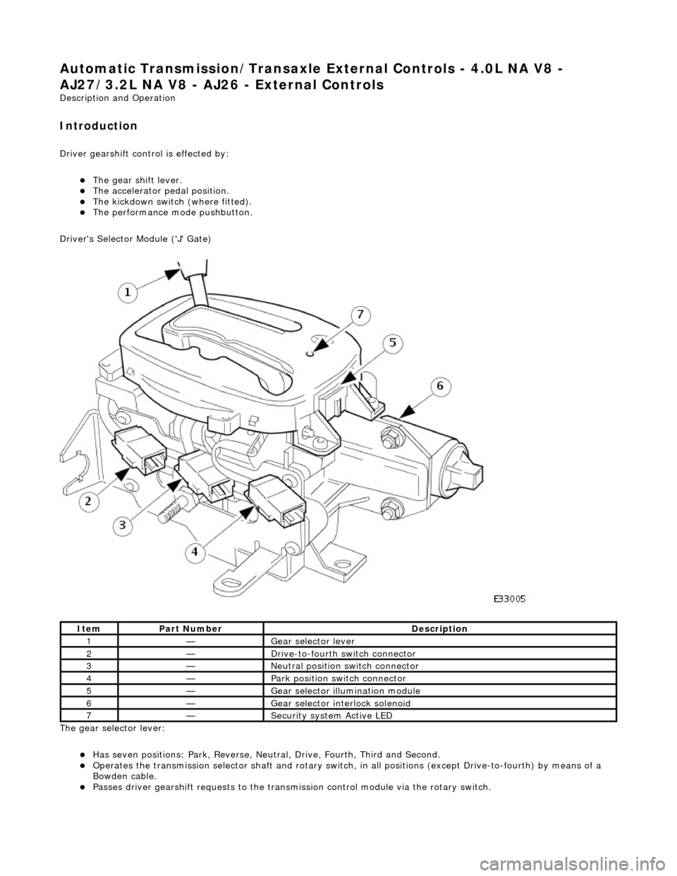
Driver's Selector Module ('J' Gate)
The gear selector lever:
пЃ¬Has seven positions: Park, Reverse, Neutral, Drive, Fourth, Third and Second. пЃ¬Operates the transmission selector shaft and rotary switch, in all positions (except Drive-to-fourth) by means of a
Bowden cable.
пЃ¬Passes driver gearshift requests to the transm ission control module via the rotary switch.
ItemPart NumberDescription
1—Gear selector lever
2—Drive-to-fourth switch connector
3—Neutral position switch connector
4—Park position switch connector
5—Gear selector illumination module
6—Gear selector interlock solenoid
7—Security system Active LED
Page 1465 of 2490

The Drive-to-fourth switch:
пЃ¬Detects when the gear selector lever is moved from Drive to Fourth. пЃ¬Is hard-wired to the transmission control module.
The Neutral position switch:
пЃ¬Is hard-wired to the body processor module. пЃ¬Detects when the gear selector lever is moved to the Neutral position.
The Park position switch:
пЃ¬Is hard-wired to the body processor module. пЃ¬Detects when the gear selector leve r is moved to the Park position.
The gear selector module:
пЃ¬Provides illumination of the gear sele ctor surround, which is dimmable via a CA N signal from the instrument cluster. пЃ¬Provides red illumination, on the gear selector surround, of the gear selected, by CAN signals from the instrument
cluster.
пЃ¬Illuminates the security system Active LED on the gear se lector surround, in response to an input from the body
processor module.
пЃ¬Is connected to the fascia harness via a 12-way connector. Refer to Connec tor Pins Identification, 307-01A.
The gear selector interlock solenoid:
пЃ¬Prevents the gear selector lever from be ing moved from the Park position, unless th e ignition switch is in position II,
and the brake pedal is depressed.
пЃ¬Is controlled by an input from the body processor module.
The seven gear selector positions are:
пЃ¬P : The transmission is mechanically locked (starting available). пЃ¬R : Reverse gear. пЃ¬N : No power to the rear wh eels (starting available). пЃ¬D : All 5 forward gears available. пЃ¬4 : Upshift to 4th gear only. пЃ¬3 : Upshift to 3rd gear only. пЃ¬2 : Upshift to 2nd gear only.
Performance Mode Pushbutton
The performance mode pushbutton:
пЃ¬Is mounted on the gear selector surround. пЃ¬Selects Normal or Sport mode when pressed by the driver. пЃ¬Is illuminated when Sport mode is selected.
Page 1469 of 2490

Automatic Transmission/Transaxle External Controls - 4.0L NA V8 -
AJ27/3.2L NA V8 - AJ26 - External Controls
Diagnosis and Testing
Symptom Chart
Symptom Chart
Pinpoint test A: P0706
Special Tool(s)
Digital multimeter
Generic scantool
SymptomPossible SourcesAction
DTC P0706 Transmission range sensor circuit range /
performanceSelector cable maladjusted
Rotary switch fault
D to 4 switch fault
Rotary position switch fault
Harness fault
Connector pins(s) bent, loose or
corroded
*
*
*
*
*
*GO to Pinpoint Test A
*
PINPOINT TEST A : P0706
TEST CONDITIONSDETAILS/RESULTS/ACTIONS
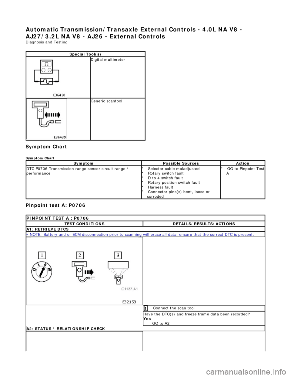
A1: RETRIEVE DTCS
• NOTE: Battery and or ECM disconnection prior to scanning wi
ll erase all data, ensure that the correct DTC is present.
Connect the scan tool 1
Have the DTC(s) and freeze frame data been recorded?
Yes GO to A2
A2: STATUS / RELATIONSHIP CHECK