JAGUAR X308 1998 2.G Workshop Manual
X308 1998 2.G
JAGUAR
JAGUAR
https://www.carmanualsonline.info/img/21/7640/w960_7640-0.png
JAGUAR X308 1998 2.G Workshop Manual
Page 1721 of 2490
Wi
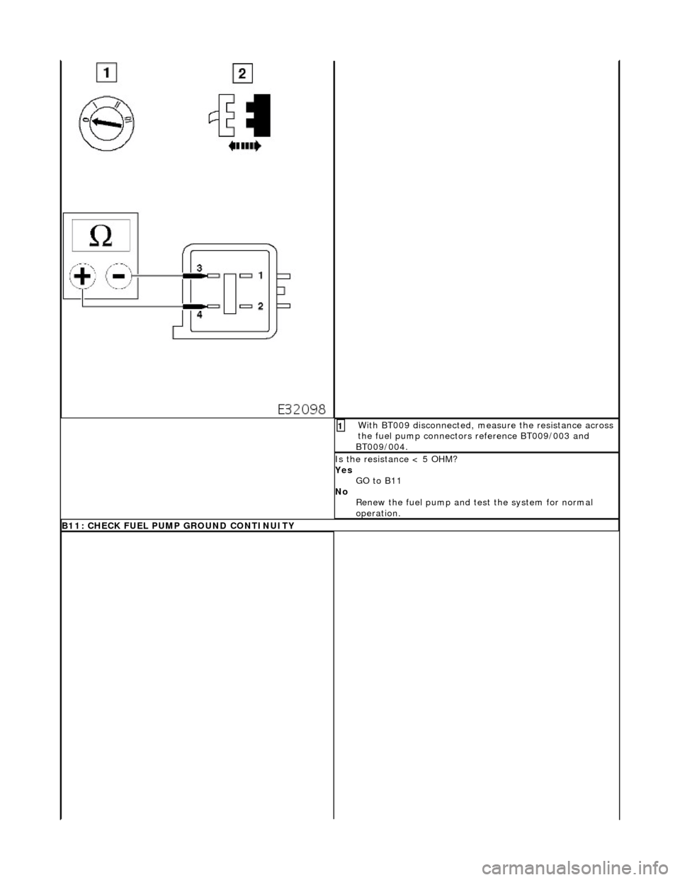
th BT009 disconnected, measure the resistance across
the fuel pump connectors reference BT009/003 and
BT009/004.
1
I
s the resistance < 5 OHM?
Yes GO to B11
No Renew the fuel pump and te st the system for normal
operation.
B11: CHECK FU
EL PUMP GROUND CONTINUITY
Page 1722 of 2490
With
BT009 disconnected, measure the resistance
between BT009/003 and ground BT020L.
1
I s
the resistance < 0.5 OHM?
Yes GO to B12
No Inspect harness / connector BT009, splice BTS021 and
ground BT020L for corrosion, damage, bent or pushed
back pins. Repair as requir ed and test the system for
normal operation.
B1 2
: CHECK CIRCUIT CONTINUITY
Page 1723 of 2490
Wi
th BT009 disconnected an
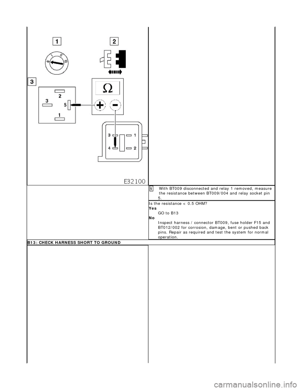
d relay 1 removed, measure
the resistance between BT009/004 and relay socket pin
5.
1
I
s the resistance < 0.5 OHM?
Yes GO to B13
No Inspect harness / connector BT 009, fuse holder F15 and
BT012/002 for corrosion, damage, bent or pushed back
pins. Repair as required and test the system for normal
operation.
B13: CHECK HARNESS SHO
RT TO GROUND
Page 1724 of 2490
Wi
th EM013 and BT009 disconnected, measure the
insulation resistance between EM013/009 and ground
BT020L.
1
I s
the resistance > 10M OHM?
Yes Do not replace relay or reconnect connectors
GO to B14
No Inspect harness / connec tors EM013, EM051/008,
LS003/021, BT004/009 and BT010/005 for corrosion,
damage, bent or pushed back pins. Repair as required
and test the system for normal operation.
B1 4
: CHECK CORE TO CORE INSULATION
Page 1727 of 2490
Conne
ct the scan tool
1
Have the DTC(s) and fr
eeze
frame data been recorded?
Yes GO to C2
C2
: CHECK CONTINUITY FUEL SENSOR
W
ith connectors BT014 and BT015 disconnected check
the resistance between the fuel level sensor pins.
1
Is
the resistance >70 and <1000 OHM?
Yes GO to C3
No Renew the level sensor and test the system for normal
operation.
C3
: CHECK FOR SHORT TO GROUND
Page 1728 of 2490
Wi
th connectors FC025, FC024, BT014 and BT015
disconnected measure the insulation resistance between
FC025/013 and FC024/026.
1
Re
peat for FC025/014 and FC024/026
2
Is
the resistance > 10 MOHM?
Yes GO to C4
No Inspect harness / connectors FC025, FC024, FC001,
BT004, BT014 and BT015 for corrosion, damage, bent or
pushed back pins. Repair as required and test the system
for normal operation.
C4 : CH
ECK CORE TO CORE INSULATION
Page 1729 of 2490
W
ith connectors FC025, FC024, BT014 and BT015
disconnected measure the insulation resistance between
FC025/013 and FC025/014.
1
I
s the resistance > 10 MOHM?
Yes GO to C5
No Inspect harness / connectors FC025, FC024, FC001,
BT004, BT014 and BT015 for corrosion, damage, bent or
pushed back pins. Repair as required and test the system
for normal operation.
C5
: CHECK GROUND CONTINUITY
Page 1730 of 2490
Wi
th connectors FC025, FC024 and BT015 disconnected
measure the resistance between FC025/014 and BT015.
1
I s
the resistance < 0.5 OHM?
Yes GO to C6
No Inspect harness / connectors / pins FC025, FC001/007,
BT004/026 and BT015 for corrosion, damage, bent or
pushed back pins. Repair as required and test the system
for normal operation.
C6 : CH
ECK SIGNAL CONTINUITY
Page 1731 of 2490
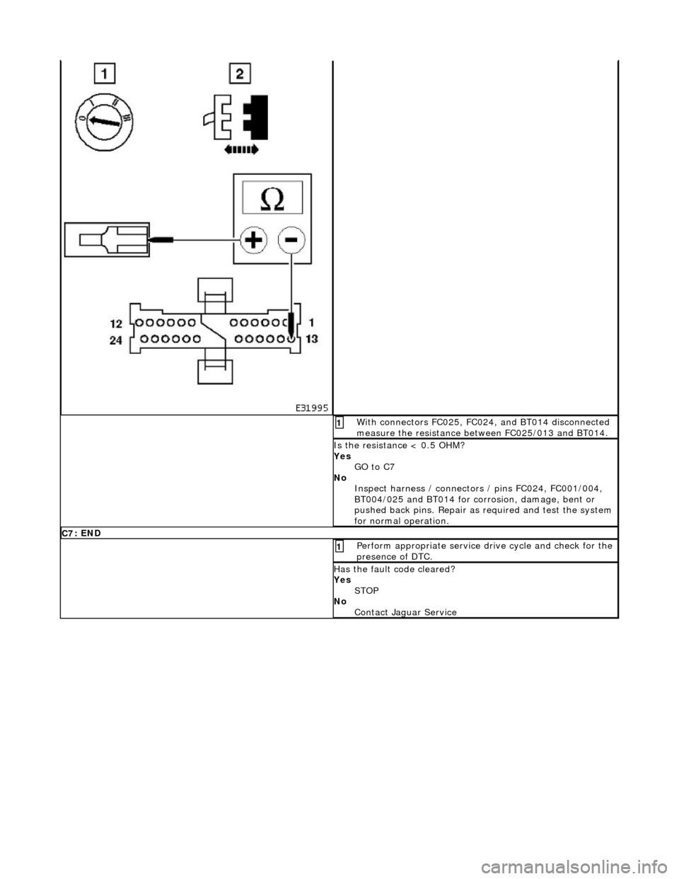
W
ith connectors FC025, FC024, and BT014 disconnected
measure the resistance between FC025/013 and BT014.
1
I
s the resistance < 0.5 OHM?
Yes GO to C7
No Inspect harness / connectors / pins FC024, FC001/004,
BT004/025 and BT014 for corrosion, damage, bent or
pushed back pins. Repair as required and test the system
for normal operation.
C7
: END
Perform
appropriate service drive cycle and check for the
presence of DTC.
1
Has
the fault code cleared?
Yes STOP
No Contact Jaguar Service
Page 1735 of 2490

10
.
Disconnect the fuel feed and return pipes from the fuel tank
пЃ¬F
it special tool JD-203 around
the pipe as shown. Press
the tool in between the fuel pipe and tank connector to
release the quick-fit tangs. While holding the tool firmly in,
pull out the fuel pipe.
пЃ¬Repeat
for the second pipe.
пЃ¬Plu
g the tank outlet connectors and the fuel pipes.
11
.
From the underside of the vehicl e, release the fuel filler latch
box drain pipe from the clip on the spare wheel well.
12
.
Disconnect and reposition the tr unk harness if it is routed
between the filler tube and the ta nk breather or pressure relief
pipe.
1. Disconnect the lefthand re ar lamp harness connector.
2. Disconnect the fuel flap lock actuator connector.
3. If fitted, disconnect the lefthand side marker lamp
connector and harness fro m the underside of the
vehicle. Withdraw the marker lamp harness and
grommet through the trunk floor access hole.
4. Release the harness securi ng clip from the mounting
bracket.
пЃ¬Wi
thdraw the trunk harness from between the filler tube
and the breather pipe or pressure relief pipe.
13. Disconnect the tank harness connections.


