Connector JAGUAR X308 1998 2.G Workshop Manual
[x] Cancel search | Manufacturer: JAGUAR, Model Year: 1998, Model line: X308, Model: JAGUAR X308 1998 2.GPages: 2490, PDF Size: 69.81 MB
Page 1637 of 2490

M
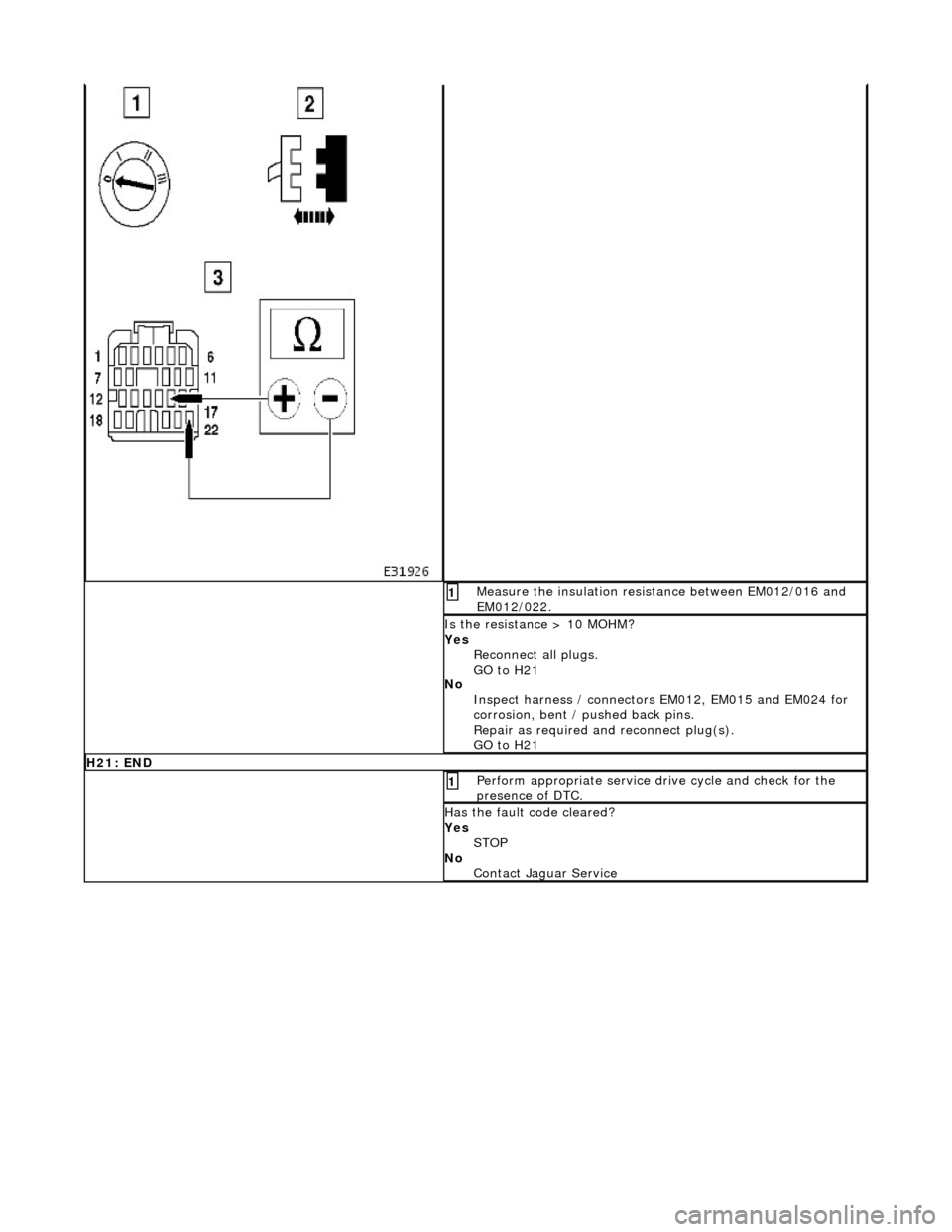
easure the insulation resistance between EM012/016 and
EM012/022.
1
I
s the resistance > 10 MOHM?
Yes Reconnect all plugs.
GO to H21
No Inspect harness / connectors EM012, EM015 and EM024 for
corrosion, bent / pushed back pins.
Repair as required an d reconnect plug(s).
GO to H21
H2
1: END
Perform
appropriate service drive cycle and check for the
presence of DTC.
1
Has
the fault code cleared?
Yes STOP
No Contact Jaguar Service
Page 1638 of 2490

Exha
ust System - Catalyti
c Converter LH4.0L NA V8 - AJ27/3.2L NA V8 -
AJ26
Re mo
val and Installation
Remova
l
1.
Op
en the engine compartment and fit paintwork protection
sheets.
2. Remove the front muffler; refer to Operation 30.10.18 in this
section.
3. Re
move the centre trim panel
from the engine compartment.
1. Remove the left hand side enclosure panel.
2. Remove the centre trim panel.
4. Repo
sition the expansion tank from the mounting.
1. Disconnect the coolant level sensor connector.
2. Remove the nuts which secures the tank.
5. CAUT
ION: Note the position of the upstream and
downstream (where fitted) o xygen sensor multiplugs for
reassembly.
Disconnect the oxygen sensor multiplugs.
пЃ¬Di spl
ace the multiplugs from the engine mounting bracket.
пЃ¬Dis
connect the plug(s) from the oxygen sensor(s)
6.
Re
move the four nuts which se
cure the downpipe catalytic
converter to the exhaust manifold.
Page 1641 of 2490

2.
Connect the harness connector
8. R
efit the centre trim panel and th
e left hand enclosure panel to
the engine compartment.
1. Refit the centre trim panel.
2. Refit the left hand enclosure panel.
9. Raise the ramp.
10
.
Tighten the mounting brac ket securing bolts.
11. Fit the front muffler; refer to Operation 30.10.18.
12. Lower the ramp.
13. Remove the paintwork protection sheets and close the engine
cover.
Page 1642 of 2490

Exha
ust System - Catalytic Conv
erter LH4.0L SC V8 - AJ26
Remo
val and Installation
Remov
a
l
1.
Op
en the engine compartment and fit paintwork protection
sheets.
2. Re
move the centre trim panel
from the engine compartment.
1. Remove the left hand side enclosure panel.
2. Remove the centre trim panel.
3. Repo
sition the expansion tank from the mounting.
1. Disconnect the coolant level sensor connector.
2. Remove the nuts which secures the tank.
4. CAUT
ION: Note the position of the upstream and
downstream (where fitted) o xygen sensor multiplugs for
reassembly.
Disconnect the oxygen sensor multiplugs.
пЃ¬Di spl
ace the multiplugs from the engine mounting bracket.
пЃ¬Dis
connect the plug(s) from the oxygen sensor(s)
5.
Re
move the four nuts which se
cure the downpipe catalytic
converter to the exhaust manifold.
Page 1645 of 2490

6. Connec
t the oxygen sensor multiplugs.
пЃ¬Con
nect the plug(s) to the respective (previously noted)
sensor(s).
пЃ¬Cor
rectly position the multiplu
gs on the mounting bracket.
7. F
it the coolant header tank.
1. Reposition the tank and fit the securing nuts.
2. Connect the harness connector
8. R
efit the centre trim panel and th
e left hand enclosure panel to
the engine compartment.
1. Refit the centre trim panel.
2. Refit the left hand enclosure panel.
9. Raise the vehicle on the ramp.
10. Tighten the mounting brac ket securing bolts.
Page 1654 of 2490

Exha
ust System - Catalyti
c Converter Gasket LH4. 0L NA V8 - AJ27/3.2L
NA V8 - AJ26
Re mo
val and Installation
Remova
l
1.
Op
en the engine compartment and fit paintwork protection
sheets.
2. Remove the front muffler; refer to Operation 30.10.18 in this
section.
3. Re
move the centre trim panel
from the engine compartment.
1. Remove the left hand side enclosure panel.
2. Remove the centre trim panel.
4. Repo
sition the expansion tank from the mounting.
1. Disconnect the coolant level sensor connector.
2. Remove the nuts which secures the tank.
5. CAUT
ION: Note the position of the upstream and
downstream (where fitted) o xygen sensor multiplugs for
reassembly.
Disconnect the oxygen sensor multiplugs.
пЃ¬Re
lease the multiplugs from th
e engine mounting bracket.
пЃ¬Dis
connect the plug(s) from the oxygen sensor(s)
6.
Re
move the four nuts which se
cure the downpipe catalytic
converter to the exhaust manifold.
Page 1656 of 2490

5. Connec t
the oxygen sensor multiplugs.
пЃ¬Con
n
ect the plug(s) to the respective (previously noted)
sensor(s).
пЃ¬Cor r
ectly position the multiplu
gs on the mounting bracket.
6. Fi
t the coolant header tank.
1. Reposition the tank and fit the securing nuts.
2. Connect the harness connector
7. Re
fit the centre trim panel and th
e left hand enclosure panel to
the engine compartment.
1. Refit the centre trim panel.
2. Refit the left hand enclosure panel.
8. Raise the ramp.
9. Tighten the mounting brac ket securing bolts.
Page 1658 of 2490

Exha
ust System - Cataly
tic Converter Gasket LH 4.0L SC V8 - AJ26
Remo
val and Installation
Remov
a
l
1.
Op
en the engine compartment and fit paintwork protection
sheets.
2. Re
move the centre trim panel
from the engine compartment.
1. Remove the left hand side enclosure panel.
2. Remove the centre trim panel.
3. Repo
sition the expansion tank from the mounting.
1. Disconnect the coolant level sensor connector.
2. Remove the nuts which secures the tank.
4. CAUT
ION: Note the position of the upstream and
downstream (where fitted) o xygen sensor multiplugs for
reassembly.
Disconnect the oxygen sensor multiplugs.
пЃ¬Di spl
ace the multiplugs from the engine mounting bracket.
пЃ¬Dis
connect the plug(s) from the oxygen sensor(s).
5.
Re
move the four nuts which se
cure the downpipe catalytic
converter to the exhaust manifold.
Page 1660 of 2490

In
stallation
1.
Fit a ne
w gasket to the mani
fold mating flange on the
downpipe.
2. Fit
the downpipe catalytic converter.
1. Fit the downpipe assembly to the manifold.
пЃ¬Fit,
but do not fully tighten, the mounting bracket securing
bolts. (Leave loose until the nu ts securing the downpipe to
the exhaust manifold are fitted.)
3. Lower the ramp.
4. Tigh te
n the nuts securing the downpipe flange to the manifold
flange.
5. Connec t
the oxygen sensor multiplugs.
пЃ¬Con
n
ect the plug(s) to the respective (previously noted)
sensor(s).
пЃ¬Cor r
ectly position the multiplu
gs on the mounting bracket.
6. Fi
t the coolant header tank.
1. Reposition the tank and fit the securing nuts.
2. Connect the harness connector
7. Refit the centre trim panel and th e left hand enclosure panel to
the engine compartment.
Page 1691 of 2490

Fuel System - Gener
al Information - Fuel Tank Draining
Gen
eral Procedures
1.
WARNING: BEFORE PROCEEDING, IT IS ESSENTIAL THAT
THE WARNING NOTES GIVEN IN SECTION 100-00 (UNDER THE
HEADING 'SAFETY PRECAUTIONS') ARE READ AND
UNDERSTOOD.
Remove the battery. Refer to operation 86.15.01.
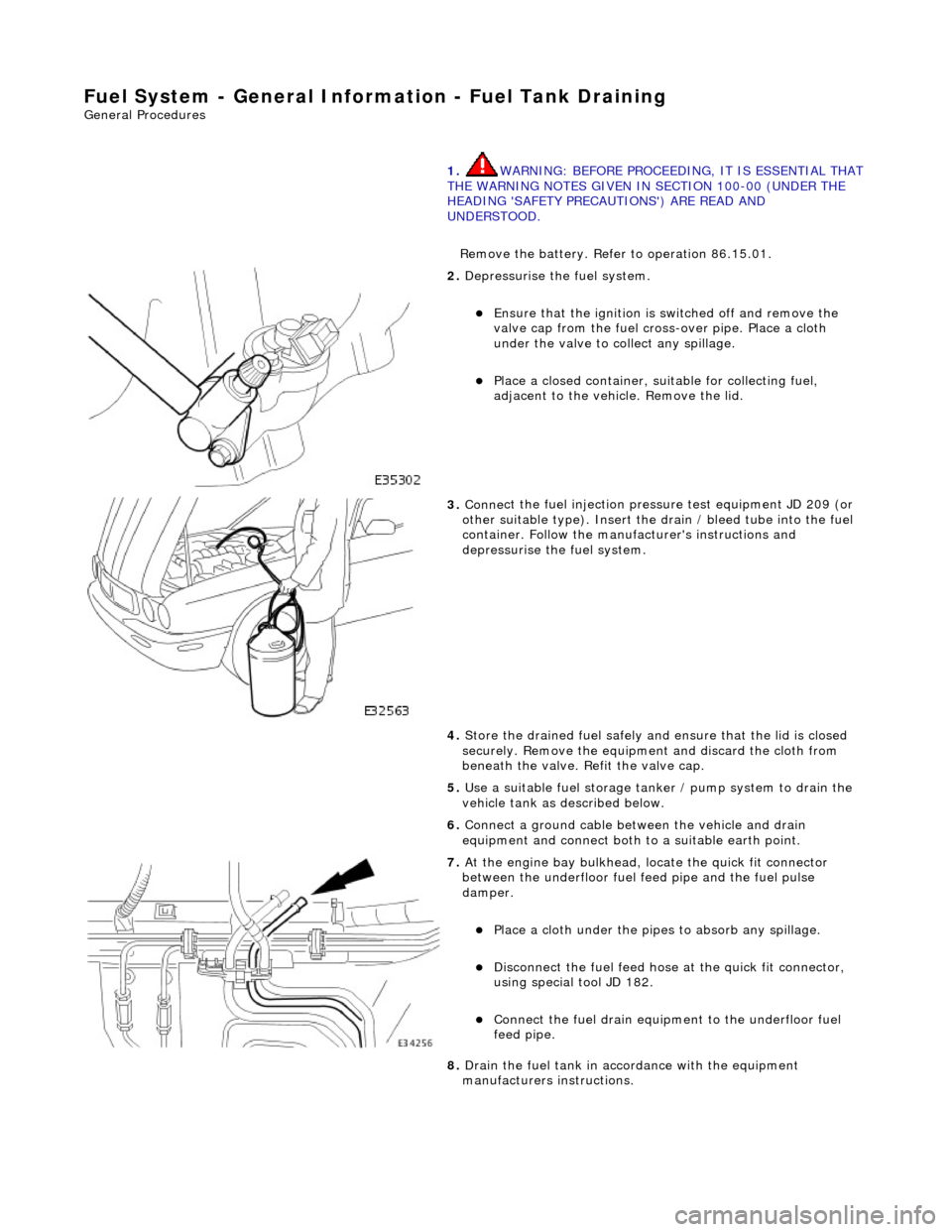
2. De
pressurise the fuel system.
пЃ¬E
nsure that the ignition is
switched off and remove the
valve cap from the fuel cross-over pipe. Place a cloth
under the valve to collect any spillage.
пЃ¬Pla
ce a closed container, su
itable for collecting fuel,
adjacent to the vehicle. Remove the lid.
3. Conne
ct the fuel injection pressu
re test equipment JD 209 (or
other suitable type). Insert the drain / bleed tube into the fuel
container. Follow the manufa cturer's instructions and
depressurise the fuel system.
4. Store the drained fuel safely and ensure that the lid is closed
securely. Remove the equipmen t and discard the cloth from
beneath the valve. Refit the valve cap.
5. Use a suitable fuel storage tank er / pump system to drain the
vehicle tank as described below.
6. Connect a ground cable betw een the vehicle and drain
equipment and connect both to a suitable earth point.
7. At the engine bay bulkhead, lo cate the quick fit connecto
r
between the underfloor fuel feed pipe and the fuel pulse
damper.
пЃ¬Pla
ce a cloth under the pipes
to absorb any spillage.
пЃ¬D
isconnect the fuel feed hose
at the quick fit connector,
using special tool JD 182.
пЃ¬Conne
ct the fuel drain equipment to the underfloor fuel
feed pipe.
8. Drain the fuel tank in accordance with the equipment
manufacturers instructions.