Connector JAGUAR X308 1998 2.G Workshop Manual
[x] Cancel search | Manufacturer: JAGUAR, Model Year: 1998, Model line: X308, Model: JAGUAR X308 1998 2.GPages: 2490, PDF Size: 69.81 MB
Page 1833 of 2490

Control Components - Control Components
Diagnosis and Testing
Connector Pin Identity Chart for AC001
Connector Pin Identity Chart for AC002
Pin NumberCircuitCircuit Function
001Compressor ON signal
002Coolant valve
003RH Blower motor relay
004Heated windshield relays (where fitted)
005Heated door mirror relay
006Defrost servomotor (positive)
007Center vent servomotor (positive)
008LH air intake servomotor fre sh / recirculation (positive)
009RH air intake servomotor fresh / recirculation (positive)
010Not used
011Not used
012Foot servomotor (positive)
013Cool air bypass servomotor (positive)
014Not used
015Not used
016LH Blower motor relay
017Coolant pump motor relay
018Heated backlight relay
019Defrost servomotor (negative)
020Center vent servomotor (negative)
021LH air intake servomotor fresh / recirculation (negative)
022RH air intake servomotor fresh / recirculation (negative)
023Not used
024Not used
025Foot servomotor (negative)
026Cool air bypass servomotor (negative)
Page 1834 of 2490
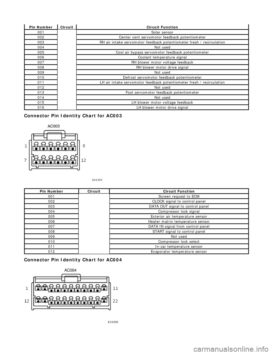
Connector Pin Identity Chart for AC003
Connector Pin Identity Chart for AC004
Pin NumberCircuitCircuit Function
001Solar sensor
002Center vent servomotor feedback potentiometer
003RH air intake servomotor feedback potentiometer fresh / recirculation
004Not used
005Cool air bypass servomotor feedback potentiometer
006Coolant temperature signal
007RH blower motor voltage feedback
008RH blower motor drive signal
009Not used
010Defrost servomotor feedback potentiometer
011LH air intake servomotor feedback potentiometer fresh / recirculation
012Not used
013Foot servomotor feedback potentiometer
014Not used
015LH blower motor voltage feedback
016LH blower motor drive signal
Pin NumberCircuitCircuit Function
001Screen request to ECM
002CLOCK signal to control panel
003DATA OUT signal to control panel
004Compressor lock signal
005Exterior air temperature sensor
006Heater matrix temperature sensor
007DATA IN signal from control panel
008START signal to control panel
009Not used
010Compressor lock select
011In-car temperature sensor
012Evaporator temperature sensor
Page 1835 of 2490
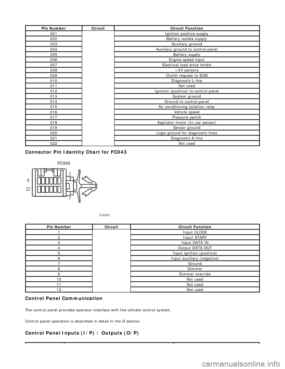
Connector Pin Identity Chart for FC043
Control Panel Communication
The control panel provides operator interface with the climate control system.
Control panel operation is described in detail in the D section.
Control Panel Inputs (I/P) / Outputs (O/P)
Pin NumberCircuitCircuit Function
001Ignition positive supply
002Battery isolate supply
003Auxiliary ground
004Auxiliary ground to control panel
005Battery supply
006Engine speed input
007Electrical load drive inhibit
008+5V sensors
009Clutch request to ECM
010Diagnostic L-line
011Not used
012Ignition (positive) to control panel
013System ground
014Ground to control panel
015Air conditioning isolation relay
016Vehicle speed
017Pressure switch
018Aspirator motor (In-car sensor)
019Sensor ground
020Logic ground for diagnostic lines
021Diagnostic K-line
022Not used
Pin NumberCircuitCircuit Function
1Input CLOCK
2Input START
3Input DATA IN
4Output DATA OUT
5Input ignition (positive)
6Input auxiliary (negative)
7Ground
8Dimmer
9Dimmer override
10Not used
11Not used
12Not used
Page 1837 of 2490
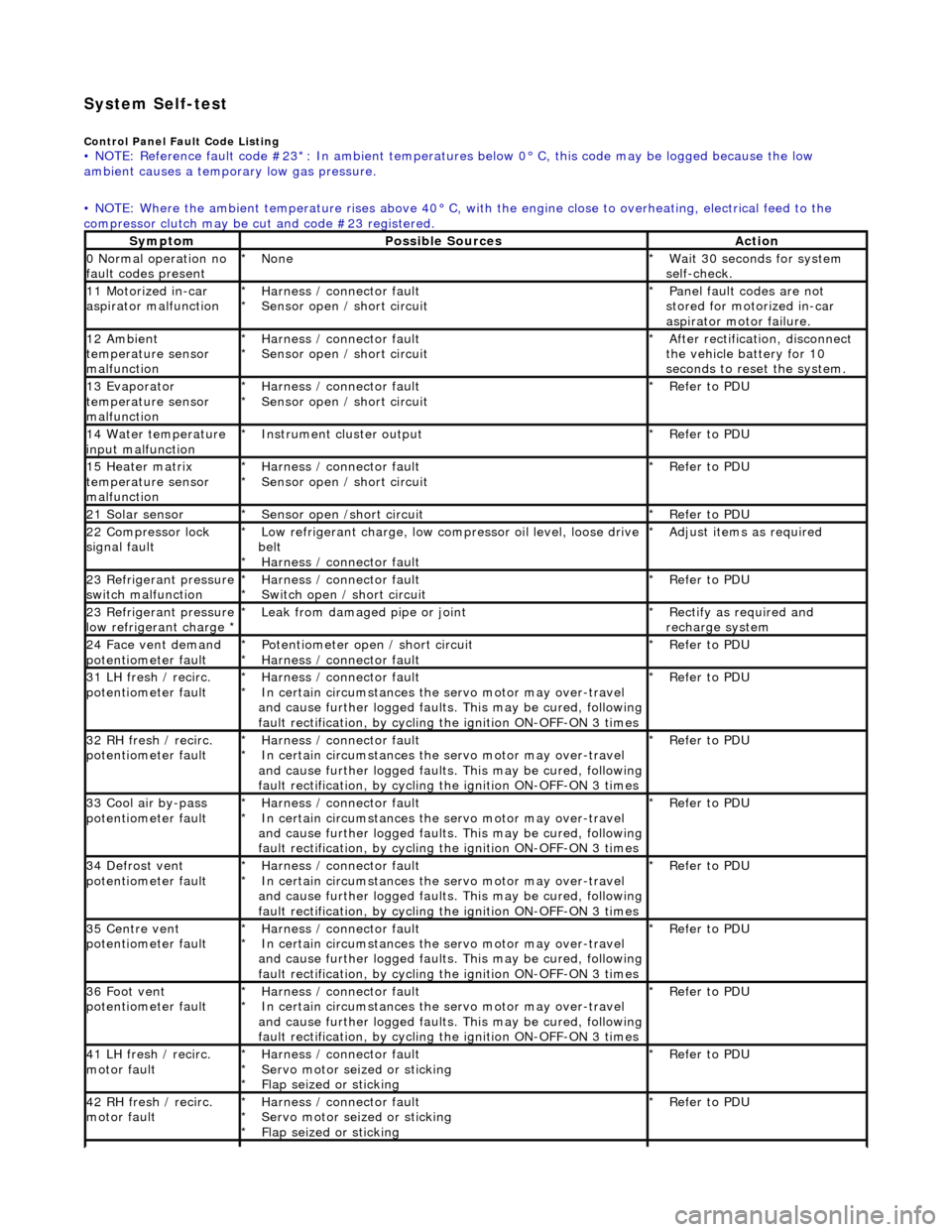
System Self-test
Control Panel Fault Code Listing • NOTE: Reference fault code #23*: In ambient temperatures below 0° C, this code may be logged because the low
ambient causes a tempor ary low gas pressure.
• NOTE: Where the ambient temperature rises above 40° C, with the engine close to overheating, electrical feed to the
compressor clutch may be cut and code #23 registered.
SymptomPossible SourcesAction
0 Normal operation no
fault codes presentNone
*Wait 30 seconds for system
self-check.
*
11 Motorized in-car
aspirator malfunctionHarness / connector fault
Sensor open / short circuit
*
*Panel fault codes are not
stored for motorized in-car
aspirator motor failure.
*
12 Ambient
temperature sensor
malfunctionHarness / connector fault
Sensor open / short circuit
*
*After rectification, disconnect
the vehicle battery for 10
seconds to reset the system.
*
13 Evaporator
temperature sensor
malfunctionHarness / connector fault
Sensor open / short circuit
*
*Refer to PDU
*
14 Water temperature
input malfunctionInstrument cl uster output
*Refer to PDU
*
15 Heater matrix
temperature sensor
malfunctionHarness / connector fault
Sensor open / short circuit
*
*Refer to PDU
*
21 Solar sensorSensor open /short circuit
*Refer to PDU
*
22 Compressor lock
signal faultLow refrigerant charge, low compressor oil level, loose drive
belt Harness / connector fault
*
*Adjust items as required
*
23 Refrigerant pressure
switch malfunctionHarness / connector fault
Switch open / short circuit
*
*Refer to PDU
*
23 Refrigerant pressure
low refrigerant charge * Leak from damaged pipe or joint
*Rectify as required and
recharge system
*
24 Face vent demand
potentiometer faultPotentiometer open / short circuit
Harness / connector fault
*
*Refer to PDU
*
31 LH fresh / recirc.
potentiometer faultHarness / connector fault
In certain circumstances the servo motor may over-travel
and cause further logged faults. This may be cured, following
fault rectification, by cycling the ignition ON-OFF-ON 3 times
*
*Refer to PDU
*
32 RH fresh / recirc.
potentiometer faultHarness / connector fault
In certain circumstances the servo motor may over-travel
and cause further logged faults. This may be cured, following
fault rectification, by cycling the ignition ON-OFF-ON 3 times
*
*Refer to PDU
*
33 Cool air by-pass
potentiometer faultHarness / connector fault
In certain circumstances the servo motor may over-travel
and cause further logged faults. This may be cured, following
fault rectification, by cycling the ignition ON-OFF-ON 3 times
*
*Refer to PDU
*
34 Defrost vent
potentiometer faultHarness / connector fault
In certain circumstances the servo motor may over-travel
and cause further logged faults. This may be cured, following
fault rectification, by cycling the ignition ON-OFF-ON 3 times
*
*Refer to PDU
*
35 Centre vent
potentiometer faultHarness / connector fault
In certain circumstances the servo motor may over-travel
and cause further logged faults. This may be cured, following
fault rectification, by cycling the ignition ON-OFF-ON 3 times
*
*Refer to PDU
*
36 Foot vent
potentiometer faultHarness / connector fault
In certain circumstances the servo motor may over-travel
and cause further logged faults. This may be cured, following
fault rectification, by cycling the ignition ON-OFF-ON 3 times
*
*Refer to PDU
*
41 LH fresh / recirc.
motor faultHarness / connector fault
Servo motor seized or sticking
Flap seized or sticking
*
*
*Refer to PDU
*
42 RH fresh / recirc.
motor faultHarness / connector fault
Servo motor seized or sticking
Flap seized or sticking
*
*
*Refer to PDU
*
Page 1838 of 2490
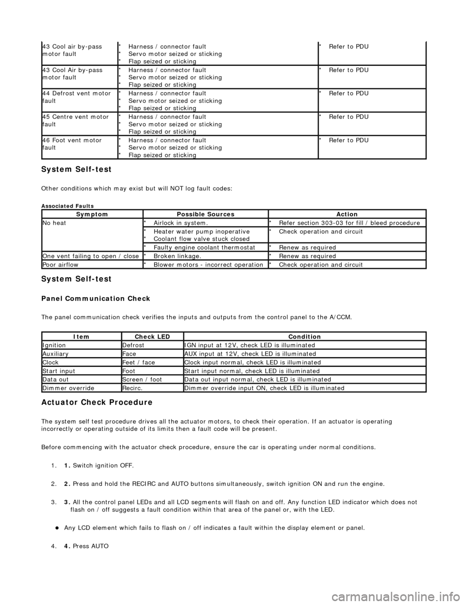
System Self-test
Other conditions which may exist but will NOT log fault codes:
Associated Faults
System Self-test
Panel Communication Check
The panel communication check veri fies the inputs and outputs from the control panel to the A/CCM.
Actuator Check Procedure
The system self test procedure drives all the actuator moto rs, to check their operation. If an actuator is operating
incorrectly or operating outside of its limi ts then a fault code will be present.
Before commencing with the actuator check procedure, ensure the ca r is operating under normal conditions.
1. 1. Switch ignition OFF.
2. 2. Press and hold the RECIRC and AUTO buttons simult aneously, switch ignition ON and run the engine.
3. 3. All the control panel LEDs and all LCD segments will flas h on and off. Any function LED indicator which does not
flash on / off suggests a fault condition within that area of the panel or, with the LED.
пЃ¬Any LCD element which fails to flash on / off indicates a fault within the display element or panel.
4. 4. Press AUTO
43 Cool air by-pass
motor faultHarness / connector fault
Servo motor seized or sticking
Flap seized or sticking
*
*
*Refer to PDU
*
43 Cool Air by-pass
motor faultHarness / connector fault
Servo motor seized or sticking
Flap seized or sticking
*
*
*Refer to PDU
*
44 Defrost vent motor
faultHarness / connector fault
Servo motor seized or sticking
Flap seized or sticking
*
*
*Refer to PDU
*
45 Centre vent motor
faultHarness / connector fault
Servo motor seized or sticking
Flap seized or sticking
*
*
*Refer to PDU
*
46 Foot vent motor
faultHarness / connector fault
Servo motor seized or sticking
Flap seized or sticking
*
*
*Refer to PDU
*
SymptomPossible SourcesAction
No heatAirlock in system.
*Refer section 303-03 for fill / bleed procedure
*
Heater water pump inoperative
Coolant flow valve stuck closed
*
*Check operation and circuit
*
Faulty engine coolant thermostat
*Renew as required
*
One vent failing to open / closeBroken linkage.
*Renew as required
*
Poor airflowBlower motors - incorrect operation
*Check operation and circuit
*
ItemCheck LEDCondition
IgnitionDefrostIGN input at 12V, check LED is illuminated
AuxiliaryFaceAUX input at 12V, check LED is illuminated
ClockFeet / faceClock input normal, check LED is illuminated
Start inputFootStart input normal, check LED is illuminated
Data outScreen / footData out input normal, check LED is illuminated
Dimmer overrideRecirc.Dimmer override input ON, check LED is illuminated
Page 1840 of 2490

Control Components - Air Discharge Temperature Sensor
Removal and Installation
Removal
Installation
1.
Remove heater matrix for access; refer to 82.25.10.
2. Detach sensor connector from heater / cooler assembly.
пЃ¬Disconnect connector.
3. Detach clip and sensor from evaporator.
пЃ¬Remove clip.
4. Remove sensor from heat er / cooler assembly.
пЃ¬Remove clip.
пЃ¬Lever case apart sufficient enough to withdraw sensor
through aperture.
1. Installation is a reversal of the removal procedure.
Page 1841 of 2490

Control Components - Ambient Air Temperature Sensor
Removal and Installation
Removal
Installation
1. NOTE: The ambient temperature sensor is accessed through
the bumper vane.
Detach sensor from bracket and disconnect connector.
1. Installation is a reversal of the removal procedure.
Page 1842 of 2490
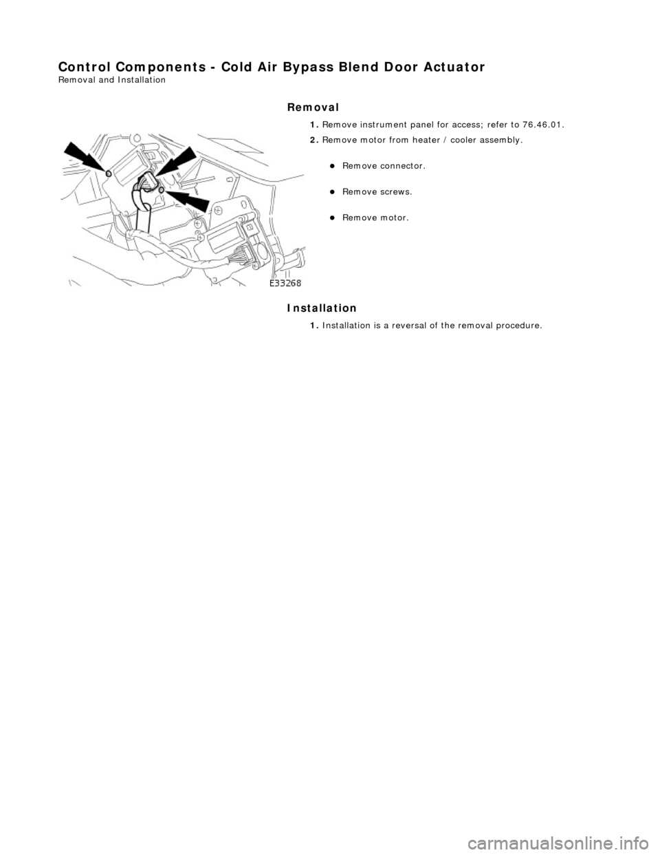
Control Components - Cold Air Bypass Blend Door Actuator
Removal and Installation
Removal
Installation
1.
Remove instrument panel for access; refer to 76.46.01.
2. Remove motor from heater / cooler assembly.
пЃ¬Remove connector.
пЃ¬Remove screws.
пЃ¬Remove motor.
1. Installation is a reversal of the removal procedure.
Page 1843 of 2490
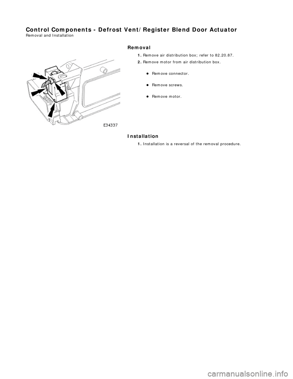
Control Components - Defrost Vent/Register Blend Door Actuator
Removal and Installation
Removal
Installation
1.
Remove air distribution box; refer to 82.20.87.
2. Remove motor from air distribution box.
пЃ¬Remove connector.
пЃ¬Remove screws.
пЃ¬Remove motor.
1. Installation is a reversal of the removal procedure.
Page 1844 of 2490
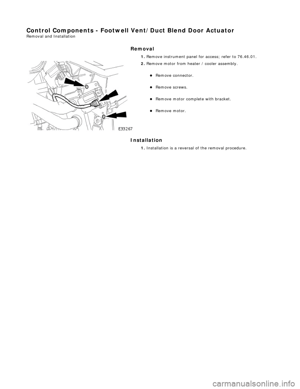
Control Components - Footwell Vent/Duct Blend Door Actuator
Removal and Installation
Removal
Installation
1.
Remove instrument panel for access; refer to 76.46.01.
2. Remove motor from heater / cooler assembly.
пЃ¬Remove connector.
пЃ¬Remove screws.
пЃ¬Remove motor complete with bracket.
пЃ¬Remove motor.
1. Installation is a reversal of the removal procedure.