battery JAGUAR X308 1998 2.G Workshop Manual
[x] Cancel search | Manufacturer: JAGUAR, Model Year: 1998, Model line: X308, Model: JAGUAR X308 1998 2.GPages: 2490, PDF Size: 69.81 MB
Page 2085 of 2490

Interior Trim and Ornamentation - Overhead Console Finish Panel
Removal and Installation
Removal
Installation
1.
Remove battery cover and disc onnect ground cable from
battery terminal. Refer to 86.15.19.
2. Remove roof console. Refer to 76.13.69.90.
3. Bend back veneer panel retain ing tangs from console and using a thin blade, carefully release panel from console.
1. Remove backing paper and apply adhesive pad to back of
panel.
2. Position and fully seat ve neer panel on console.
3. Bend retaining tangs to secure veneer panel to console.
4. Install roof console. Refer to 76.13.69.90.
5. Connect ground cable to batter y terminal and install battery
cover. Refer to 86.15.15.
Page 2089 of 2490

Interior Trim and Ornamentation - Rear Door Armrest Removal and Installation
Removal
Installation
1.
Remove battery cover and disconnect ground cable from battery
terminal. Refer to 86.15.19.
2. Remove door casing. Refer to 76.34.01.
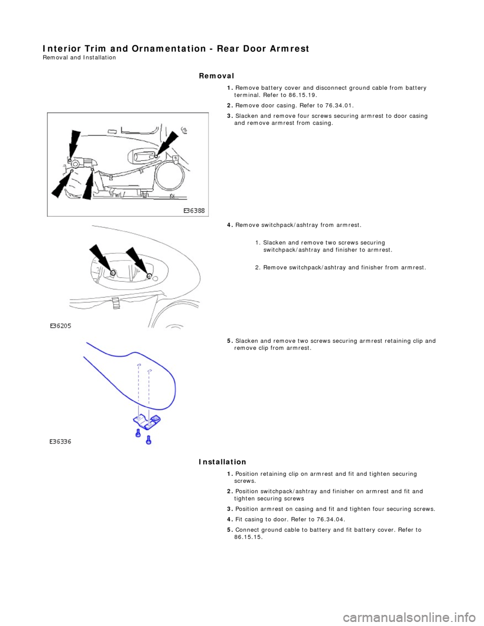
3. Slacken and remove four screws se curing armrest to door casing
and remove armrest from casing.
4. Remove switchpack/ashtray from armrest.
1. Slacken and remove two screws securing switchpack/ashtray and finisher to armrest.
2. Remove switchpack/ashtray and finisher from armrest.
5. Slacken and remove two screws secu ring armrest retaining clip and
remove clip from armrest.
1. Position retaining clip on armrest and fit and tighten securing
screws.
2. Position switchpack/ashtray and finisher on armrest and fit and
tighten securing screws
3. Position armrest on casing and fit and tighten four securing screws.
4. Fit casing to door. Refer to 76.34.04.
5. Connect ground cable to battery and fit battery cover. Refer to
86.15.15.
Page 2098 of 2490

Interior Trim and Ornamentation - Sun Visor
Removal and Installation
Removal
Installation
1.
Remove battery cover and disc onnect ground cable from
battery terminal. Refer to 86.15.19.
2. Release sun visor from suppo rt and turn downwards.
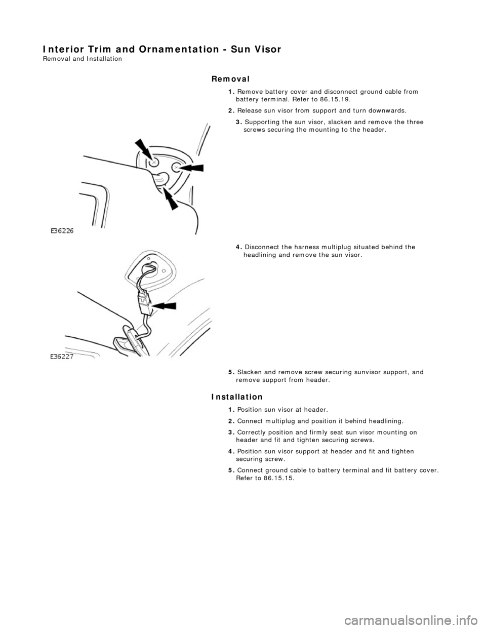
3. Supporting the sun visor, sl acken and remove the three
screws securing the mounting to the header.
4. Disconnect the harness multiplug situated behind the
headlining and remove the sun visor.
5. Slacken and remove screw securing sunvisor support, and
remove support from header.
1. Position sun visor at header.
2. Connect multiplug and position it behind headlining.
3. Correctly position and firmly seat sun visor mounting on
header and fit and tighten securing screws.
4. Position sun visor support at header and fit and tighten
securing screw.
5. Connect ground cable to battery terminal and fit battery cover.
Refer to 86.15.15.
Page 2106 of 2490

Exterior Trim and Ornamentation - Luggage Comp artment Lid Moulding
Removal and Installation
Removal
1. Remove battery cover and disc onnect ground cable from
battery terminal. Refer to 86.15.19.
2. Disconnect and remove trunk lamp assemblies. Refer to
86.45.16.
3. Remove covers from trunk latc h finisher securing bolts,
slacken and remove bolts and remove finisher.
4. Remove and discard trunk li d liner rear fasteners and
position liner for access.
5. Free trunk lid release button harness from retaining clip and
disconnect multiplug.
6. NOTE: The pressed steel fasteners fitted to Jaguar models
should be discarded on removal.
Slacken and remove nuts/fasteners securing trim finisher to
trunk lid.
Page 2108 of 2490

4.
Fit and fully seat a new harn ess grommet in trunk lid.
5. NOTE: Fit new pressed steel fasteners on Jaguar models.
Align and fully seat trim finisher on trunk lid and fit and fully
tighten securing nuts/fasteners.
6. Connect release button harness multiplug and position harness
in retaining clip.
7. Position and fully seat trunk li d trim pad and secure with new
fir tree fasteners.
8. Fit finisher over trunk latch, fi t and tighten securing bolts and
fit bolt covers..
9. Fit trunk lamp assemblies. Refer to 86.45.16.
10. Connect ground cable to batt ery terminal and fit battery
cover. Refer to 86.15.15.
Page 2119 of 2490

Rear View Mirrors - Interior Mirror Mounting Block
Removal and Installation
Removal
Installation
1. Remove battery cover and disc onnect ground cable from
battery terminal. Refer to 86.15.19.
2. Position a protective cover over top of facia.
3. Remove roof console for ac cess. Refer to 76.13.69.90.
4. Remove rain sensor unit. Refer to Section 501.16.
5. Remove mirror from mounting block. Refer to 76.10.51 or
76.10.56 (electrochromic).
6. Apply a suitable solvent around edge of mounting block.
7. Commencing at the top and exercising care to avoid windshield
damage, use a thin plastic knife to ease block free.
8. Using a suitable solvent, clean residual adhesive from block
mounting area.
1. Using masking tape, mark block mounting area on windshield.
2. Apply Permabond F Grade 5 Initiator to mounting area of
windshield.
3. Apply a bead of Permabond F246 to bottom and each vertical
side of block over 2/3 of block height.
Page 2120 of 2490

4. Press mounting block onto marked area and hold in position for one minute.
5. After a period of 15 minutes, remove and discard masking
tape.
6. Using a scraper, carefully re move any excess adhesive.
7. NOTE: The following time is the MINIMUM PERIOD required for
adhesive curing. Failure to allow th is period will result in bonding
failure, necessitating repeat of the complete procedure.
After a further period of at le ast 6 hours, install mirror on
mounting block. Refer to 76.10.51 or 76.10.56.
8. Install roof console. Refer to 76.13.69.90.
9. Install rain sensor unit. Refer to Section 501.16.
10. Remove protective cover from facia.
11. Connect ground cable to batter y terminal and install battery
cover. Refer to 86.15.15.
Page 2122 of 2490

Seating - Front Seat
Removal and Installation
Removal
1. Move the seat fully rearward and slacken and remove the
front securing bolts.
2. Move steering wheel to fully forward position.
3. Ensure that squab is fully upright, then move the seat fully
forward.
4. WARNING: FOLLOWING DISCONNECTION OF THE
BATTERY A PERIOD OF AT LEAST ONE MINUTE MUST BE
ALLOWED TO ELAPSE BEFORE WORKING ON A FRONT SEAT WITH
A SIDE AIRBAG FITTED.
Remove battery cover and disc onnect ground cable from
battery terminal. Refer to 86.15.19.
5. Remove the slider covers an d slacken and remove the two
rear securing bolts.
6. Supporting and positioning the seat for access, disconnect
multiplugs.
пЃ¬Disconnect side air bag harness multiplug.
пЃ¬Release from retaining brackets and disconnect seat
harness multiplugs.
пЃ¬Disconnect seat control module harness multiplug.
пЃ¬Cut through and remove any ti es securing harnesses to
seat frame.
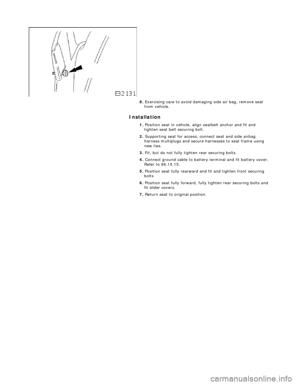
7. NOTE: Securing bolt remains captive with belt anchor.
Slacken and remove seat be lt anchor securing bolt.
Page 2123 of 2490

Installation
8. Exercising care to avoid damagi ng side air bag, remove seat
from vehicle.
1. Position seat in vehicle, align seatbelt anchor and fit and
tighten seat belt securing bolt.
2. Supporting seat for access, co nnect seat and side airbag
harness multiplugs and secure harnesses to seat frame using
new ties.
3. Fit, but do not fully tigh ten rear securing bolts.
4. Connect ground cable to battery terminal and fit battery cover.
Refer to 86.15.15.
5. Position seat fully rearward an d fit and tighten front securing
bolts
6. Position seat fully forward, full y tighten rear securing bolts and
fit slider covers.
7. Return seat to original position.
Page 2127 of 2490

Seating - Front Seat Backrest Cover
Removal and Installation
Removal
1. WARNING: FOLLOWING DISCONNECTION OF THE
BATTERY A PERIOD OF AT LEAST ONE MINUTE MUST BE
ALLOWED TO ELAPSE BEFORE WORKING ON A FRONT SEAT WITH
A SIDE AIRBAG FITTED.
Remove battery cover and disc onnect ground cable from
battery terminal. Refer to 86.15.19.
2. Remove front seat for ac cess. Refer to 76.70.01.
3. Remove Seat back finisher. Refer to 76.70.09.
4. Remove front seat headrest.
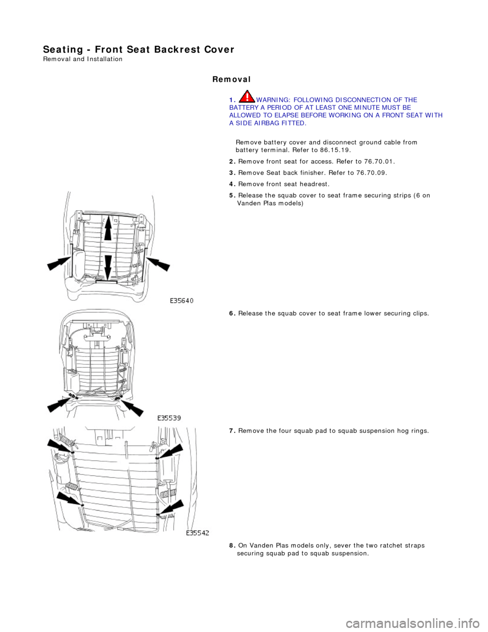
5. Release the squab cover to seat frame securing strips (6 on
Vanden Plas models)
6. Release the squab cover to seat frame lower securing clips.
7. Remove the four squab pad to squab suspension hog rings.
8. On Vanden Plas models only, sever the two ratchet straps
securing squab pad to squab suspension.