Connector JAGUAR X308 1998 2.G Workshop Manual
[x] Cancel search | Manufacturer: JAGUAR, Model Year: 1998, Model line: X308, Model: JAGUAR X308 1998 2.GPages: 2490, PDF Size: 69.81 MB
Page 2079 of 2490

Vehicles with roof opening panel
7. Install both sun visors.
For additional information, refer to: Sun Visor (501-05 Interior
Trim and Ornamentation, Re moval and Installation).
8. Install the rear window glass.
For additional information, refer to: Rear Window Glass
(501-
11 Glass, Frames and Mechanis ms, Removal and Installation).
9. Fit the electrical connectors into the retaining clips at the
overhead console location.
10. Install the overhead console.
For additional information, refer to: Overhead Console
(501-12
Instrument Panel and Console, Removal and Installation).
11. Install both C-pillar trim panels.
For additional information, refer to: C
-Pillar Trim Panel (501-05
Interior Trim and Ornamentatio n, Removal and Installation).
12. Install both A-pillar trim panels.
For additional information, refer to: A
-Pillar Trim Panel (501-05
Interior Trim and Ornamentatio n, Removal and Installation).
13. Install the roof opening panel trim.
For additional information, refer to: Roof Opening Panel Trim
(501-17 Roof Opening Panel, Removal and Installation).
Page 2100 of 2490

Exterior Trim and Ornamentation - A-Pillar Moulding LH
Removal and Installation
Removal
Installation
1.
Remove front and rear grab handles. Refer to 76.58.30
2. Remove draught welt from adjace nt section of door aperture
flange.
3. Using a trim removal tool, carefu lly ease the six trim pad fir
tree fasteners from cantrail an d upper'A' post locations.
4. If premium ICE is fitt ed, carefully withdraw trim pad for access
and disconnect tweeter connectors.
5. Remove trim pad from vehicle an d remove tweeter. Refer to
415-03.
6. Remove and discard fir tree fasteners.
1. Fit new fir tree fasten ers to the trim pad.
2. Fit tweeter to trim pad. Refer to Section 415.
3. Position trim pad for access and connect tweeter to harness.
4. Commencing at top of 'A' post and working rearwards, fully
seat three fir tree fasteners.
5. Fully seat remaining three fir tr ee fasteners in upper'A' post.
6. Fit front and rear combined gr ab handles. Refer to 76.58.30
7. Fit draught welt to adjacent section of door aperture flange.
Page 2101 of 2490

Exterior Trim and Ornamentation - A-Pillar Moulding RH
Removal and Installation
Removal
Installation
1.
Remove rear grab handle. Refer to 76.58.30.
2. Remove draught welt from adjace nt section of door aperture
flange.
3. Using a trim removal tool, carefu lly ease the six trim pad fir
tree fasteners from cantrail an d upper'A' post locations.
4. If premium ICE is fitt ed, carefully withdraw trim pad for access
and disconnect tweeter connectors.
5. Remove trim pad from vehicle an d remove tweeter. Refer to
415-03.
6. Remove and discard fir tree fasteners.
1. Fit new fir tree fasten ers to the trim pad.
2. Fit tweeter to trim pad. Refer to Section 415.
3. Position trim pad for access and connect tweeter to harness.
4. Commencing at top of 'A' post and working rearwards, fully
seat three fir tree fasteners.
5. Fully seat remaining three fir tr ee fasteners in upper'A' post.
6. Fit grab handle. Refer to 76.58.30.
7. Fit draught welt to adjacent section of door aperture flange.
Page 2116 of 2490

Rear View Mirrors - Exterior Mirror Glass
Removal and Installation
Removal
CAUTION: If as a result of accidental impact, a powered fold-back mirror is mo ved 'out of position', it must only be re-
positioned by initiating the fold-back sequence as described in this section. No attempt must be made to manually return
the mirror to the normal position. Failure to adopt this procedure will result in vibration of the unlocked mirror head and
consequent loss or distortion of rear vision.
Installation
1. Remove exterior mirror glass.
1. Motor glass to fully inward position.
2. Pressing inner edge of glass outwards, ease outer
extremity rearwards away from mirror housing.
2. Disconnect and remove mirror glass.
1. Ease glass clear of base, disconnect the two spade connectors and remove gl ass from mirror housing.
1. Fit glass to mirror housing.
пЃ¬Holding glass in position , connect the two spade
connectors.
пЃ¬Engage the mirror inner retainer on the motor lug and
press the mirror outer edge fo rward to engage the outer
retainer.
Page 2171 of 2490

Seating - Rear Seat Cushion Heater Mat
Removal and Installation
Removal
Installation
1.
Remove the rear seat cushion. Fo r additional information, refer
to the procedure in this section: Rear Seat Cushion
.
2. Remove the seat cushion cover.
3. Detach the seat cushion heater element electrical connectors.
4. Remove the seat cushion heater element.
1. To install, reverse the removal procedure.
Page 2205 of 2490

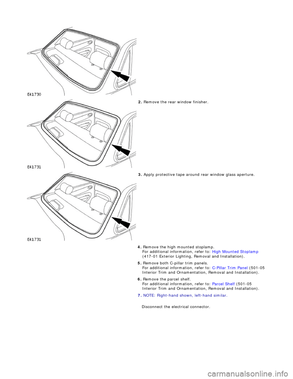
2. Remove the rear window finisher.
3. Apply protective tape around rear window glass aperture.
4. Remove the high mounted stoplamp.
For additional information, refer to: High Mounted Stoplamp
(417-01 Exterior Lighting, Removal and Installation).
5. Remove both C-pill ar trim panels.
For additional information, refer to: C
-Pillar Trim Panel (501-05
Interior Trim and Ornamentatio n, Removal and Installation).
6. Remove the parcel shelf.
For additional information, refer to: Parcel Shelf
(501-05
Interior Trim and Ornamentatio n, Removal and Installation).
7. NOTE: Right-hand shown, left-hand similar.
Disconnect the electrical connector.
Page 2206 of 2490

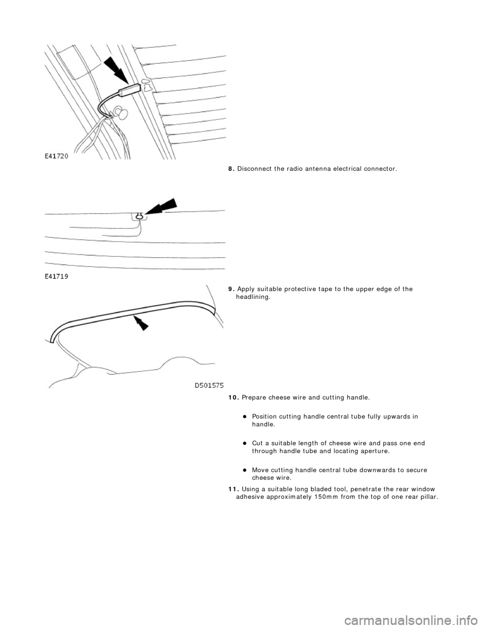
8. Disconnect the radio antenn a electrical connector.
9. Apply suitable protec tive tape to the upper edge of the
headlining.
10. Prepare cheese wire and cutting handle.
пЃ¬Position cutting handle cent ral tube fully upwards in
handle.
пЃ¬Cut a suitable length of ch eese wire and pass one end
through handle tube and locating aperture.
пЃ¬Move cutting handle central tube downwards to secure
cheese wire.
11. Using a suitable long bladed tool, penetrate the rear window
adhesive approximately 150mm fro m the top of one rear pillar.
Page 2210 of 2490

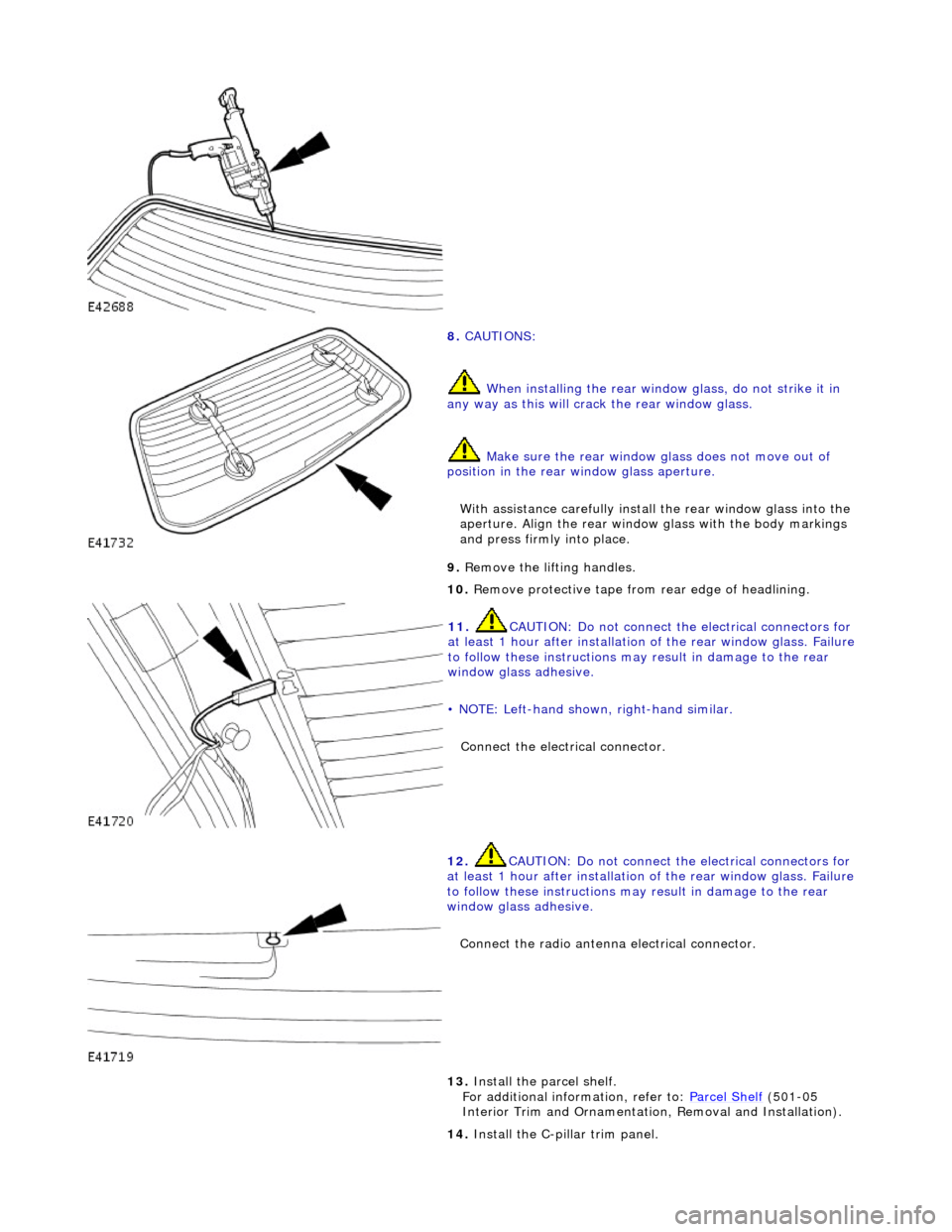
8. CAUTIONS:
When installing the rear window glass, do not strike it in
any way as this will crac k the rear window glass.
Make sure the rear window glass does not move out of
position in the rear window glass aperture.
With assistance carefully install the rear window glass into the
aperture. Align the rear window glass with the body markings
and press firmly into place.
9. Remove the lifting handles.
10. Remove protective tape from rear edge of headlining.
11. CAUTION: Do not connect the electrical connectors for
at least 1 hour after installation of the rear window glass. Failure
to follow these instructions may result in damage to the rear
window glass adhesive.
• NOTE: Left-hand shown, right-hand similar.
Connect the electrical connector.
12. CAUTION: Do not connect the electrical connectors for
at least 1 hour after installation of the rear window glass. Failure
to follow these instructions may result in damage to the rear
window glass adhesive.
Connect the radio antenna electrical connector.
13. Install the parcel shelf.
For additional information, refer to: Parcel Shelf (501-05
Interior Trim and Ornamentatio n, Removal and Installation).
14. Install the C-pillar trim panel.
Page 2235 of 2490

Instrument Panel and Console - Glove Compartment
Removal and Installation
Removal
Installation
1.
Open glovebox.
2. Supporting the glovebox, slac ken and remove the four top
securing screws.
3. Slacken and remove the two glovebox lower outer securing
screws.
4. Withdraw glovebox for access and disconnect the two
illumination harness connectors.
5. Remove glovebox from vehicle.
1. Position glovebox for access and connect illumination harness.
2. Position and fully seat glovebox.
3. Fit but do not tighten the lower securing screws.
4. Fit and fully tighten the upper securing screws.
5. Close glovebox lid.
6. Fully tighten the lower securing screws.
Page 2275 of 2490

Handles, Locks, Latches and Entry Systems - Door Lock Control Switch
Removal and Installation
Removal
1. Disconnect battery ground cable; refer to 86.15.19.
2. Remove center console veneer panel; refer to 76.47.26.
3. Displace radio for access; refer to 86.50.03.
4. Disconnect air conditioning control module flying lead
connector (blue) from harness connector located at side of 'J'
gate.
5. Displace air conditioning switch module / center console
switch module assembly.
пЃ¬Remove screw.
пЃ¬Reposition assembly for access to connector.
6. Remove air conditioning switch module / center console switch
module assembly.
пЃ¬Disconnect center console switch module harness
connector.
пЃ¬Remove assembly.