Connector JAGUAR X308 1998 2.G Workshop Manual
[x] Cancel search | Manufacturer: JAGUAR, Model Year: 1998, Model line: X308, Model: JAGUAR X308 1998 2.GPages: 2490, PDF Size: 69.81 MB
Page 2428 of 2490

пЃ¬Disconnect harness connector from transducer.
пЃ¬Remove harness from suspension assembly.
43. Remove steering rack from crossbeam.
1. Remove steering rack securing bolts.
2. Remove steering rack and mounting brackets.
44. Release stabilizer bar from link arms.
пЃ¬Remove link arm to stabil izer bar securing nut.
пЃ¬Release link arm from stabilizer bar.
пЃ¬Repeat procedure to release opposite end of stabilizer bar
from link arm.
45. Remove stabilizer bar from crossbeam.
пЃ¬Remove stabilizer bar securing bolts.
пЃ¬Remove stabilizer bar mountin g brackets and remove bar
from crossbeam.
46. Remove wishbone securing nuts.
1. Remove lower wishbone front arm eccentric bolt
securing nut.
2. Remove lower wishbone rear arm eccentric bolt
securing nut.
Page 2432 of 2490

10. With assistance position crossbeam/suspension assembly on
jack with protective wood under.
11. Traverse assembly into position below vehicle.
12. Ensure steering harn ess connector is positioned to avoid
damage during crossbeam lift .
13. NOTE: It may be necessary to use a hammer and drift to
finally align new mounting with body location.
Carefully raise crossbeam assembly into position.
пЃ¬Ensure that dowels of both crossbeam mountings are
correctly seated in body locations.
14. Ensure that both engine hydram ounts are correctly seated in
crossbeam locations.
15. Install crossbeam rear mountings.
пЃ¬Align rear mounting rubber with body location.
пЃ¬Install rear mounting securing bolt and nut and tighten
nut to 131-185 Nm.
пЃ¬Repeat procedure to install opposite side rear mounting
bolt and nut.
16. From engine compartment, install but do not tighten
crossbeam front RH bolts.
Page 2435 of 2490

26. Install power steering pi pes on pinion housing.
пЃ¬Remove blanks and install new 'O'-ring seals in pipe
connectors.
пЃ¬Apply power steering fluid to 'O' ring seals.
пЃ¬Remove blanking plugs from pinion housing ports.
пЃ¬Position pipes on pinion ports and seat 'O' rings.
27. Secure pipes to pinion housing.
пЃ¬Ensure pipes and retaining pl ate are correctly seated.
пЃ¬Install bolt and tighten to 9-12Nm.
28. Secure return pipe on steering rack.
1. Position pipe rubber support on steering rack.
2. Position pipe on support .
3. RHD vehicles. Position harness on pipe support rubber.
4. Secure pipe and harness to support with new tiestrap.
29. RHD vehicles. Using new tiestrap, secure harness to steering
rack.
Page 2436 of 2490

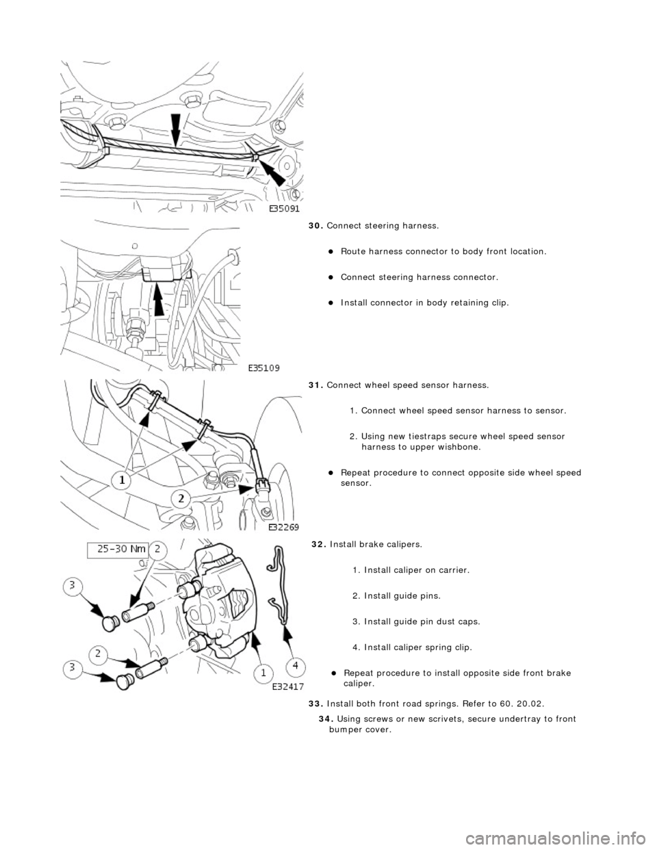
30. Connect steering harness.
пЃ¬Route harness connector to body front location.
пЃ¬Connect steering ha rness connector.
пЃ¬Install connector in body retaining clip.
31. Connect wheel speed sensor harness.
1. Connect wheel speed sensor harness to sensor.
2. Using new tiestraps secure wheel speed sensor harness to upper wishbone.
пЃ¬Repeat procedure to connect opposite side wheel speed
sensor.
32. Install brake calipers.
1. Install caliper on carrier.
2. Install guide pins.
3. Install guide pin dust caps.
4. Install caliper spring clip.
пЃ¬Repeat procedure to install opposite side front brake
caliper.
33. Install both front road sp rings. Refer to 60. 20.02.
34. Using screws or new scrivets , secure undertray to front
bumper cover.
Page 2442 of 2490

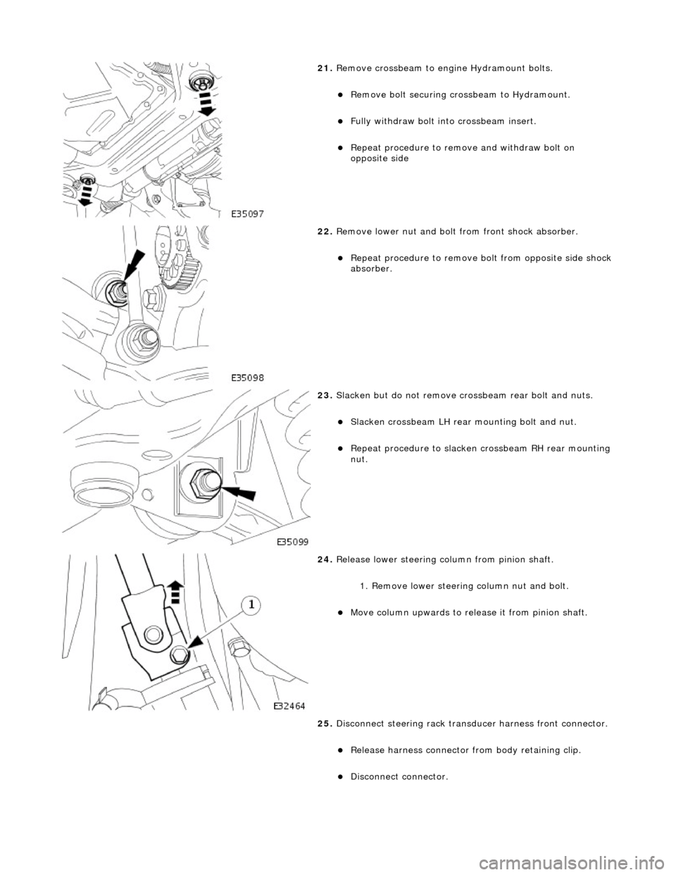
21. Remove crossbeam to engi ne Hydramount bolts.
пЃ¬Remove bolt securing crossbeam to Hydramount.
пЃ¬Fully withdraw bolt into crossbeam insert.
пЃ¬Repeat procedure to remove and withdraw bolt on
opposite side
22. Remove lower nut and bolt from front shock absorber.
пЃ¬Repeat procedure to remove bo lt from opposite side shock
absorber.
23. Slacken but do not remove crossbeam rear bolt and nuts.
пЃ¬Slacken crossbeam LH rear mounting bolt and nut.
пЃ¬Repeat procedure to slacken crossbeam RH rear mounting
nut.
24. Release lower steering column from pinion shaft.
1. Remove lower steering column nut and bolt.
пЃ¬Move column upwards to release it from pinion shaft.
25. Disconnect steering rack transducer harness front connector.
пЃ¬Release harness connector from body retaining clip.
пЃ¬Disconnect connector.
Page 2447 of 2490

3. Remove special tool 303-021 from fender channel.
11. Install crossbeam to engine Hydramount bolts.
пЃ¬Install bolt securing Hydramou nt to crossbeam and tighten to 34-46Nm.
пЃ¬Repeat procedure to install crossbeam opposite side bolt.
12. Tighten rear mounting bolt and nut to 131-185 Nm.
пЃ¬Repeat procedure to tighten opposite side rear mounting
bolt and nut.
13. Connect steering rack transducer harness front connector.
пЃ¬Connect steering ha rness connector.
пЃ¬Install harness connector on body retaining clip.
14. Slacken adjuster nut and remove camber tie down tool 204-
114 from suspension.
пЃ¬Repeat procedure to remove tie down tool from opposite
side.
Page 2453 of 2490

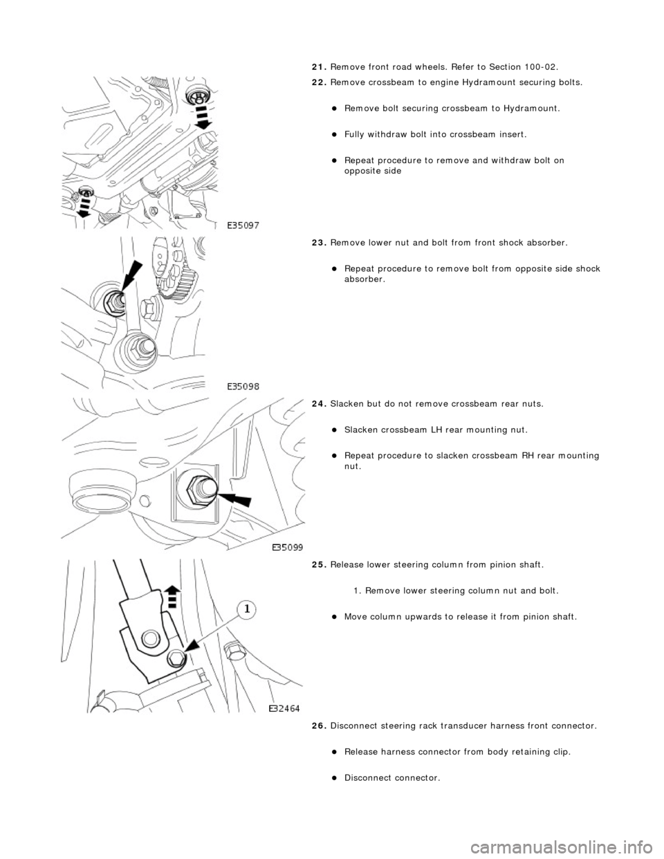
21. Remove front road wheels. Refer to Section 100-02.
22. Remove crossbeam to engine Hydramount securing bolts.
пЃ¬Remove bolt securing crossbeam to Hydramount.
пЃ¬Fully withdraw bolt into crossbeam insert.
пЃ¬Repeat procedure to remove and withdraw bolt on
opposite side
23. Remove lower nut and bolt from front shock absorber.
пЃ¬Repeat procedure to remove bo lt from opposite side shock
absorber.
24. Slacken but do not remove crossbeam rear nuts.
пЃ¬Slacken crossbeam LH rear mounting nut.
пЃ¬Repeat procedure to slacken crossbeam RH rear mounting
nut.
25. Release lower steering column from pinion shaft.
1. Remove lower steering column nut and bolt.
пЃ¬Move column upwards to release it from pinion shaft.
26. Disconnect steering rack transducer harness front connector.
пЃ¬Release harness connector from body retaining clip.
пЃ¬Disconnect connector.
Page 2458 of 2490

3. Remove special tool 303-021 from fender channel.
11. Install crossbeam to engine Hydramount bolts.
пЃ¬Install bolt securing Hydramou nt to crossbeam and tighten to 34-46Nm.
пЃ¬Repeat procedure to install crossbeam opposite side bolt.
12. Tighten rear mounting bolt and nut to 131-185 Nm.
пЃ¬Repeat procedure to tighten opposite side rear mounting
bolt and nut.
13. Connect steering rack transducer harness front connector.
пЃ¬Connect steering ha rness connector.
пЃ¬Install harness connector on body retaining clip.
14. Slacken adjuster nut and remove camber tie down tool 204-
114 from suspension.
пЃ¬Repeat procedure to remove tie down tool from opposite
side.
Page 2463 of 2490

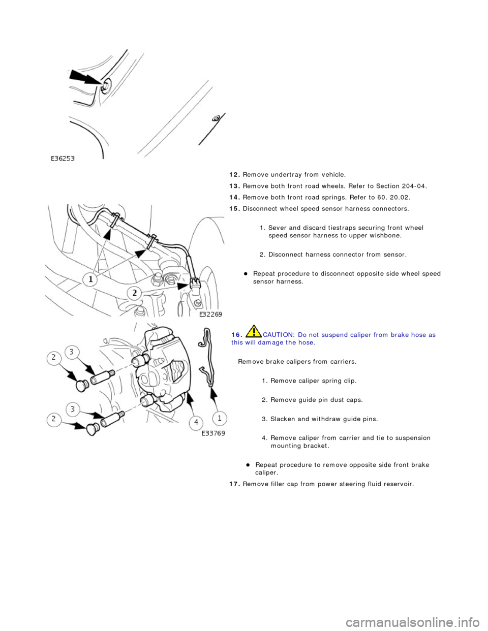
12. Remove undertray from vehicle.
13. Remove both front road wheels. Refer to Section 204-04.
14. Remove both front road springs. Refer to 60. 20.02.
15. Disconnect wheel speed sensor harness connectors.
1. Sever and discard tiestr aps securing front wheel
speed sensor harness to upper wishbone.
2. Disconnect harness connector from sensor.
пЃ¬Repeat procedure to disconnect opposite side wheel speed
sensor harness.
16. CAUTION: Do not suspend caliper from brake hose as
this will damage the hose.
Remove brake calipers from carriers.
1. Remove caliper spring clip.
2. Remove guide pin dust caps.
3. Slacken and withdraw guide pins.
4. Remove caliper from carrier and tie to suspension mounting bracket.
пЃ¬Repeat procedure to remove opposite side front brake
caliper.
17. Remove filler cap from power steering fluid reservoir.
Page 2464 of 2490

18. Disconnect steering rack transducer harness front connector.
пЃ¬Release harness connector from body retaining clip.
пЃ¬Disconnect connector.
19. Sever and discard tiestrap secu ring return pipe, harness (RHD only) and rubber support to steering rack.
20. RHD vehicles. Sever and discard tiestrap securing harness to
steering rack.
21. Route harness from behind steering return pipe.
22. Position a drain receptacle below pinion housing.
23. Remove pipe retaining plate secu ring bolt and withdraw plate.