JAGUAR X308 1998 2.G Workshop Manual
X308 1998 2.G
JAGUAR
JAGUAR
https://www.carmanualsonline.info/img/21/7640/w960_7640-0.png
JAGUAR X308 1998 2.G Workshop Manual
Page 1889 of 2490
CAUTION: The engine must not be running when multiplugs are connected or disconnected.
Check that the main B+ terminal is clean and tight.
Check that the IG terminal is clean and ma king good contact; if this connection is faulty, the generator will never function
correctly.
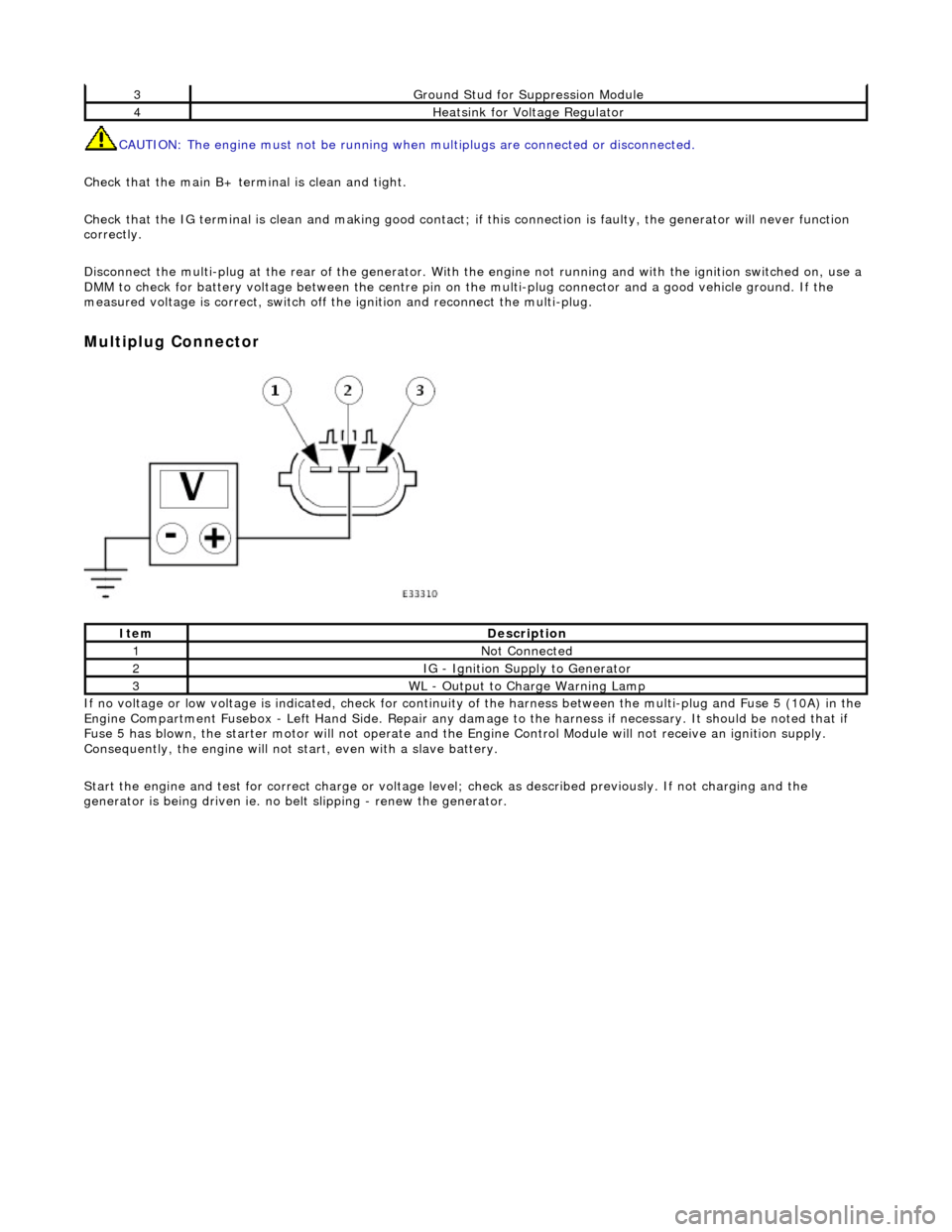
Disconnect the multi-plug at th e rear of the generator. With the engine not running and with the ignition switched on, use a
DMM to check for battery voltage between the centre pin on the multi-plug connector and a good vehicle ground. If the
measured voltage is correct, switch off the ignition and reconnect the multi-plug.
Multiplug Connector
If no voltage or low voltage is indicated, check for continuity of the harness between the multi-plug and Fuse 5 (10A) in the
Engine Compartment Fusebox - Left Hand Si de. Repair any damage to the harness if necessary. It should be noted that if
Fuse 5 has blown, the starter motor will not operate and the Engine Control Module will not receive an ignition supply.
Consequently, the engine will not st art, even with a slave battery.
Start the engine and test for correct ch arge or voltage level; check as described previously. If not charging and the
generator is being driven ie. no be lt slipping - renew the generator.
3Ground Stud for Suppression Module
4Heatsink for Voltage Regulator
ItemDescription
1Not Connected
2IG - Ignition Supply to Generator
3WL - Output to Charge Warning Lamp
Page 1916 of 2490
Speakers - Rear Door Tweeter Speaker
Removal and Installation
Removal
Installation
1.
Remove rear door casing fo r access; refer to 76.34.04.
2. Remove tweeter.
пЃ¬Disconnect connector.
пЃ¬Simultaneously depress retain ing clips and slide tweeter
away from location.
1. CAUTION: Misalignment of tw eeter during installation
could result in the retaining clips being broken. Position tweeter in
front of location and push into position.
Installation is a reversal of the removal procedure.
Page 1917 of 2490
Speakers - Subwoofer Speaker
Removal and Installation
Removal
Installation
1.
Remove rear parcel tray for access; refer to 76.67.06.90.
2. Remove rear sub-woofer speaker.
пЃ¬Remove screws.
пЃ¬Reposition speaker for access to connectors.
пЃ¬Disconnect connectors.
пЃ¬Remove speaker.
1. Installation is a reversal of the removal procedure.
Page 1923 of 2490
Exterior Lighting - Brake Pedal Position (BPP) Switch
Removal and Installation
Removal
Installation
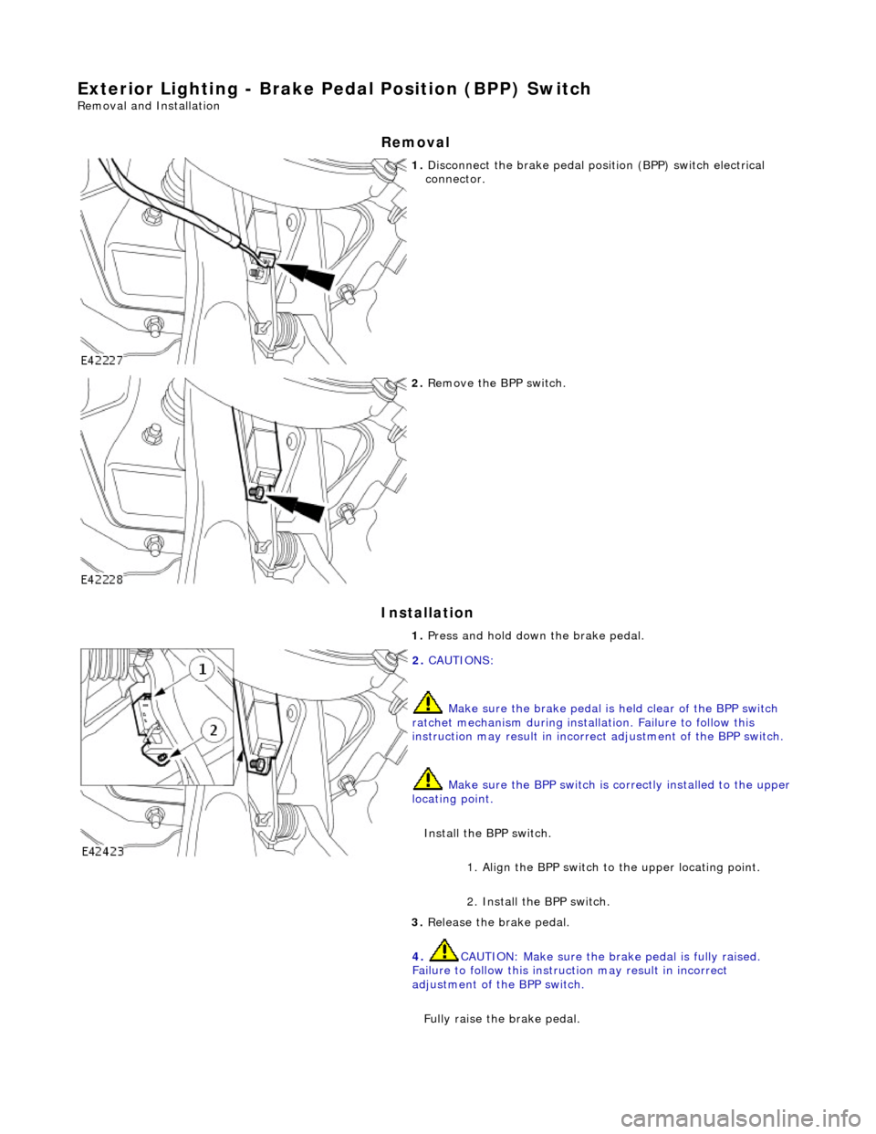
1. Disconnect the brake pedal posi tion (BPP) switch electrical
connector.
2. Remove the BPP switch.
1. Press and hold down the brake pedal.
2. CAUTIONS:
Make sure the brake pedal is held clear of the BPP switch
ratchet mechanism during installation. Failure to follow this
instruction may result in incorrect adjustment of the BPP switch.
Make sure the BPP sw itch is correctly installed to the upper
locating point.
Install the BPP switch. 1. Align the BPP switch to the upper locating point.
2. Install the BPP switch.
3. Release the brake pedal.
4. CAUTION: Make sure the br ake pedal is fully raised.
Failure to follow this instru ction may result in incorrect
adjustment of the BPP switch.
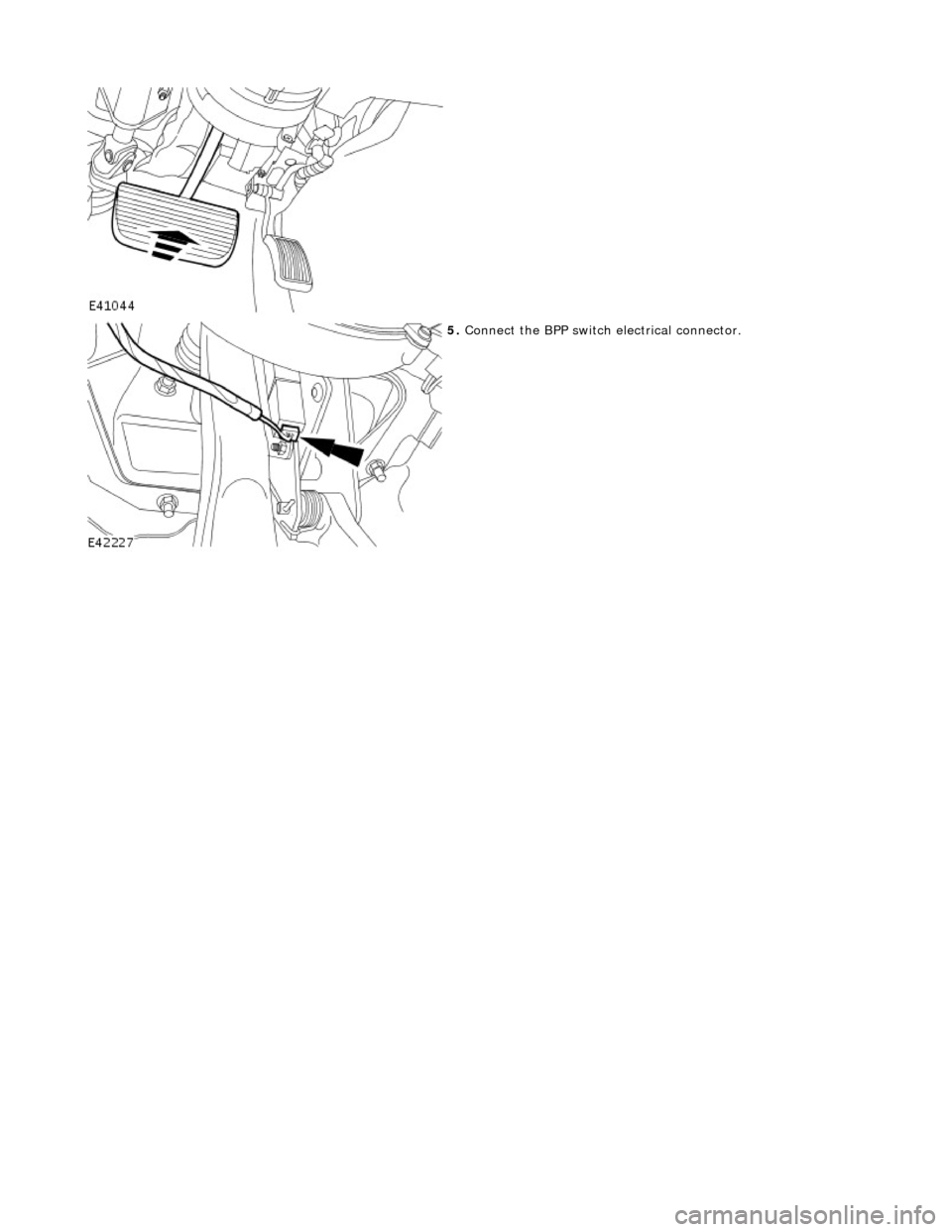
Fully raise the brake pedal.
Page 1924 of 2490
5. Connect the BPP switch electrical connector.
Page 1925 of 2490
Exterior Lighting - Fog Lamp Switch
Removal and Installation
Removal
Installation
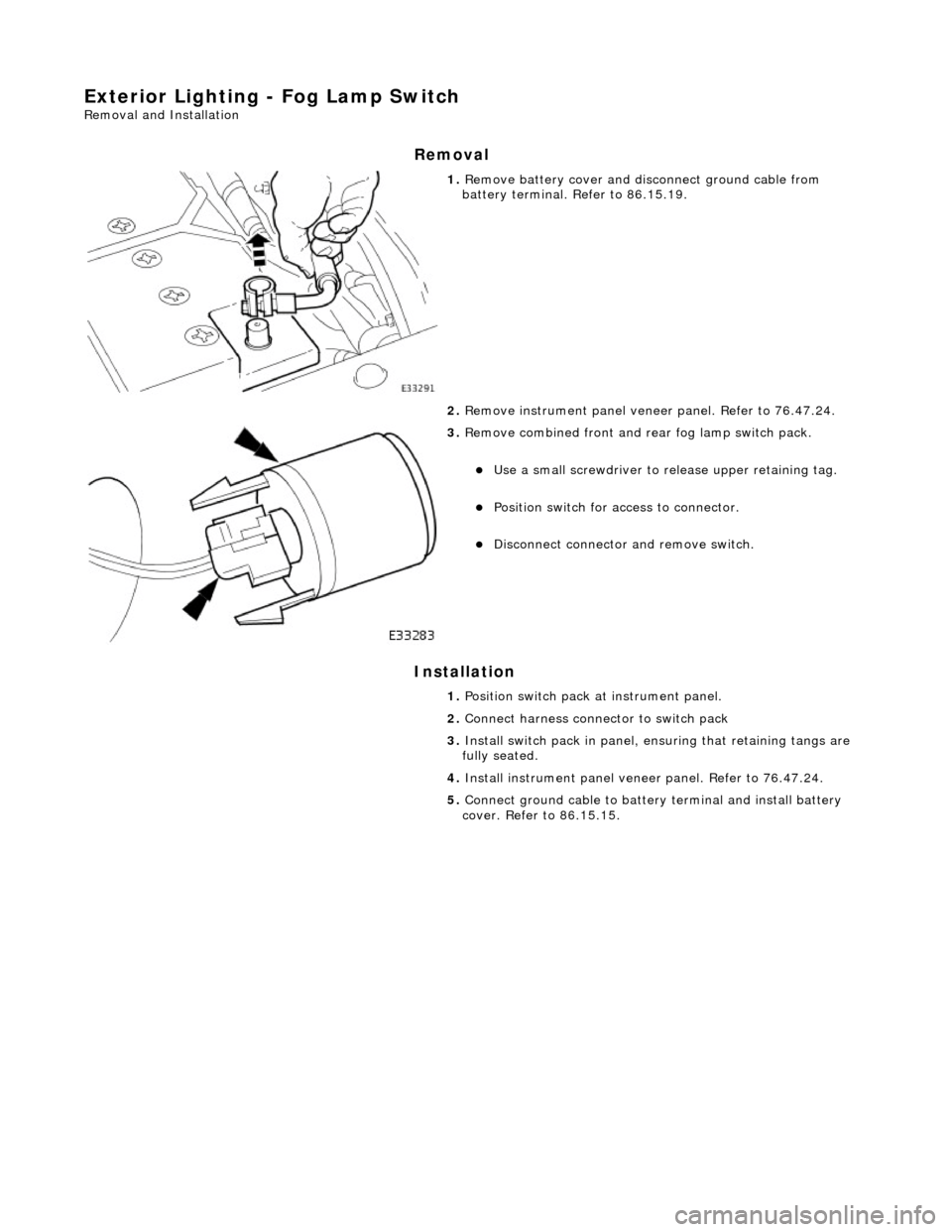
1. Remove battery cover and disc onnect ground cable from
battery terminal. Refer to 86.15.19.
2. Remove instrument pa nel veneer panel. Refer to 76.47.24.
3. Remove combined front and rear fog lamp switch pack.
пЃ¬Use a small screwdriver to re lease upper retaining tag.
пЃ¬Position switch for access to connector.
пЃ¬Disconnect connector and remove switch.
1. Position switch pack at instrument panel.
2. Connect harness connector to switch pack
3. Install switch pack in panel, ensuring that retaining tangs are
fully seated.
4. Install instrument panel veneer panel. Refer to 76.47.24.
5. Connect ground cable to batter y terminal and install battery
cover. Refer to 86.15.15.
Page 1928 of 2490
Exterior Lighting - Front Side Marker Lamp
Removal and Installation
Removal
Installation
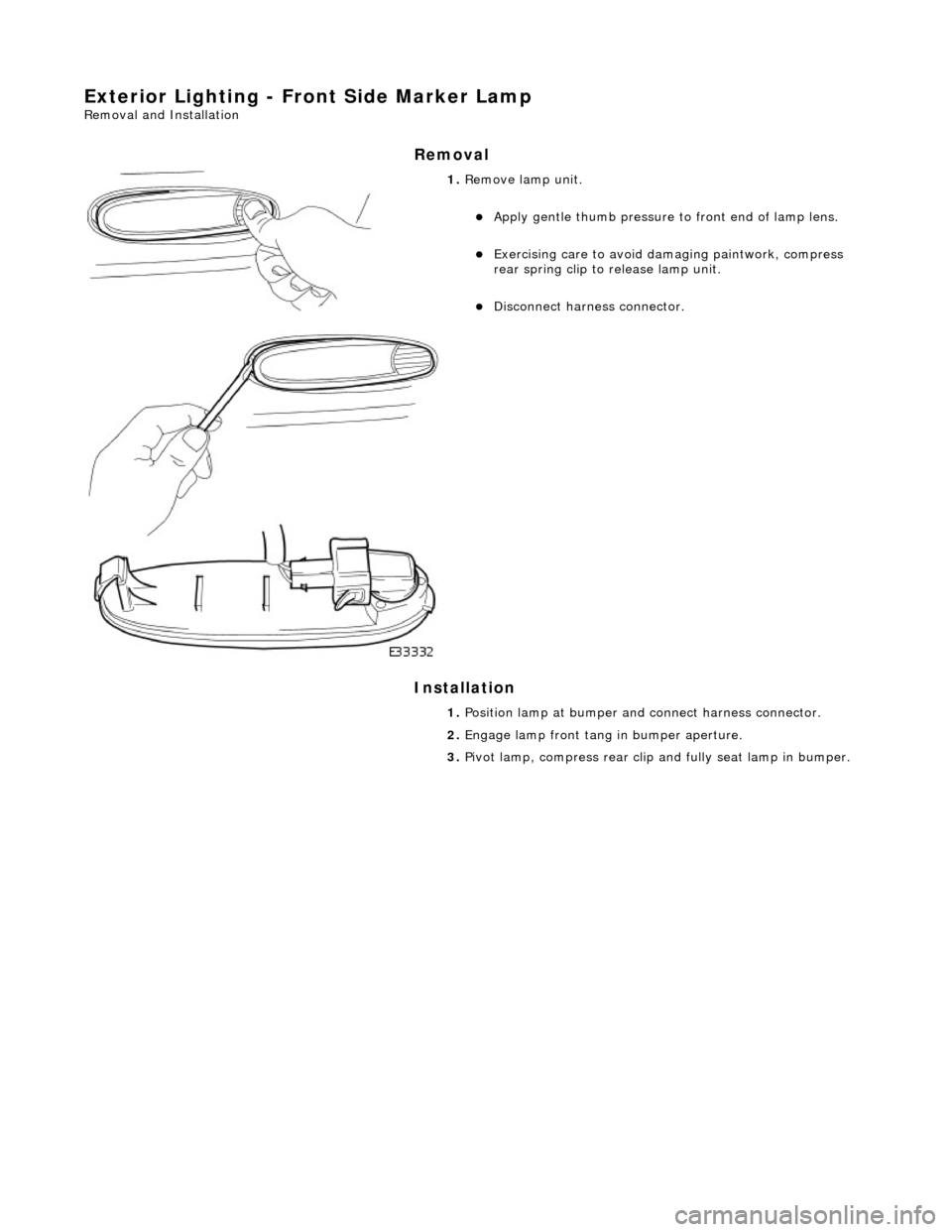
1. Remove lamp unit.
пЃ¬Apply gentle thumb pressure to front end of lamp lens.
пЃ¬Exercising care to avoid damaging paintwork, compress
rear spring clip to release lamp unit.
пЃ¬Disconnect harness connector.
1. Position lamp at bumper an d connect harness connector.
2. Engage lamp front tang in bumper aperture.
3. Pivot lamp, compress rear clip and fully seat lamp in bumper.
Page 1933 of 2490
Exterior Lighting - Headlamp Assembly
Removal and Installation
Removal
1. Remove radiator grill. Refer to 76.55.03.
2. Remove radiator grill surro und. Refer to 76.55.15.
3. Remove headlamp trim panel. Refer to 76.11.23.
4. Disconnect headlamp levelling actuator if fitted.
5. Disconnect headlamp assembly harness connector.
6. Remove headlamp assembly to body lower nuts.
7. Remove headlamp to body upper nuts.
Page 1934 of 2490
Installation
8. Remove headlamp assembly from vehicle.
1. Position headlamp assembly on body and install upper nuts.
2. Install headlamp to body lower nuts.
3. Connect headlamp assembly harness connector.
4. Connect headlamp levelling actuator harness connector if
fitted.
Page 1940 of 2490
Exterior Lighting - High Mounted Stoplamp
Removal and Installation
Removal
Installation
1. Remove lamp cover.
1. Depress two tangs at base of lamp carrier and withdraw cover.
2. Disconnect lamp harness connector.
3. Remove module.
1. Release spring clips at each end of lamp lens module and withdraw module from carrier.
4. Remove lamp carrier.
пЃ¬Release lamp carrier lower securing tangs.
пЃ¬Slide carrier upwards to release and remove carrier from
backlight.
1. Ensure that rubber insulating pads are installed on lamp
carrier.


