Connector JAGUAR X308 1998 2.G Workshop Manual
[x] Cancel search | Manufacturer: JAGUAR, Model Year: 1998, Model line: X308, Model: JAGUAR X308 1998 2.GPages: 2490, PDF Size: 69.81 MB
Page 2003 of 2490
пЃ¬WARNING: Do not use a naked flame in areas where fuel or oil have been spilt. Clean the area of residual oil
and fuel and wait un til the fuel spill has fully evaporated.
• CAUTIONS:
When using a heat source make sure that it is localised and caus es no damage to surrounding materials.
Where the repair procedure indicates that a glue lined heat shrink sleeve should be applied, apply sufficient
heat to the glue lined heat shrink to melt the glue in order to provide a water tight seal. Do not over heat the glue
lined heat shrink sleeve so that the wi ring harness insulation becomes damaged.
Using a suitable heat source, shrink the sleeve over the butt splice.
пЃ¬If further pre-terminated wiri ng harness(s) are to be installed to the sa me electrical connector, make sure that the
lead is cut at a different length to the previous joint. This makes sure that the splices will, where possible, be
staggered on the wiring ha rness and prevent a bulk of splices in one area.
пЃ¬When all of the splices have been made, fit the terminal(s) to the electrical connector, taking care that the terminals
are correctly orientated.
пЃ¬Install the wiring harness cove r and secure with adhesive electrical tape. Do not cove r the wiring harness right to the electrical connector as the terminals must have a little movement and no t be firmly bound to the electrical connector or wiring harness. Make sure that the cable identification sleeve(s) are showing at the wiring harness electrical
connector.
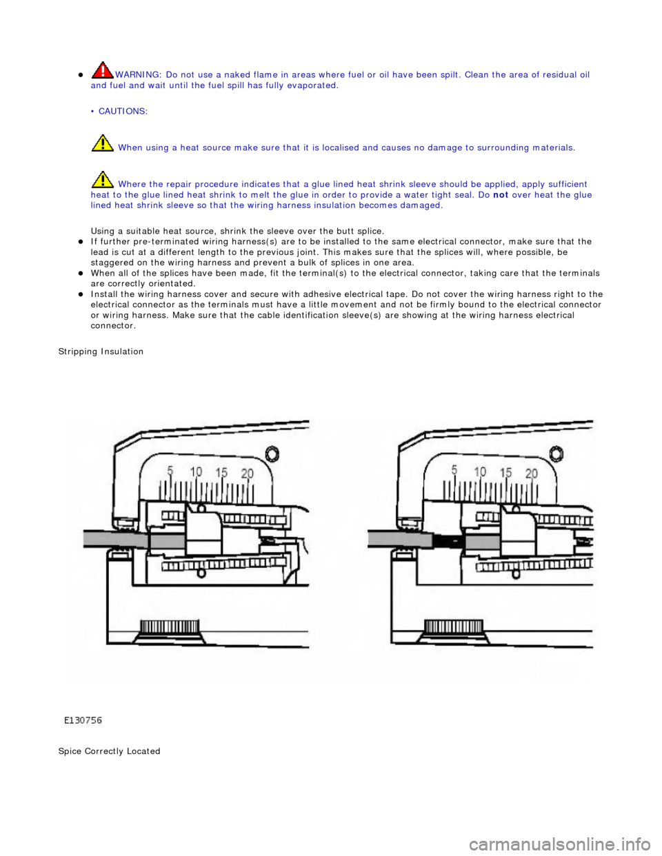
Stripping Insulation
Spice Correctly Located
Page 2014 of 2490
Multifunction Electronic Modules - Front Door Module (FDM)
Removal and Installation
Removal
Installation
1.
Disconnect battery ground cable; refer to 86.15.19.
2. Remove door casing; refer to 76.34.01.
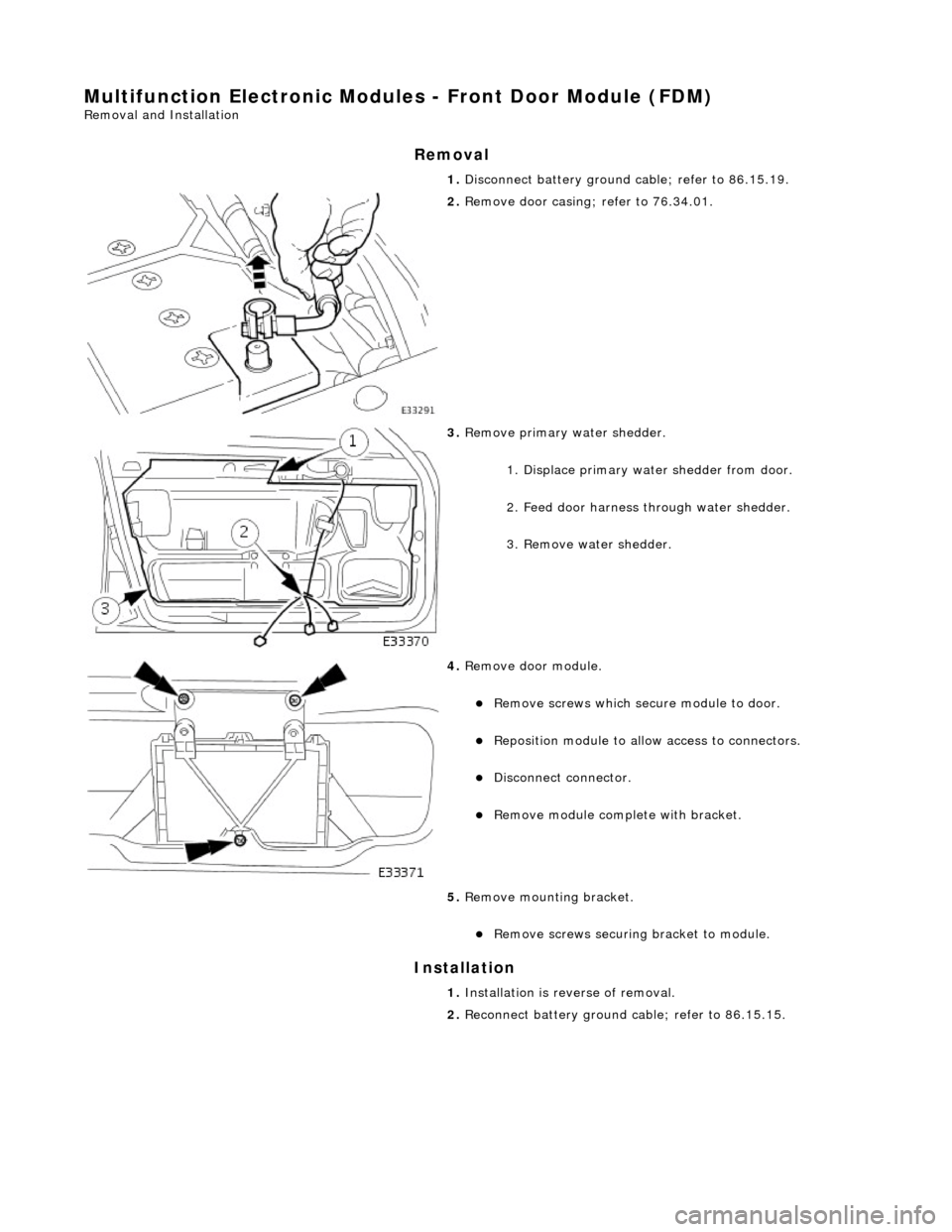
3. Remove primary water shedder.
1. Displace primary water shedder from door.
2. Feed door harness through water shedder.
3. Remove water shedder.
4. Remove door module.
пЃ¬Remove screws which secu re module to door.
пЃ¬Reposition module to allow access to connectors.
пЃ¬Disconnect connector.
пЃ¬Remove module complete with bracket.
5. Remove mounting bracket.
пЃ¬Remove screws securing bracket to module.
1. Installation is reverse of removal.
2. Reconnect battery ground cable; refer to 86.15.15.
Page 2017 of 2490
Multifunction Electronic Modules - Multifunction Electronic Module
Removal and Installation
Removal
Installation
1.
Switch ON ignition. Move pass enger seat fully rearwards.
Switch OFF ignition.
2. Disconnect battery ground cable; refer to 86.15.19.
3. Remove glove box; refer to 76.52.03.
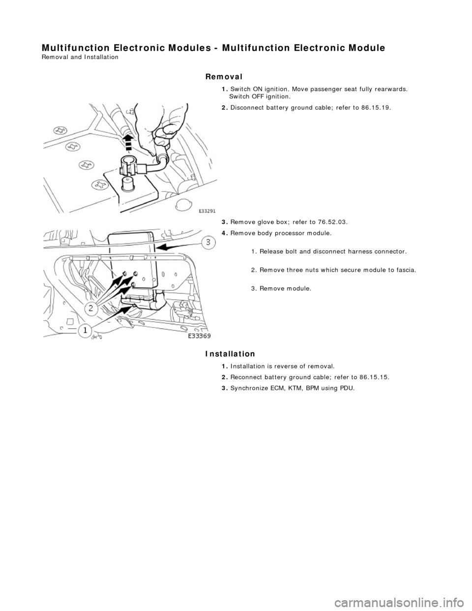
4. Remove body processor module.
1. Release bolt and discon nect harness connector.
2. Remove three nuts which secure module to fascia.
3. Remove module.
1. Installation is reverse of removal.
2. Reconnect battery ground cable; refer to 86.15.15.
3. Synchronize ECM, KTM, BPM using PDU.
Page 2018 of 2490

Multifunction Electronic Modules - Rear Door Module (RDM)
Removal and Installation
Removal
Installation
1. Disconnect battery ground cable; refer to 86.15.19.
2. Remove door casing; refer to 76.34.04.
3. Remove primary water shedder.
1. Displace primary water shedder from door.
2. Feed door harness through water shedder.
3. Remove water shedder.
4. Remove door module.
пЃ¬Remove screws which secu re module to door.
пЃ¬Reposition module to allow access to connectors.
пЃ¬Disconnect connectors.
1. Installation is reverse of removal.
2. Reconnect battery ground cable; refer to 86.15.15.
Page 2028 of 2490
Front End Body Panels - Cowl Panel Grille
Removal and Installation
Installation
1.
Open the hood and fit fender covers.
2. Remove the wiper arm and blade assembly. Refer to
84.15.44.90.
3. Slacken and remove the five pl enum cover securing screws.
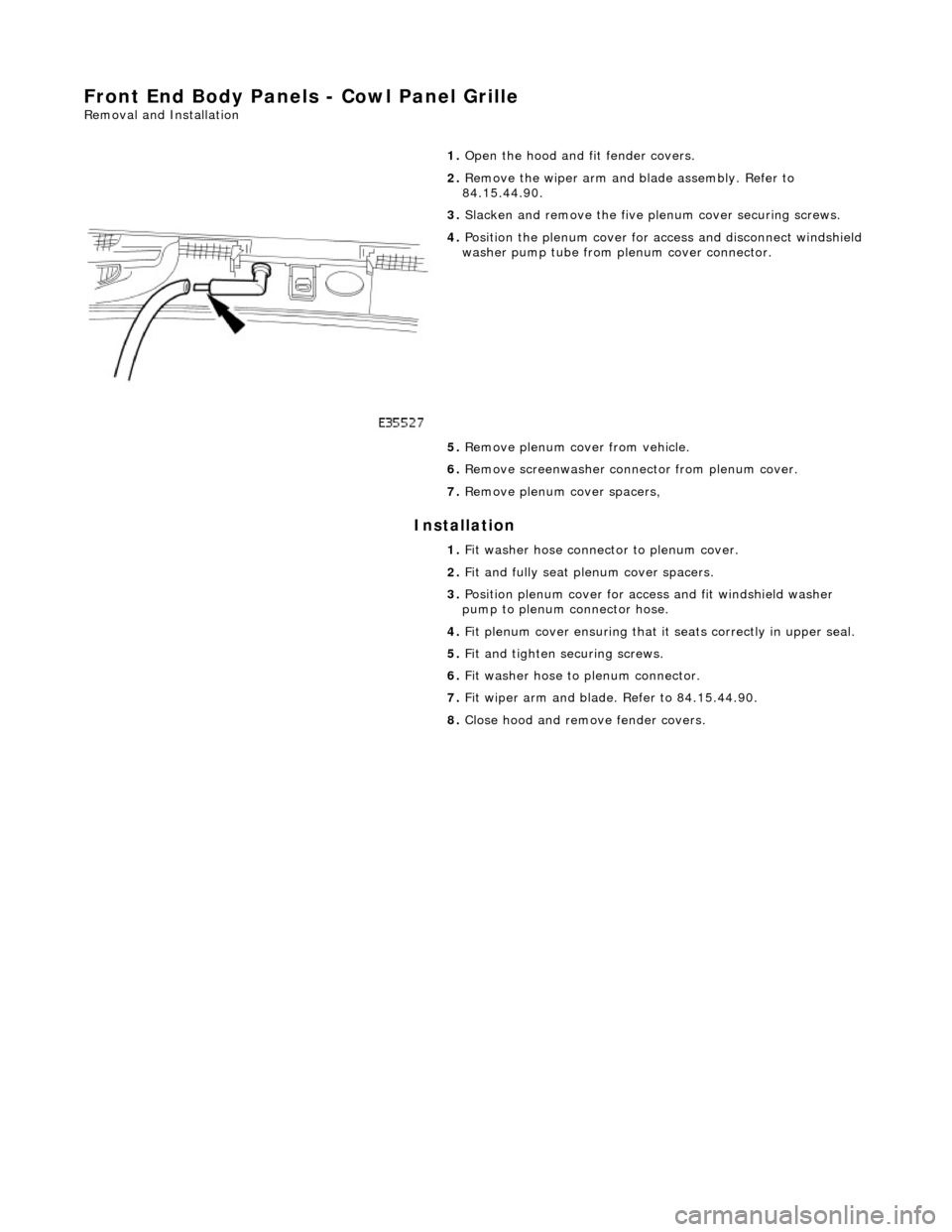
4. Position the plenum cover for access and disconnect windshield
washer pump tube from pl enum cover connector.
5. Remove plenum cover from vehicle.
6. Remove screenwasher conne ctor from plenum cover.
7. Remove plenum cover spacers,
1. Fit washer hose connector to plenum cover.
2. Fit and fully seat plenum cover spacers.
3. Position plenum cover for access and fit windshield washer
pump to plenum connector hose.
4. Fit plenum cover ensuring that it seats correctly in upper seal.
5. Fit and tighten securing screws.
6. Fit washer hose to plenum connector.
7. Fit wiper arm and blade. Refer to 84.15.44.90.
8. Close hood and remove fender covers.
Page 2034 of 2490
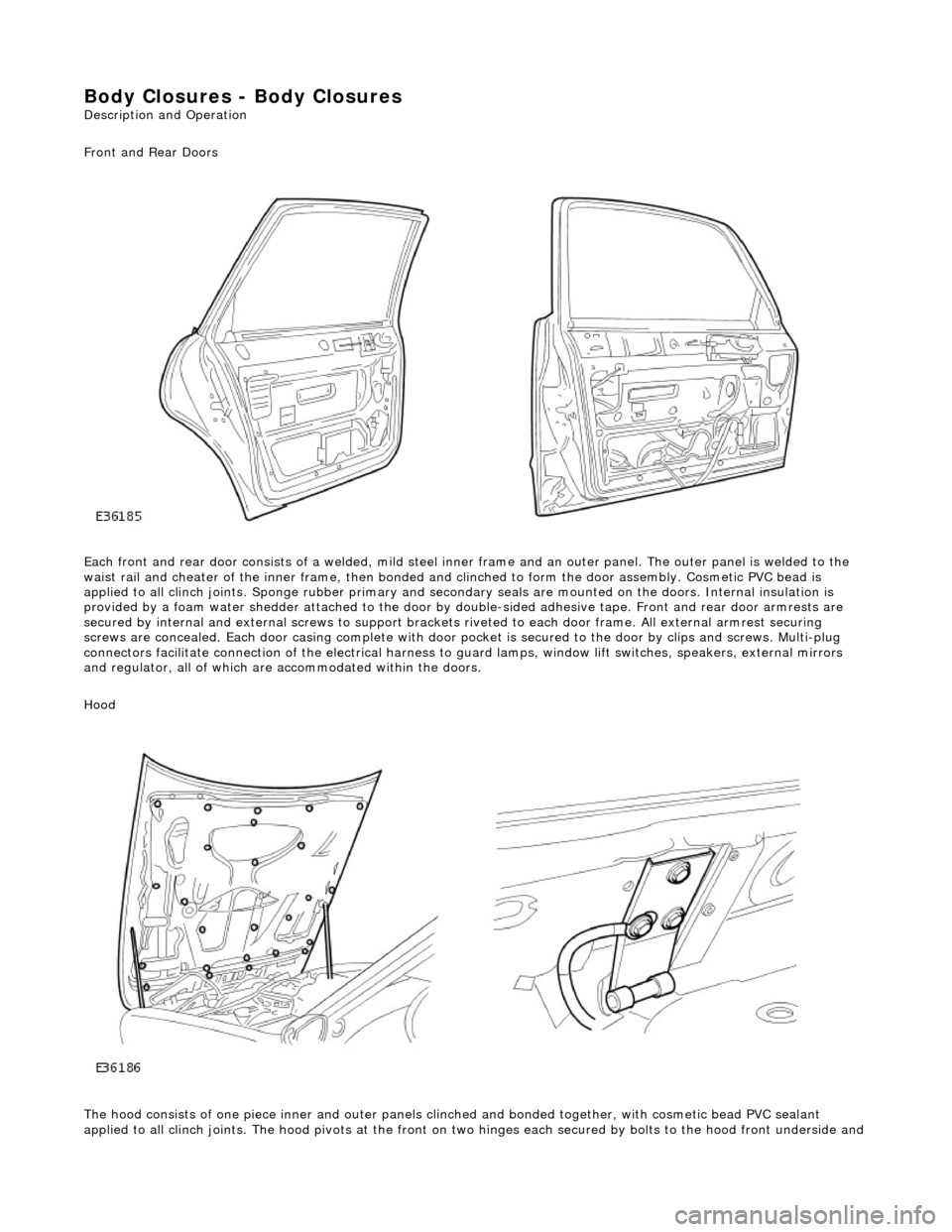
Body Closures - Body Closures
Description and Operation
Front and Rear Doors
Each front and rear door consists of a welded, mild steel inner frame and an outer panel. The outer panel is welded to the
waist rail and cheater of the inner frame, then bonded and clinched to fo rm the door assembly. Cosmetic PVC bead is
applied to all clinch joints. Sponge rubber primary and secondary seals are mo unted on the doors. Internal insulation is
provided by a foam water shedder attached to the door by double-sided adhesive tape. Front and rear door armrests are
secured by internal and external screws to support brackets riveted to each door frame . All external armrest securing
screws are concealed. Each door casing complete with door po cket is secured to the door by clips and screws. Multi-plug
connectors facilitate connection of the electrical harness to guard lamps, window lift switches, speakers, external mirrors
and regulator, all of which are accommodated within the doors.
Hood
The hood consists of one piece inner an d outer panels clinched and bonded toge ther, with cosmetic bead PVC sealant
applied to all clinch joints. The hood pivo ts at the front on two hinges each secured by bolts to the hood front underside and
Page 2059 of 2490

Interior Trim and Ornamentation - C-Pillar Trim Panel
Removal and Installation
Removal
1. Remove the passenger assist handle.
For additional information, refer to: Passenger Assist Handle
(501-05 Interior Trim and Ornamentation, Removal and
Installation).
2. Detach the rear courtesy/reading light.
3. Remove the rear courtesy/reading light.
пЃ¬Disconnect the electrical connector.
4. Detach the door aperture weatherstrip.
5. Detach the C-pillar trim panel fi r tree fasteners from the BIW.
6. Remove the C-pillar trim pa nel and discard the fir tree
fasteners.
Page 2076 of 2490

Interior Trim and Ornamentation - Headliner
Removal and Installation
Removal
Vehicles with roof opening panel
All vehicles
1. Remove the roof opening panel trim.
For additional information, refer to: Roof Opening Panel Trim
(501-17 Roof Opening Panel, Removal and Installation).
2. Remove both C-pill ar trim panels.
For additional information, refer to: C
-Pillar Trim Panel (501-05
Interior Trim and Ornamentatio n, Removal and Installation).
3. Remove both A-pill ar trim panels.
For additional information, refer to: A
-Pillar Trim Panel (501-05
Interior Trim and Ornamentatio n, Removal and Installation).
4. Remove the overhead console.
For additional information, refer to: Overhead Console
(501-12
Instrument Panel and Console, Removal and Installation).
5. Remove the rear window glass.
For additional information, refer to: Rear Window Glass
(501-
11 Glass, Frames and Mechanis ms, Removal and Installation).
6. Disconnect the anti-theft se nsors electrical connector.
7. CAUTION: With the aid of an other technician, support the
headliner to ensure it is not folded or creased during removal.
Remove both sun visors.
For additional information, refer to: Sun Visor
(501-05 Interior
Trim and Ornamentation, Re moval and Installation).
8. NOTE: Left-hand shown, right-hand similar.
Detach the retaining screw cove r from the headliner retaining
trim.
9. NOTE: Left-hand shown, right-hand similar.
Remove the headline r retaining trim.
Page 2077 of 2490

Installation
All vehicles
пЃ¬Remove the retaining screw.
10. With the aid of another tech nician, lower the headliner.
11. With the aid of another techni cian, remove the headliner.
12. NOTE: Left-hand shown, right-hand similar.
Detach the anti-theft sensors.
13. NOTE: Left-hand shown, right-hand similar.
Remove the anti-t heft sensors.
1. Disconnect the electrical connector.
1. NOTE: Left-hand shown, right-hand similar.
Page 2078 of 2490

Install the anti-theft sensors. 1. Connect the electrical connector.
2. NOTE: Left-hand shown, right-hand similar.
Attach the anti-theft sensors.
3. CAUTION: With the aid of an other technician, support the
headliner.
Install the headliner.
4. With the aid of another tech nician, raise the headliner.
5. CAUTION: Support the headliner to ensure it is not folded or creased during installation.
• NOTE: Left-hand shown, right-hand similar.
Install the headliner retaining trims.
пЃ¬Install the retaining screw.
6. NOTE: Left-hand shown, right-hand similar.
Attach the screw cover.