reservoir JAGUAR X308 1998 2.G Service Manual
[x] Cancel search | Manufacturer: JAGUAR, Model Year: 1998, Model line: X308, Model: JAGUAR X308 1998 2.GPages: 2490, PDF Size: 69.81 MB
Page 422 of 2490
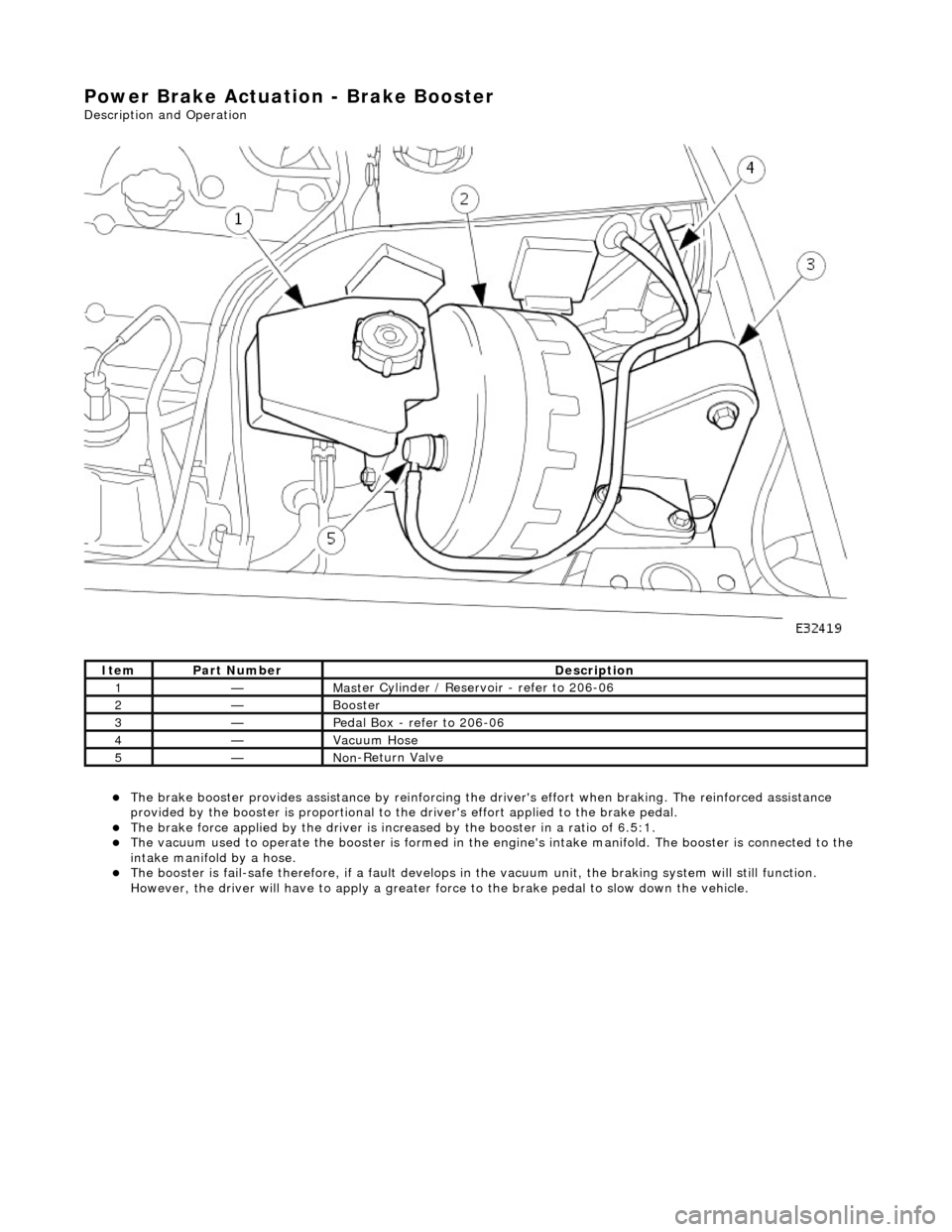
Power Brake Actuation - Brake Booster
Description and Operation
The brake b
ooster provides assi
stance by reinforcing the driver's effort when brakin g. The reinforced assistance
provided by the booster is proportional to the driver's effort applied to the brake pedal.
The brake force applied by
the driver is incr
eased by the booster in a ratio of 6.5:1.
Th
e vacuum used to operate the booster
is formed in the engine's intake manifold. The booster is connected to the
intake manifold by a hose.
The boost
er is fail-safe therefore, if a fault develops in
the vacuum unit, the braking system will still function.
However, the driver will have to apply a greater fo rce to the brake pedal to slow down the vehicle.
It e
m
Par
t
Number
De
scr
iption
1—Mas
t
er Cylinder / Reservoir - refer to 206-06
2—Booster
3—Pedal Box
- refer to 206-06
4—Vacuu
m
Hose
5—No
n
-Return Valve
Page 425 of 2490
Power Brake Actuatio
n - Brake Boos
ter and Brake Master Cylinder
Re
moval and Installation
Remov
al
• C
AUTIONS:
Replacement of nuts and bolts: Various thread-locking de vices are used on nuts and bolts throughout the vehicle.
These devices restrict the number of times a nut or bolt can be used. See section 100-00 for information.
Remove brake fluid spilla ge immediately from paint work, with clean water.
1. Position vehi
cle on a four-post lift.
2. Move driver's seat fully rearward.
3. Open engine compartment and fit paint work protection covers
to fenders.
4. Disconnect battery ground cable (IMPORTANT, see operation
86.15.19 for further information).
5. Remove engine compartment rear cover. Refer to operation
76.11.35.
6. Remove pedal housing, brake booster and master cylinder
assembly. Refer to operation 70.35.39.
7. Remove reservoir filler cap and po ur residual brake fluid into a
container. Refit cap.
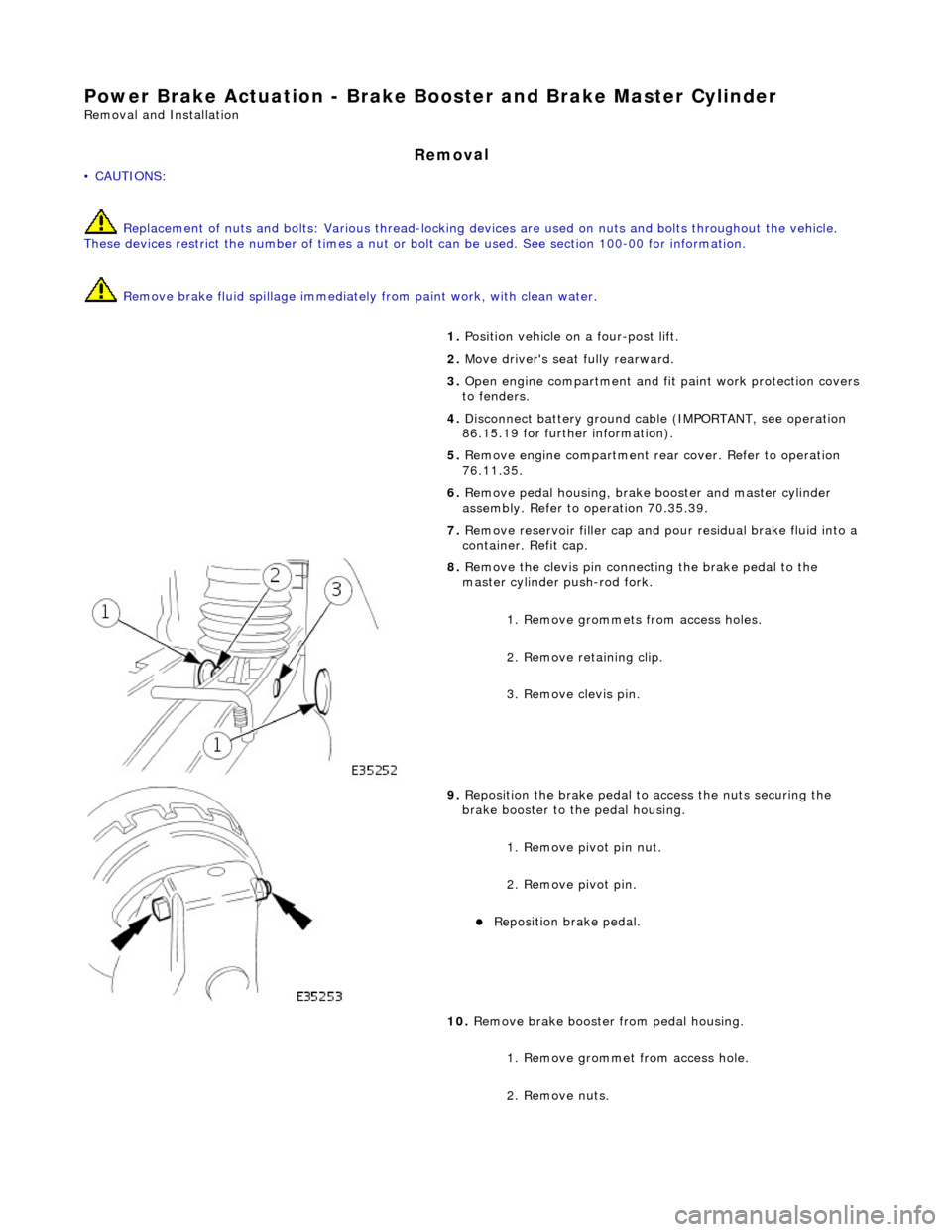
8. R
emove the clevis pin connecting the brake pedal to the
master cylinder push-rod fork.
1. Remove grommets from access holes.
2. Remove retaining clip.
3. Remove clevis pin.
9. Re
position the brake pedal to access the nuts securing the
brake booster to the pedal housing.
1. Remove pivot pin nut.
2. Remove pivot pin.
Reposition brake pedal.
10
.
Remove brake booster from pedal housing.
1. Remove grommet from access hole.
2. Remove nuts.
Page 430 of 2490
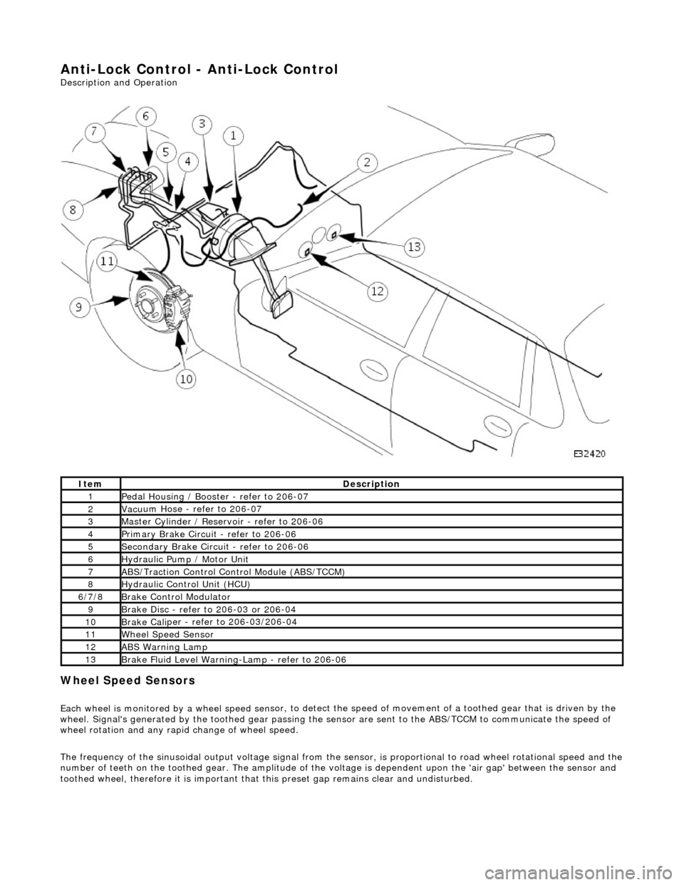
Anti-Lock Control - Anti-Lock Control
Description and Operation
Wheel Spe
ed Sensors
Each
wheel is monitored by a wheel speed se n
sor, to detect the speed of movement of
a toothed gear that is driven by the
wheel. Signal's generate d by the toothed gear passing th e sensor are sent to the ABS/TCCM to communicate the speed of
wheel rotation and any rapid change of wheel speed.
The frequency of the sinusoidal output voltag e signal from the sensor, is proportional to road wheel rotational speed and the
number of teeth on the toothed gear. The amplitude of the volt age is dependent upon the 'air gap' between the sensor and
toothed wheel, therefore it is important that this preset gap remains clear and undisturbed.
Ite
m
De
scr
iption
1Pe
dal Housi
ng / Booster - refer to 206-07
2Vac
u
um Hose - refer to 206-07
3Mas
t
er Cylinder / Reservoir - refer to 206-06
4Pri
m
ary Brake Circuit - refer to 206-06
5Sec
ondary Brake Circuit - refer to 206-06
6Hydraulic
Pump / Motor Unit
7ABS/Traction
Control Control Module (ABS/TCCM)
8Hydraulic Cont
rol Unit (HCU)
6/
7/
8
Br
ak
e Control Modulator
9Brake
Di
sc - refer to 206-03 or 206-04
10Brake
Cali
per - refer to 206-03/206-04
11Wh
ee
l Speed Sensor
12ABS Warning Lamp
13Brake
Fl
uid Level Warning-Lamp - refer to 206-06
Page 433 of 2490
clos
ed outlet valves.
Traction Control
Trac
tion control has the same capabilities as ASC but with th
e added ability to actuate the brakes of the spinning wheel.
This enhances ASC by improving acceleration particularly on surfaces with uneven friction , e.g. one wheel on ice the other
on tarmac.
When wheelspin occurs, brake line pressure to the slipping wheel is generated, to operate that wheel's brake. The BCM
achieves this by closing the cut-off solenoid valve and oper ating the hydraulic pump. Brake fluid is then drawn from the
reservoir through the non-actuated mast er cylinder to the brake caliper.
A 'TRAC' amber warning light flashes on the instrument panel when the system detects a spinning wheel.
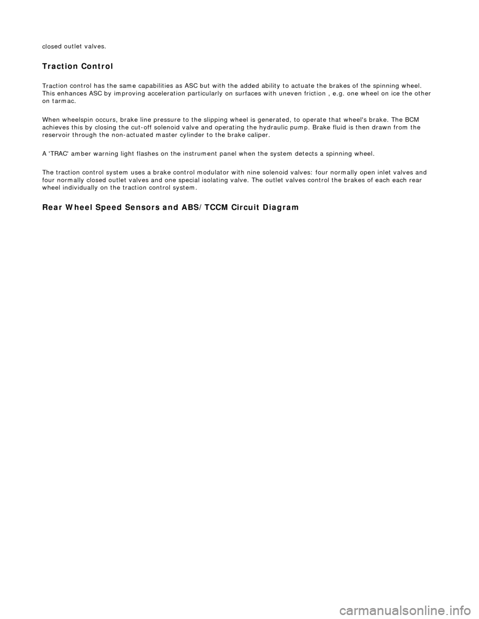
The traction control system uses a brake control modulator with nine solenoid valv es: four normally open inlet valves and
four normally closed outlet valves and one special isolating va lve. The outlet valves control the brakes of each each rear
wheel individually on the traction control system.
Rear Wheel Speed Senso
rs and ABS/TCCM Circuit Diagram
Page 458 of 2490
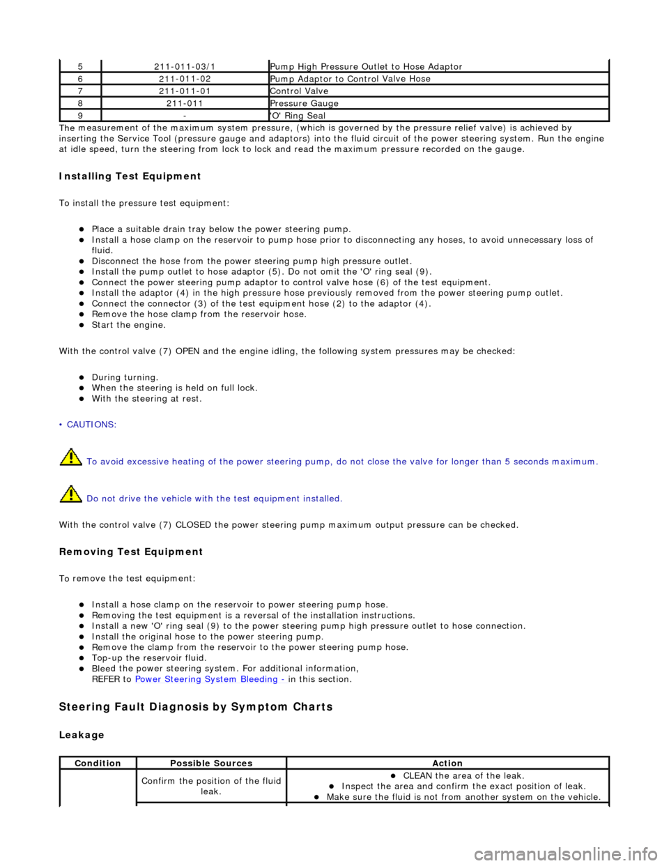
The
measurement of the maximum system pressure, (which is
governed by the pressure relief valve) is achieved by
inserting the Service Tool (pressure gauge and adaptors) into th e fluid circuit of the power steering system. Run the engine
at idle speed, turn the st eering from lock to lock and read the ma ximum pressure recorded on the gauge.
Installin
g Test Equipment
To
in
stall the pressure test equipment:
Pla
c
e a suitable drain tray be
low the power steering pump.
Install a hose clamp on
the re
servoir to pump hose prior to disconnecting any hoses, to avoid unnecessary loss of
fluid.
Disc
onnect the hose from the power st
eering pump high pressure outlet.
Install the pu
mp outlet to hose adaptor (5
). Do not omit the 'O' ring seal (9).
Connect the power steering
pump
adaptor to control valve hose (6) of the test equipment.
Install th e adaptor (4) in th
e high
pressure hose previously removed from the power steering pump outlet.
Conn
ect the connector (3) of the test equipment hose (2) to the adaptor (4).
R
e
move the hose clamp fro
m the reservoir hose.
Start th
e engine.
With the control valve (7) OPEN and the engine idli ng, the following system pressures may be checked:
Du
ring turning.
W
h
en the steering is
held on full lock.
With
the steeri
ng at rest.
• CAUTIONS:
To avoid excessive heating of the po wer steering pump, do not close the valve for longer than 5 seconds maximum.
Do not drive the vehicle with the test equipment installed.
With the control valve (7) CLOSED the power steering pump maximum ou tput pressure can be checked.
Removing Test Equipment
To
remove the test equipment:
Install a hose clamp
on
the reservoir to power steering pump hose.
Re
movi
ng the test equipmen
t is a reversal of the in stallation instructions.
Install a new '
O
' ring seal (9) to the power steering pump high pressu
re outlet to hose connection.
Instal
l the original hose to
the power steering pump.
Re
move the clamp from the reservoir to
the power steering pump hose.
Top-up the reservoir flui
d.
Ble
e
d the power steerin
g system. For additional information,
REFER to Power Steering System Bleeding
- in thi
s section.
Stee
ring Fault Diagnosis by Sympt
om Charts
Leakage
52
11-0
11-03/1
Pump High Pressure Ou
tlet
to Hose Adaptor
621
1
-011-02
Pump Adaptor
to Contro
l Valve Hose
721
1
-011-01
Control Valve
82
11-
011
Pressure Gauge
9-'O
'
Ring Seal
Cond
iti
on
Possib
l
e Sources
Acti
o
n
Co
nfirm
the position of the fluid
leak.
CLEAN th
e area of the leak.
In
s
pect the area and confirm the exact position of leak.
Make sure the fluid
is not from anoth
er system on
the vehicle.
Page 471 of 2490
Stee
ring System - General Informatio
n - Power Steering System Filling
and Bleeding
Gen
eral Procedures
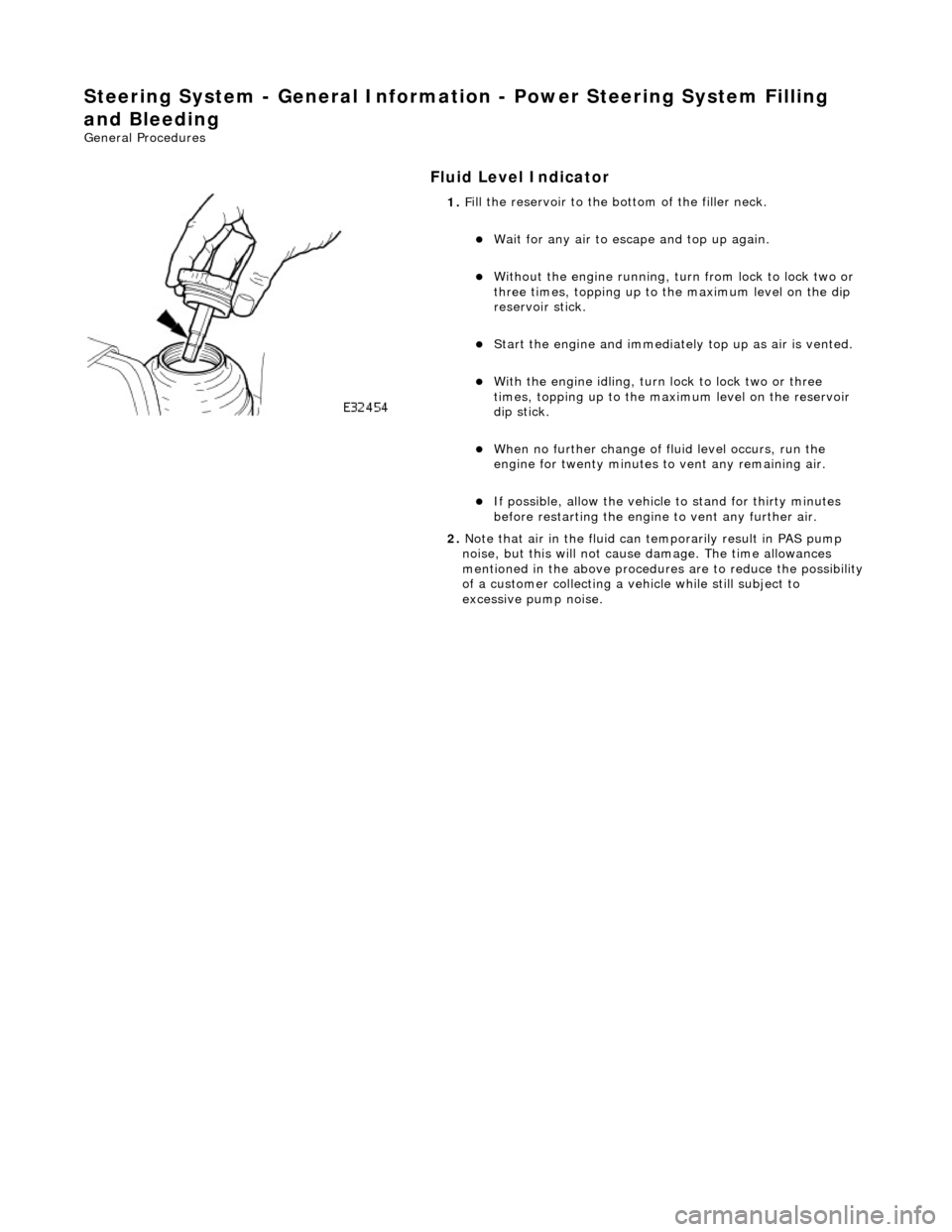
Fluid Level Indica
tor
1.
F
ill the reservoir to the bo
ttom of the filler neck.
W
ait for any air to escape and top up again.
W
ithout the engine running, tu
rn from lock to lock two or
three times, topping up to the maximum level on the dip
reservoir stick.
St
art the engine and
immediately top up as air is vented.
W
ith the engine idling, turn
lock to lock two or three
times, topping up to the ma ximum level on the reservoir
dip stick.
W
hen no further change of
fluid level occurs, run the
engine for twenty minutes to vent any remaining air.
If po
ssible, allow the vehicle
to stand for thirty minutes
before restarting the engine to vent any further air.
2. Note that air in the fluid can temporarily result in PAS pump
noise, but this will not cause damage. The time allowances
mentioned in the above procedures are to reduce the possibility
of a customer collecting a vehicle while still subject to
excessive pump noise.
Page 472 of 2490

Steering System - General Information - Power Steeri
ng System Flushing
Gen
e
ral Procedures
• NOTE: If heavy steering or contamination within the power steering system is found, it is necessary to carry out the
system flush procedure as detailed below. If any components have been replaced in the power steering system the
procedure below must be carried out in full.
• NOTE: Some variation in the illustrations may occur, but the essential information is always correct.
1. Remove the power steering fluid reservoir cap.
2. Using a suitable syringe, remove the power steering fluid from
the power steering fluid reservoir.
3. CAUTIO
N: Be prepared to
collect escaping fluids.
• NOTE: Note the orientation of the clip. Detach the power steeri ng fluid reservoir.
De
tach but do not remove the power steering fluid
reservoir.
Re lea
se the power steering fluid return hose from the
power steering fluid reservoir.
If a qui
ck release coupling is fitted to the power
steering return ho se, release the powe r steering fluid
return hose from the coupling by removing the clip.
4. CAUTIO
N: Be prepared to
collect escaping fluids.
• NOTE: Make sure that all openings are sealed. Use new
blanking caps.
Using a suitable blanking cap, cap the power steering
reservoir return pipe.
5. CAUTIO
N: Be prepared to
collect escaping fluids.
• NOTE: Make sure the extended pipe is not kinked or twisted
and is correctly secure d with hose clips.
Attach a suitable pipe to the power steering return hose to
allow the fluid to drain.
Page 473 of 2490

6. NO
TE: The suitable funnel should have the a capacity of 4
litres and O-ring seal
• NOTE: The suitable funnel must be tightly sealed to the
power steering fluid reservoi r to avoid fluid leakage.
Install a suitable funnel onto the power steering fluid
reservoir.
7. WARNING: Do not work on or under a vehicle supported
only by a jack. Always support the vehicle on safety stands.
Raise and support the vehicle with the wheels just clear of the
ground.
8. CAUTI
ONS:
Steps 8 and 9 must be carried out within 2 - 3 seconds of
each other. Failure to follow this instruction may result in damage
to the power steering system.
Be prepared to collect escaping fluids.
Using the suitable funnel, top up the power steering system
with the specified fluid. Make su re the fluid level is maintained
at two thirds full in the funnel.
9. CAUTI
ONS:
Be prepared to collect escaping fluids.
Page 474 of 2490

Do not al
low the power steering fluid level in the power
steering fluid reservoir to fall below the minimum power
steering fluid level. Fa ilure to follow this instruction may result
in damage to the po wer steering system.
Make sure the engine is swit ched off as soon as the full
4 litres of power steering flui d has entered the power steering
fluid reservoir.
Flush the power steering system.
St art
the engine
W
it
h assistance turn the stee
ring slowly lock to lock 3
times at approximately 1 revo lution every 5 seconds.
Continue
to flush the power steering system until 4
litres of power steering fl uid has been added to the
power steering reservoir. This should take
approximately 30 seconds.
10 . CAUTI
ON: Be prepared to
collect escaping fluids.
Remove the suitable funnel.
11 . CAUTI
ON: Be prepared to
collect escaping fluids.
Remove the suitable pipe to th e power steering return hose.
12. CAUTI
ON: Be prepared to
collect escaping fluids.
Page 475 of 2490
•
NOTE: Note the orientation of the clip.
If a quick release coupling is fitt ed to the power steering return
hose, connect the power steerin g fluid return hose to the
coupling by installing the clip.
13. Install a new power steering fl uid reservoir. For additional
information, refer to: (211-02) Power Steering Fluid Reservoi r - 4.2L/3.0L/2.7L Diesel
(Removal and Installation),
Power Steering Fluid Reservoir - 3.0L Diesel (Removal and
Installation).