JAGUAR X308 1998 2.G Manual PDF
X308 1998 2.G
JAGUAR
JAGUAR
https://www.carmanualsonline.info/img/21/7640/w960_7640-0.png
JAGUAR X308 1998 2.G Manual PDF
Page 2433 of 2490
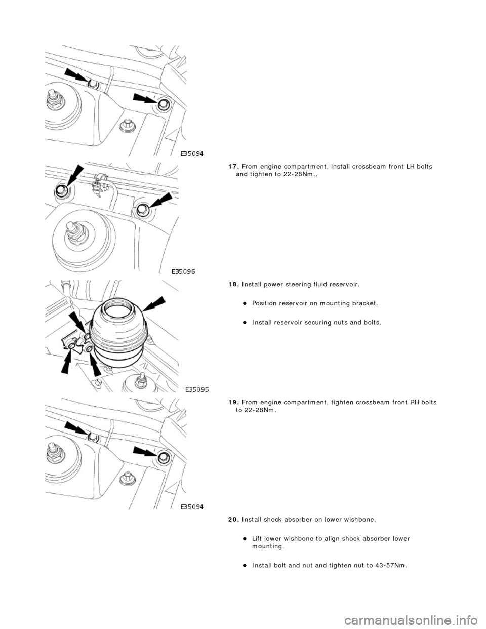
17. From engine compartment, install crossbeam front LH bolts
and tighten to 22-28Nm..
18. Install power steering fluid reservoir.
Position reservoir on mounting bracket.
Install reservoir securi ng nuts and bolts.
19. From engine compartment, tighten crossbeam front RH bolts
to 22-28Nm.
20. Install shock absorber on lower wishbone.
Lift lower wishbone to align shock absorber lower
mounting.
Install bolt and nut and ti ghten nut to 43-57Nm.
Page 2443 of 2490
26. Support weight of crossbeam.
Position a jack under crossbeam.
Place a piece of wood between jack and crossbeam.
Raise jack to just support crossbeam.
27. From engine compartment, remo ve crossbeam front RH bolts.
28. Remove power steering fl uid reservoir for access.
Remove reservoir securing nuts and bolts.
Position reservoir for access.
29. From engine compartment, remo ve crossbeam front LH bolts.
Page 2445 of 2490
correctly seated in body locations.
3. Ensure that both engine hydram ounts are correctly seated in
crossbeam locations.
4. From engine compartment, install but do not tighten
crossbeam front RH bolts.
5. From engine compartment, install crossbeam front LH bolts
and tighten to 22-28Nm.
6. Install power steering fluid reservoir.
Position reservoir on mounting bracket.
Install reservoir securi ng nuts and bolts.
Page 2454 of 2490
27. Support weight of crossbeam.
Position a jack under crossbeam.
Place a piece of wood between jack and crossbeam.
Raise jack to just support crossbeam.
28. From engine compartment, remo ve crossbeam front RH bolts.
29. Remove power steering fl uid reservoir for access.
Remove reservoir nuts and bolts.
Position reservoir for access.
30. From engine compartment, remo ve crossbeam front LH bolts.
Page 2456 of 2490
correctly seated in body locations.
3. Ensure that both engine hydram ounts are correctly seated in
crossbeam locations.
4. From engine compartment, install but do not tighten
crossbeam front RH bolts.
5. From engine compartment, install crossbeam front LH bolts
and tighten to 22-28Nm.
6. Install power steering fluid reservoir.
Position reservoir on mounting bracket.
Install reservoir securi ng nuts and bolts.
Page 2463 of 2490
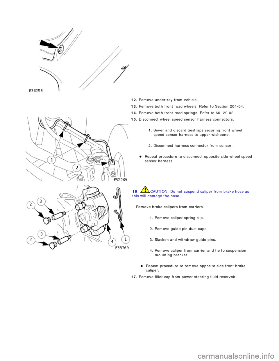
12. Remove undertray from vehicle.
13. Remove both front road wheels. Refer to Section 204-04.
14. Remove both front road springs. Refer to 60. 20.02.
15. Disconnect wheel speed sensor harness connectors.
1. Sever and discard tiestr aps securing front wheel
speed sensor harness to upper wishbone.
2. Disconnect harness connector from sensor.
Repeat procedure to disconnect opposite side wheel speed
sensor harness.
16. CAUTION: Do not suspend caliper from brake hose as
this will damage the hose.
Remove brake calipers from carriers.
1. Remove caliper spring clip.
2. Remove guide pin dust caps.
3. Slacken and withdraw guide pins.
4. Remove caliper from carrier and tie to suspension mounting bracket.
Repeat procedure to remove opposite side front brake
caliper.
17. Remove filler cap from power steering fluid reservoir.
Page 2466 of 2490
Place a piece of wood between jack and crossbeam.
Raise jack to just support crossbeam.
30. From engine compartment, remove crossbeam front RH
securing bolts.
31. Remove power steering fl uid reservoir for access.
Remove reservoir securing nuts and bolts.
Position reservoir for access.
32. From engine compartment, remove crossbeam front LH
securing bolts.
33. Remove crossbeam to engine Hydramount securing bolts.
Remove bolt securing cros smember to Hydramount.
Fully withdraw bolt into crossmember insert.
Repeat procedure to remove and withdraw bolt on
Page 2475 of 2490
22. Install power steering fluid reservoir.
Position reservoir on mounting bracket.
Install reservoir securi ng nuts and bolts.
23. From engine compartment, tighten crossbeam front RH bolts
to 22-28Nm.
24. Install shock absorber on lower wishbone.
Lift lower wishbone to align shock absorber lower
mounting.
Install bolt and nut and ti ghten nut to 43-57Nm.
Repeat procedure to install opposite side shock absorber.
25. Install lower steering column on pinion shaft.
Move column downwards to engage coupling splines on
pinion shaft.
1. Install nut and bolt and tighten to 22-28Nm.


