reservoir JAGUAR X308 1998 2.G Repair Manual
[x] Cancel search | Manufacturer: JAGUAR, Model Year: 1998, Model line: X308, Model: JAGUAR X308 1998 2.GPages: 2490, PDF Size: 69.81 MB
Page 479 of 2490
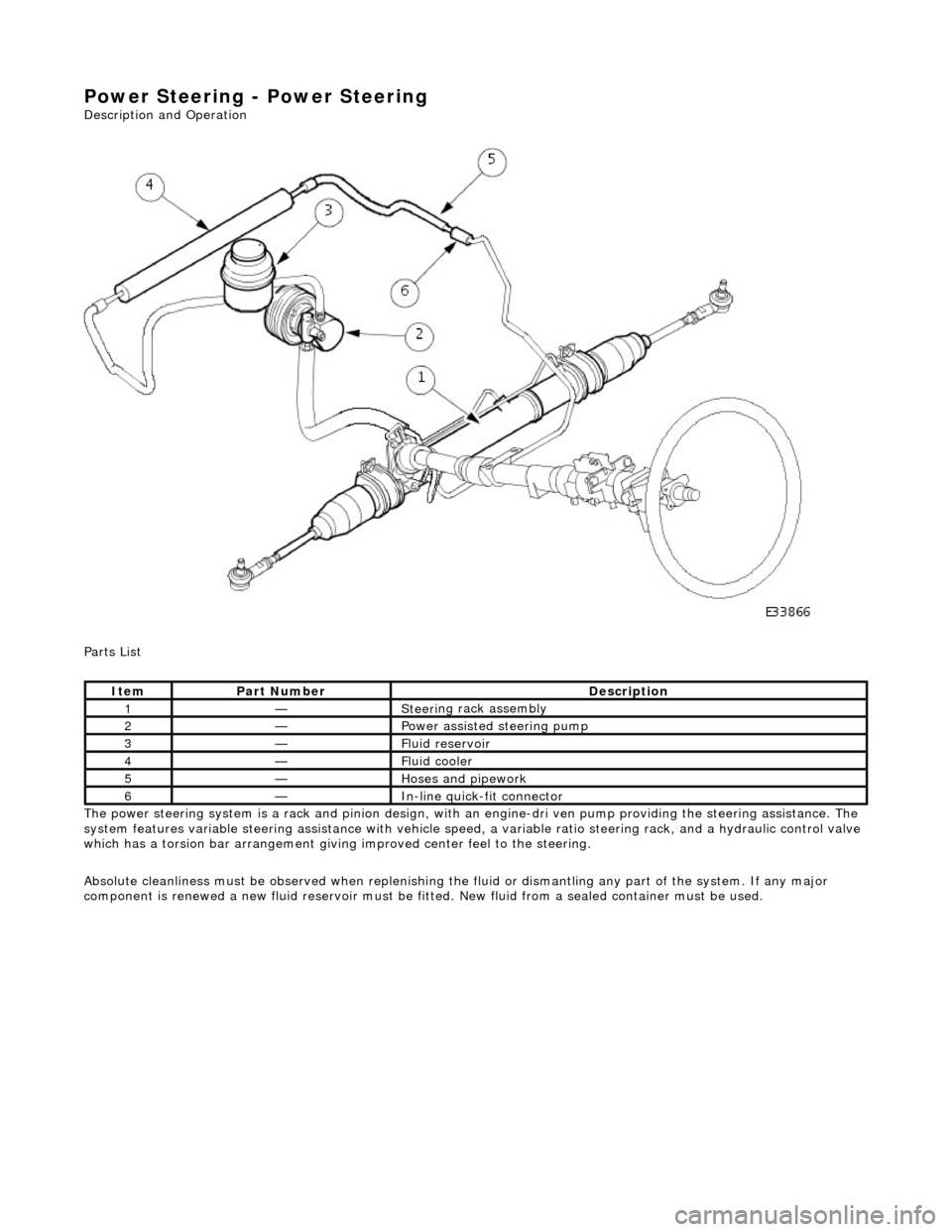
Power Steering - Power Steering
Description an
d Operation
Parts List
The power steering system is a rack and pinion design, with an engine-dri ve n pump providing the steering assistance. The
system features variable steering assistance with vehicle spee d, a variable ratio steering rack, and a hydraulic control valve
which has a torsion bar arrangement giving improved center feel to the steering.
Absolute cleanliness must be observed wh en replenishing the fluid or dismantling any part of the system. If any major
component is renewed a new fluid rese rvoir must be fitted. New fluid from a sealed container must be used.
It
em
Par
t Number
De
scription
1—Steeri
ng rack assembly
2—Power as
sisted steering pump
3—F
luid reservoir
4—F
luid cooler
5—Hoses and pipework
6—In-
line quick-fit connector
Page 484 of 2490
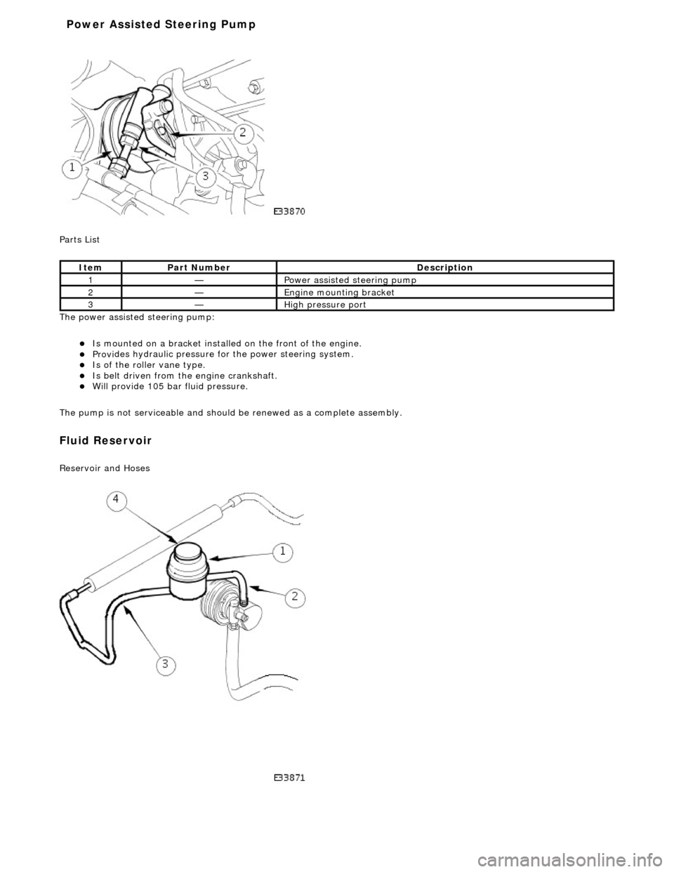
P a
rts List
The power assisted steering pump:
Is mo u
nted on a bracket installe
d on the front of the engine.
Provides hydraul
ic pressure fo
r the power steering system.
Is of the roll
er vane type.
Is belt driven from th
e en
gine crankshaft.
Will provide 1
05 bar f
luid pressure.
The pump is not serviceable and should be renewed as a complete assembly.
Fluid Reservoir
Re
servoir and Hoses
Ite
m
Par
t
Number
De
scr
iption
1—Power as
si
sted steering pump
2—Engine
m
ounting bracket
3—High
pressure port
Power Assisted Steering Pump
Page 485 of 2490
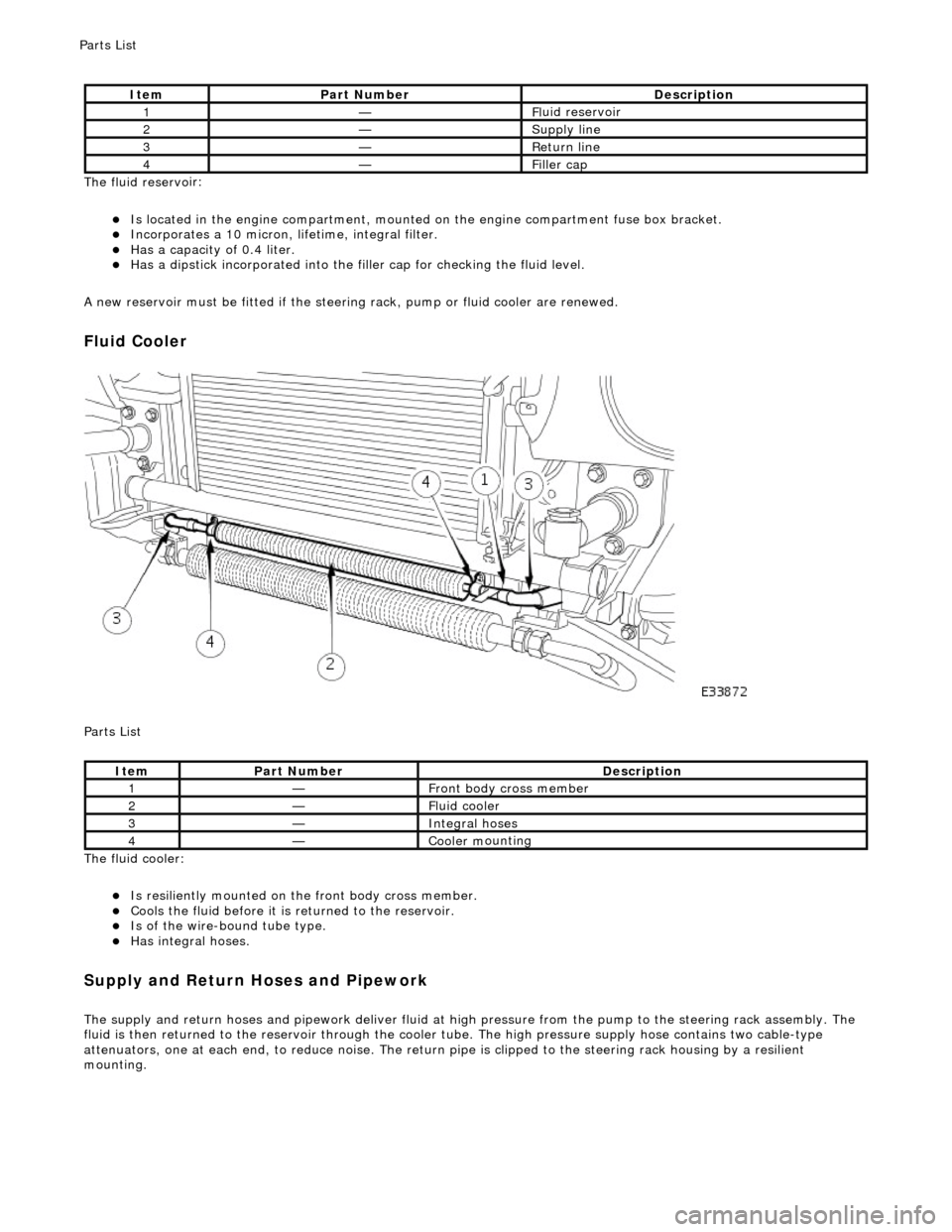
The fluid reservo
ir:
Is lo
cated in the engine compartment, mounted on the engine compartment fuse box bracket.
Incorporates
a 10 micron, li
fetime, integral filter.
Has a cap
acity of 0.4 liter.
Has a dipsti
ck incorporated into the filler cap for checking the fluid level.
A new reservoir must be fitted if the steering rack, pump or fluid cooler are renewed.
Fluid C
ooler
P
arts List
The fluid cooler:
Is
resiliently mounted on th
e front body cross member.
Coo
ls the fluid before it is
returned to the reservoir.
Is
of the wire-bound tube type.
Has i
ntegral hoses.
Supply and Return Hoses a
nd Pipework
The supply and return h
oses and
pipework deliver fluid at high pressure from the pump to th e steering rack assembly. The
fluid is then returned to th e reservoir through the cooler tube. The high pressure supply hose contains two cable-type
attenuators, one at each end, to reduce nois e. The return pipe is clipped to the steering rack housing by a resilient
mounting.
It
em
Par
t Number
De
scription
1—Fl
uid reservoir
2—Supply line
3—R
eturn line
4—Fi
ller cap
It
em
Par
t Number
De
scription
1—Front body cross member
2—F
luid cooler
3—Inte
gral hoses
4—Cooler m
ounting
P
arts List
Page 487 of 2490

m
ember. The quick-fit connector O-rings are not serviceable.
Special tool JD 182 is required to disconnect the quick-fit connector.
Hydraulic System
P
arts List
Hydraulic System
Op
erating Principle
The rot
ary motion of the steering wheel is converted, via the st
eering rack pinion, to the lateral motion of the rack. Steering
assistance is provided by pressurized fluid being directed against a piston operating within the rack cylinder. Rack
movement is achieved by diffe rential pressures being applied on either si de of the rack piston, caused by unequal
restrictions within the hydraulic control valve.
The main components of the hydraulic control valve are the rota ry distributor, control sleeve and hydraulic reaction piston.
It
em
Par
t Number
De
scription
1—F
luid reservoir
2—Pum
p
3—Pressure and fl
ow limiting valve
4—Supply line
5—R
eturn line
6—Steeri
ng rack
7—Pin
ion
8—O
perating cylinder and piston
9—Hydrau
lic control valve
10—Hydraulic reaction
piston
11—Control
sleeve
12—R
otary distributor
13—F
luid cooler
A
quick-fit connector with double O-ring se
als is incorporated in the return line and is clipped to the right-hand chassis side
Page 490 of 2490
Power Steering - Power Steering
Diagn
osis and Testing
Refer to the Description and Operation sub-section for details of the power operated steering system and Servotronic control
system.
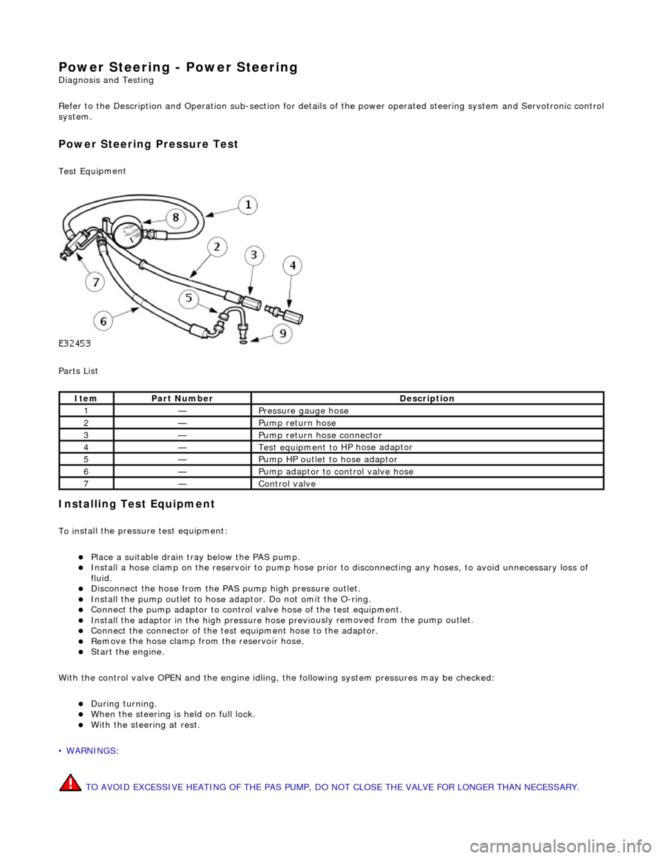
Power Steer ing Pressure Test
Test Equ
i
pment
Parts List
In
stalling Test Equipment
To
in
stall the pressure test equipment:
Pla
c
e a suitable drain tray below the PAS pump.
Install a hose clamp
on
the re
servoir to pump hose prior to disconnecting any hoses, to avoid unnecessary loss of
fluid.
Di sc
onnect the hose from the PAS pump high pres
sure outlet.
Ins
tall the pump outlet to hose ad
aptor. Do not omit the O-ring.
Conn
ect the pump adaptor to control valve hose of the test equipment.
Install th
e adaptor in the high pressure hose previ
ously re
moved from the pump outlet.
Conne
ct the connector of the test equipment hose to the adaptor.
R
e
move the hose clamp fro
m the reservoir hose.
Start th
e engine.
With the control valve OPEN and the engine idling , the following system pressures may be checked:
Du
ring turning.
W
h
en the steering is
held on full lock.
With
the steeri
ng at rest.
• WARNINGS:
TO AVOID EXCESSIVE HEATING OF THE PAS PUMP, DO NOT CLOSE THE VALVE FOR LONGER THAN NECESSARY.
Ite
m
Par
t
Number
De
scr
iption
1—Pressure
gauge hose
2—Pump return hose
3—Pump return hose connector
4—Test equi
pment to
HP hose adaptor
5—Pump HP outlet to hose adaptor
6—Pump adaptor
to control valve hose
7—Control valve
Page 491 of 2490
DO NOT DRIVE THE VEHICLE WITH THE TEST EQUIPMENT INSTALLED.
With the control valve CLOSED the pump maximum output pressure can be checked.
Remov
ing Test Equipment
T
o remove the test equipment:
Install a hose clamp
on the
reservoir to pump hose.
Re
moving the test equipmen
t is a reversal of the installation instructions.
Install a new O-r
ing to the PAS pump high
pressure outlet to hose connection.
Inst
all the original hose to the PAS pump.
R
emove the clamp from the reservoir to pump hose.
Top-up the reservoi
r fluid.
B
leed the PAS system; refe
r to this section.
Refer to PDU
User Guide
T
he PDU will diagnose all electrical components of the system.
Before changing a component, chec k fuse No. 12 (10A) in the left-hand heelboard fu se box. However, if this fuse is faulty a
number of other components wi ll also fail to function.
Page 903 of 2490
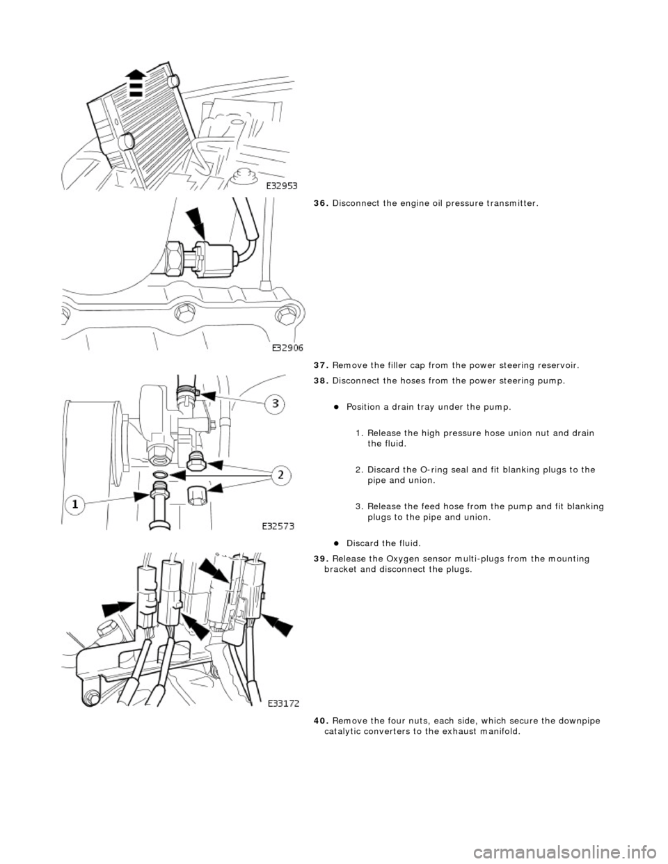
36. Disconnect the engine oi l pressure transmitter.
37. Remove the filler cap from the power steering reservoir.
38. Disconnect the hoses from the power steering pump.
Position a drain tray under the pump.
1. Release the high pressure hose union nut and drain the fluid.
2. Discard the O-ring seal an d fit blanking plugs to the
pipe and union.
3. Release the feed hose from the pump and fit blanking
plugs to the pipe and union.
Discard the fluid.
39. Release the Oxygen sensor multi-plugs from the mounting
bracket and disconnect the plugs.
40. Remove the four nuts, each side, which secure the downpipe
catalytic converters to the exhaust manifold.
Page 928 of 2490
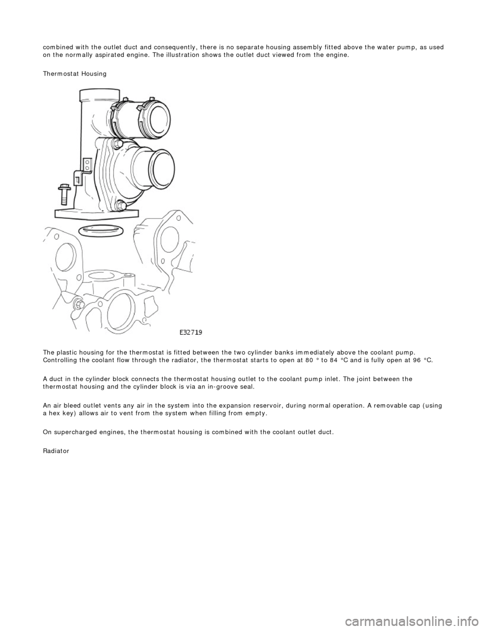
combin
ed with the outlet duct and consequently, there is no separate housin
g assembly fitted above the water pump, as used
on the normally aspirated engine. The illustration shows the outlet duct viewed from the engine.
Thermostat Housing
The plastic housing for the thermostat is fitted between th e two cylinder banks immediately above the coolant pump.
Controlling the coolant flow through the radiator, the thermostat starts to open at 80 ° to 84 °C and is fully open at 96 °C.
A duct in the cylinder block connects the thermostat housing outlet to the coolant pump inlet. The joint between the
thermostat housing and the cylinder block is via an in-groove seal.
An air bleed outlet vents an y air in the system into the expansion reservoir, durin
g normal operation. A removable cap (usin g
a hex key) allows air to vent from the system when filling from empty.
On supercharged engines, the thermostat housin g is combined with the coolant outlet duct.
Radiator
Page 1071 of 2490
I
nstallation
8.
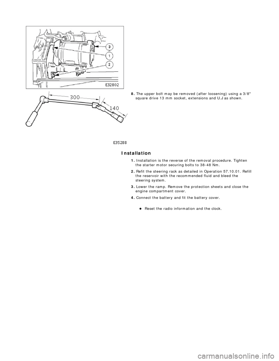
The u
pper bolt may be removed (a
fter loosening) using a 3/8"
square drive 13 mm socket, ex tensions and U.J as shown.
1. Installation is the reverse of the removal procedure. Tighten
the starter motor securing bolts to 38-48 Nm.
2. Refit the steering rack as detail ed in Operation 57.10.01. Refill
the reservoir with the reco mmended fluid and bleed the
steering system.
3. Lower the ramp. Remove the protection sheets and close the
engine compartment cover.
4. Connect the battery and fit the battery cover.
R
eset the radio informat
ion and the clock.
Page 2
of 2
Page 1246 of 2490

El
ectronic Engine Controls - En
gine Coolant Temperature (ECT)
Sensor4.0L NA V8 - AJ 27/3.2L NA V8 - AJ26
Remo
val and Installation
Remova
l
Installation
1. Op
en the engine compartment and fit paintwork protection
sheets.
2. Re
move the engine covers.
3. WA
RNING: ENSURE THAT THE ENGINE IS COLD BEFORE
COMMENCING WORK.
Slacken the coolant reservoir ca p to relieve coolant pressure
and re-tighten.
4. Remove t
he engine coolant temperature sensor.
1. Disconnect the harness plug from the sensor.
2. Remove the sensor and sealing washer.
1. Fitting is the reverse of the removal procedure, noting that a
new sealing washer should be us ed and tighten the sensor as
specified