transmission fluid JAGUAR X308 1998 2.G Service Manual
[x] Cancel search | Manufacturer: JAGUAR, Model Year: 1998, Model line: X308, Model: JAGUAR X308 1998 2.GPages: 2490, PDF Size: 69.81 MB
Page 1360 of 2490

Automatic Transmission/Transaxle - 4.0L NA V8 - AJ27/3.2L NA V8 - AJ26
- Transmission Fluid Pan
In-vehicle Repair
Removal
Installation
1.
Raise the vehicle for access and drain the transmission fluid.
2. Remove the fluid pan.
пЃ¬Remove the twenty-two bolts.
3. Discard the fluid pan gasket and clean the mating faces.
4. Remove the magnets from the fluid pan.
пЃ¬Clean the magnets and refit them to the fluid pan.
1. Installation is th e reverse of the re moval procedure:
2. Tighten the fluid pan bolts to the specified torque figure.
3. Refill the transmission fluid. Refer to Operation 44.24.02.
Page 1361 of 2490

Automatic Transmission/Transaxle - 4.0L NA V8 - AJ27/3.2L NA V8 - AJ26
- Transmission Fluid Pan Gasket
In-vehicle Repair
Removal
Installation
1.
Raise the vehicle for access and drain the transmission fluid.
2. Remove the fluid pan.
пЃ¬Remove the twenty-two bolts.
3. Discard the fluid pan gasket and clean the mating faces.
4. Remove the magnets from the fluid pan.
пЃ¬Clean the magnets and refit them to the fluid pan.
1. Installation is th e reverse of the re moval procedure:
2. Tighten the fluid pan bolts to the specified torque figure.
3. Refill the transmission fluid. Refer to Operation 44.24.02.
Page 1362 of 2490

Automatic Transmission/Transaxle - 4.0L NA V8 - AJ27/3.2L NA V8 - AJ26
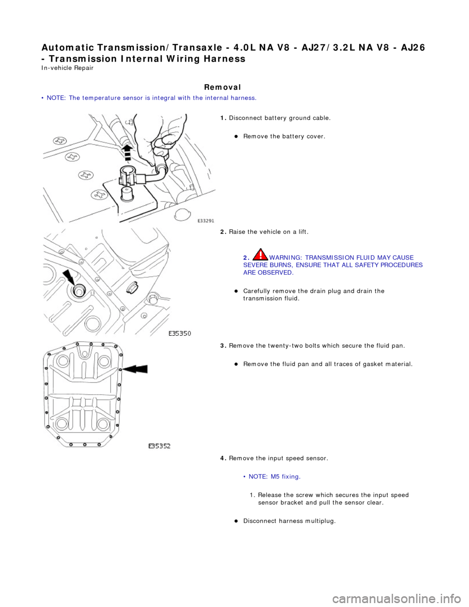
- Transmission Intern al Wiring Harness
In-vehicle Repair
Removal
• NOTE: The temperature sensor is integral with the internal harness.
1. Disconnect battery ground cable.
пЃ¬Remove the battery cover.
2. Raise the vehicle on a lift.
2. WARNING: TRANSMISSION FLUID MAY CAUSE
SEVERE BURNS, ENSURE THAT ALL SAFETY PROCEDURES
ARE OBSERVED.
пЃ¬Carefully remove the drain plug and drain the
transmission fluid.
3. Remove the twenty-two bolts which secure the fluid pan.
пЃ¬Remove the fluid pan and all tr aces of gasket material.
4. Remove the input speed sensor.
• NOTE: M5 fixing. 1. Release the screw which secures the input speed sensor bracket and pull the sensor clear.
пЃ¬Disconnect harness multiplug.
Page 1365 of 2490

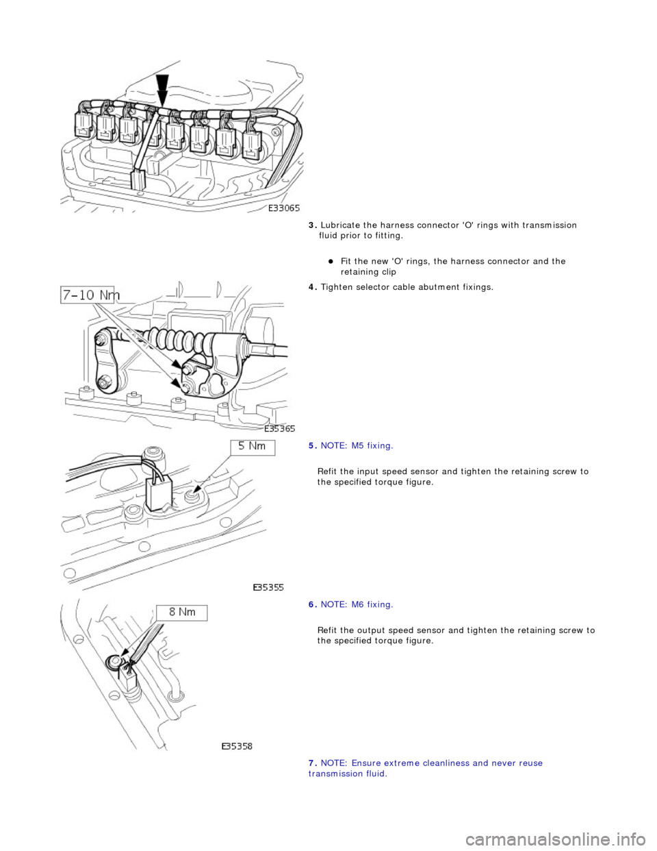
3. Lubricate the harness connector 'O' rings with transmission
fluid prior to fitting.
пЃ¬Fit the new 'O' rings, the harness connector and the
retaining clip
4. Tighten selector cable abutment fixings.
5. NOTE: M5 fixing.
Refit the input speed sensor and tighten the retaining screw to
the specified torque figure.
6. NOTE: M6 fixing.
Refit the output speed sensor and tighten the retaining screw to
the specified torque figure.
7. NOTE: Ensure extreme clea nliness and never reuse
transmission fluid.
Page 1367 of 2490

Automatic Transmission/Transaxle - 4.0L NA V8 - AJ27/3.2L NA V8 - AJ26
- Transmission Internal Wiring Harnes s Electrical Connector O-Ring Seals
In-vehicle Repair
Removal
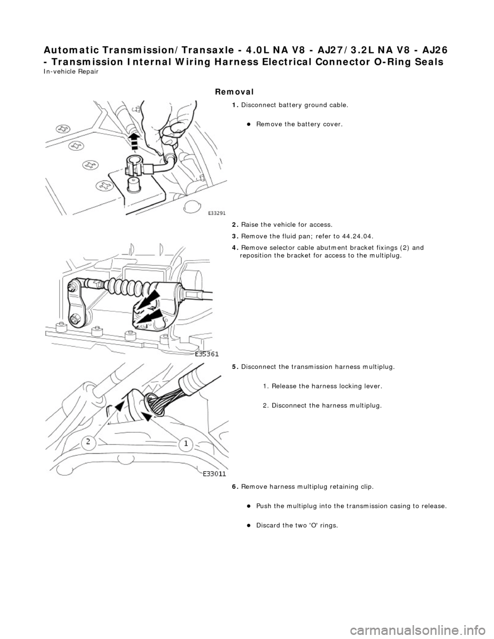
1. Disconnect battery ground cable.
пЃ¬Remove the battery cover.
2. Raise the vehicle for access.
3. Remove the fluid pan; refer to 44.24.04.
4. Remove selector cable abutment bracket fixings (2) and
reposition the bracket for access to the multiplug.
5. Disconnect the transmission harness multiplug.
1. Release the harness locking lever.
2. Disconnect the harness multiplug.
6. Remove harness multiplug retaining clip.
пЃ¬Push the multiplug into the transmission casing to release.
пЃ¬Discard the two 'O' rings.
Page 1368 of 2490

Installation
1. Installation is the reverse of the removal procedure noting
that:
2. Lubricate the new 'O' rings prior to fitting.
3. Tighten the securing bolts, selector cable bracket to
transmission casing, to th e specified torque figure.
4. Connect the battery and fit the battery cover..
пЃ¬Reset the radio and the clock.
5. Refer to (44.24.02) for fluid fill procedure.
Page 1373 of 2490

Automatic Transmission/Transaxle - 4.0L NA V8 - AJ27/3.2L NA V8 - AJ26
- Turbine Shaft Speed (TSS) Sensor
In-vehicle Repair
Removal
1. Disconnect battery ground cable.
пЃ¬Remove the battery cover.
2. Raise the vehicle on a lift.
2. WARNING: TRANSMISSION FLUID MAY CAUSE
SEVERE BURNS, ENSURE THAT ALL SAFETY PROCEDURES
ARE OBSERVED.
пЃ¬Carefully remove the drain plug and drain the
transmission fluid.
3. Remove the twenty-two bolts which secure the fluid pan.
пЃ¬Remove the fluid pan and all tr aces of gasket material.
4. Remove the input speed sensor.
• NOTE: M5 fixing.
1. Release the screw which secures the input speed sensor bracket and pull the sensor clear.
5. Disconnect the multiplug from the speed sensor.
Page 1374 of 2490

Installation
1.
NOTE: M5 fixing.
Connect the multiplug, install the input speed sensor and
securing bracket. Tighten the screw to the specified torque
figure.
2. NOTE: Ensure extreme clea nliness and never reuse
transmission fluid.
Using a new gasket, install the fl uid pan and tighten the twenty-
two fixings to the specified. torque figure.
3. Connect the battery and fit the battery cover..
пЃ¬Reset the radio and the clock.
4. Refer to (44.24.02) for fluid fill procedure.
Page 1376 of 2490

2. Reposition the tank.
8. Install engine lifting bracket 303 - 536 at the rear LH.
9. Support the engine using 303 - 021.
1. Adjust and locate the stan ds in the LH and RH fender
channels and tighten the beam fixings.
2. Engage the support hook s in the lifting brackets.
3. Tighten the support hook adjusters and take the weight of the engine.
10. Raise the vehicle for access.
11. Remove the LH downpipe cata lytic converter (17.50.09).
12. Remove the front muffler (30.10.18).
13. Remove the RH downpipe catalytic converter (17.50.09 and
17.50.10).
14. Drain the transmission fluid, (44.24.02).
15. Locate a transmission jack, Epco V-100 or similar, under the
transmission unit.
пЃ¬Adjust the angle of the jack to suit the transmission.
пЃ¬Secure the side clamps.
пЃ¬Pass the safety chain over the transmission unit and
secure.
Page 1378 of 2490

21. Detach the rotary switch.
1. Remove the switch fixings.
2. Displace the switch harness from the clips.
22. Disconnect the fluid cooler pipes.
пЃ¬Unscrew the cooler pipe tube nu ts, one at each side of the
transmission casing.
пЃ¬Discard the 'O' rings.
пЃ¬Plug the pipes an d transmission.
23. Remove the three bolts which se cure the torque converter to
the drive plate.
1. Remove the access cover.
2. Rotate the crankshaft and hold to prevent movement, and remove the bolts.
24. Remove the LH and RH cataly st mounting brackets from the
transmission case.
пЃ¬Remove the bolts.