transmission fluid JAGUAR X308 1998 2.G User Guide
[x] Cancel search | Manufacturer: JAGUAR, Model Year: 1998, Model line: X308, Model: JAGUAR X308 1998 2.GPages: 2490, PDF Size: 69.81 MB
Page 699 of 2490

пЃ¬STAGE ONE tighten to 14 - 16 Nm.
3. Tighten the securing bolts in two stages and in the order
shown.
пЃ¬STAGE TWO tighten to 95 - 125 Nm.
4. Refit the Transmission, Catalytic Converters and the Front
Muffler, Air Intake Tube an d Engine Covers. Refill the
transmission with new fluid.
пЃ¬Refer to Operation 44.20. 01 Transmission Install, in
Section 307-01B, which includes each of the above
operations.
5. Remove the paint protection sheets and close the engine
compartment cover.
6. Connect the battery and fit the battery cover.
пЃ¬Refer to the Battery Reconnection Procedure 86.15.15.
Page 901 of 2490
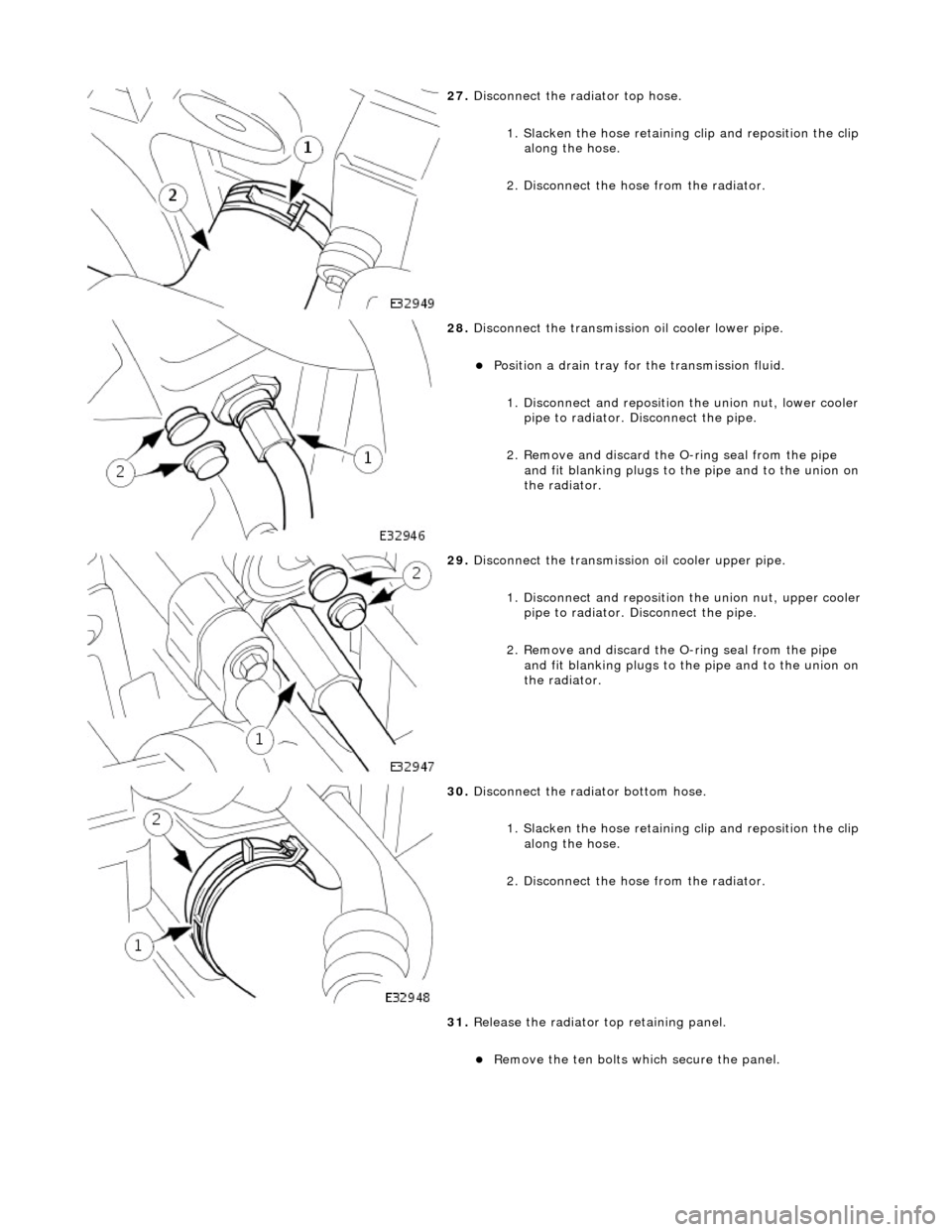
27. Disconnect the radiator top hose.
1. Slacken the hose retaining clip and reposition the clip
along the hose.
2. Disconnect the hose from the radiator.
28. Disconnect the transmission oil cooler lower pipe.
пЃ¬Position a drain tray for the transmission fluid.
1. Disconnect and reposition the union nut, lower cooler pipe to radiator. Di sconnect the pipe.
2. Remove and discard the O- ring seal from the pipe
and fit blanking plugs to the pipe and to the union on
the radiator.
29. Disconnect the transmission oil cooler upper pipe.
1. Disconnect and reposition the union nut, upper cooler pipe to radiator. Di sconnect the pipe.
2. Remove and discard the O- ring seal from the pipe
and fit blanking plugs to the pipe and to the union on
the radiator.
30. Disconnect the radiator bottom hose.
1. Slacken the hose retaining clip and reposition the clip
along the hose.
2. Disconnect the hose from the radiator.
31. Release the radiator top retaining panel.
пЃ¬Remove the ten bolts which secure the panel.
Page 977 of 2490
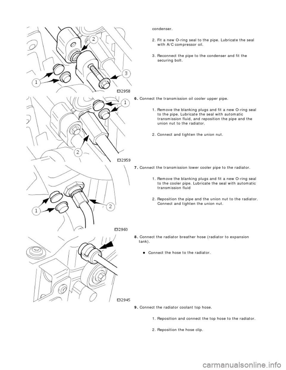
conde
nser.
2. Fit a new O-ring seal to the pipe. Lubricate the seal with A/C compressor oil.
3. Reconnect the pipe to the condenser and fit the securing bolt.
6. Conne
ct the transmission
oil cooler upper pipe.
1. Remove the blanking plugs and fit a new O-ring seal to the pipe. Lubricate the seal with automatic
transmission fluid, and re position the pipe and the
union nut to the radiator.
2. Connect and tighten the union nut.
7. Conne
ct the transmission lower cooler pipe to the radiator.
1. Remove the blanking plugs and fit a new O-ring seal to the cooler pipe. Lubricate the seal with automatic
transmission fluid
2. Reposition the pipe and th e union nut to the radiator.
Connect and tighten the union nut.
8. Connect
the radiator breather
hose (radiator to expansion
tank).
пЃ¬Conne
ct the hose to the radiator.
9. Connect the radiator coolant top hose.
1. Reposition and connect the top hose to the radiator.
2. Reposition the hose clip.
Page 978 of 2490
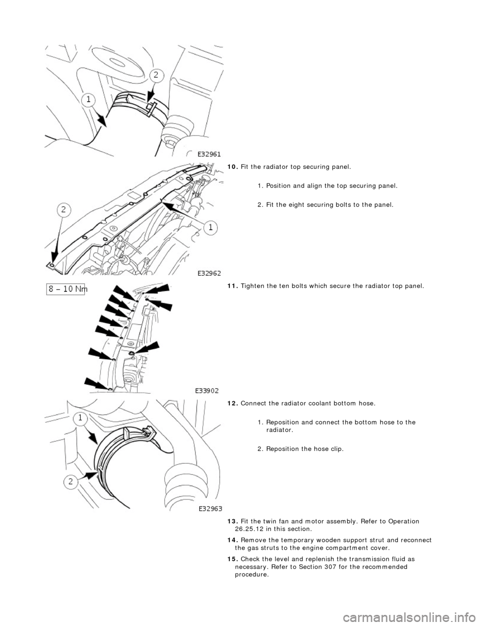
10. F
it the radiator top securing panel.
1. Position and align th e top securing panel.
2. Fit the eight securing bolts to the panel.
11. Tigh
ten the ten bolts which secu
re the radiator top panel.
12. Connect
the radiator coolant bottom hose.
1. Reposition and connect the bottom hose to the radiator.
2. Reposition the hose clip.
13. Fit the twin fan and motor assembly. Refer to Operation
26.25.12 in this section.
14. Remove the temporary wooden support strut and reconnect
the gas struts to the engine compartment cover.
15. Check the level and replenish the transmission fluid as
necessary. Refer to Section 307 for the recommended
procedure.
Page 984 of 2490

conden
ser.
2. Fit a new O-ring seal to the pipe. Lubricate the seal with A/C compressor oil.
3. Reconnect the pipe to the condenser and fit the securing bolt.
6. Conne ct
the transmission
oil cooler upper pipe.
1. Remove the blanking plugs and fit a new O-ring seal to the pipe. Lubricate the seal with automatic
transmission fluid, and re position the pipe and the
union nut to the radiator.
2. Connect and tighten the union nut.
7. Conne ct
the transmission lower cooler pipe to the radiator.
1. Remove the blanking plugs and fit a new O-ring seal to the cooler pipe. Lubricate the seal with automatic
transmission fluid
2. Reposition the pipe and th e union nut to the radiator.
Connect and tighten the union nut.
8. Connect the radiator br
eather
hose (radiator to expansion
tank).
пЃ¬Conne ct
the hose to the radiator.
9. Connect the radiator coolant top hose.
1. Reposition and connect the top hose to the radiator.
2. Reposition the hose clip.
Page 985 of 2490
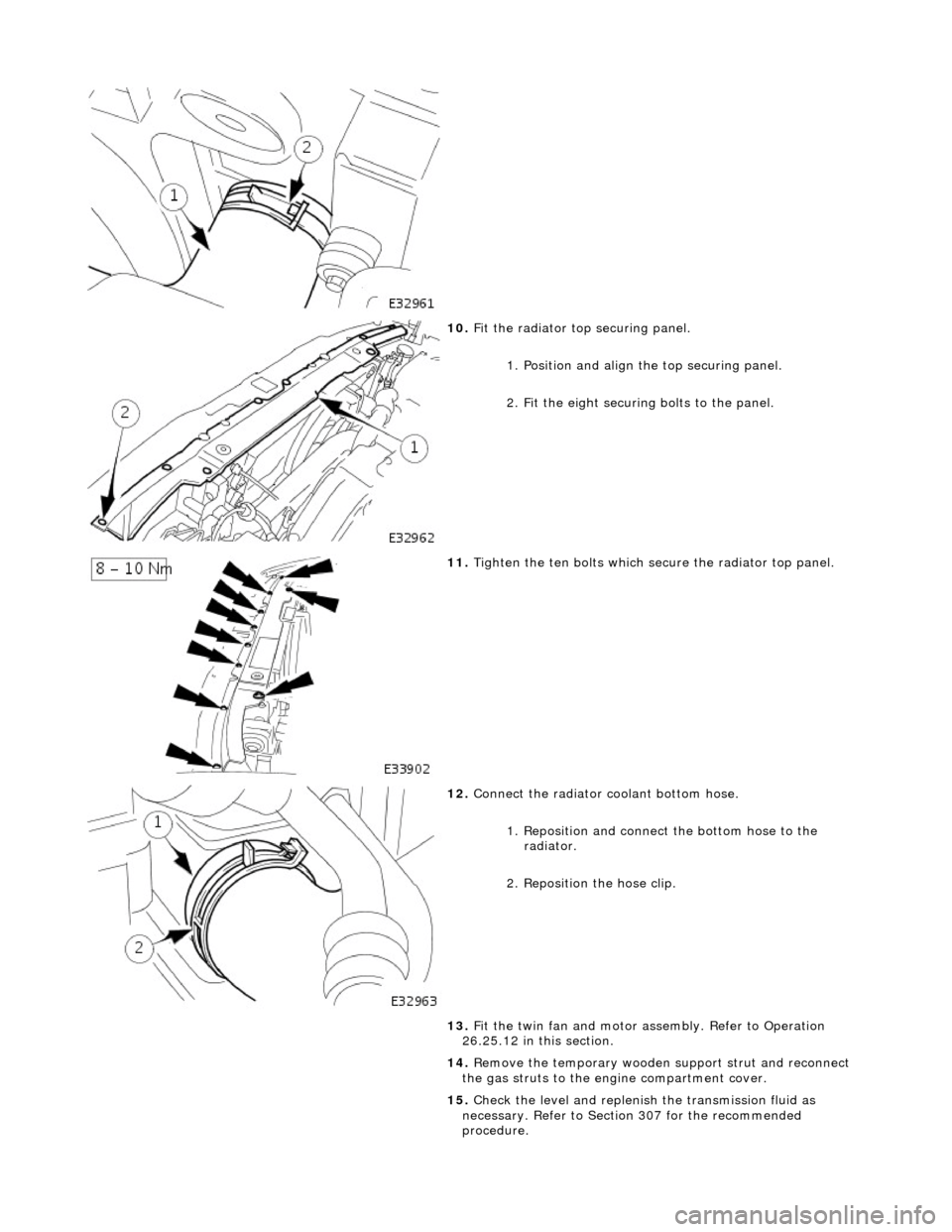
10
.
Fit the radiator top securing panel.
1. Position and align th e top securing panel.
2. Fit the eight securing bolts to the panel.
11
.
Tighten the ten bolts which secu re the radiator top panel.
12
.
Connect the radiator coolant bottom hose.
1. Reposition and connect the bottom hose to the radiator.
2. Reposition the hose clip.
13. Fit the twin fan and motor assembly. Refer to Operation
26.25.12 in this section.
14. Remove the temporary wooden support strut and reconnect
the gas struts to the engine compartment cover.
15. Check the level and replenish the transmission fluid as
necessary. Refer to Section 307 for the recommended
procedure.
Page 1260 of 2490
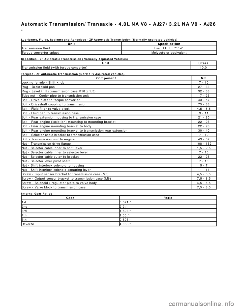
Automatic Transmission/Transaxle - 4.0L NA V8 - AJ27/3.2L NA V8 - AJ26
-
Lubri c
ants, Fluids, Sealants and Adhesives - ZF Au
tomatic Transmission (Normally Aspirated Vehicles)
Capacities - ZF Automatic Transmission (Normally Aspirated Vehicles)
Torques - ZF Automatic Transmission (Normally Aspirated Vehicles)
Internal Gear Ratios
UnitS p
ecification
Transmissi
on fluidEsso
ATF LT 71141
Torque converter spigotMolyc
o
te or equivalent
UnitLi
t
ers
Transmissi
on fluid (with
torque converter)
10
,0
Com p
onent
Nm
Locki
n
g ferrule - Shift knob
7 -
10
P
l
ug - Drain fluid pan
27
-
33
P
l
ug - Level / fill (transmission case M18 x 1.5)
32
-
38
Tu
be
nut - Cooler pipe to transmission unit
17
-
23
B
o
lt - Drive plate to torque converter
43
-
57
B
o
lt - Driveshaft coupling to transmission
75
-
88
Bo
lt
- Fluid filter to valve block
4,
5 -
5,5
Bolt
-
Fluid pan to transmission case
9 -
11
B
o
lt - Rear extension housing to transmission case
21
-
25
Bolt
-
Rear engine (isolation) mounting to mounting bracket
22
-
28
Bolt -
Rear engine moun
ting bracket to body
22
-
28
Bolt
-
Rear engine mounting bracke
t to transmission rear extension
30 -
40
B
o
lt - Selector cable bracket to transmission case
7 -
10
Bolt
-
Transmission unit to engine
43
-
57
Nu
t -
Transmission drive flange
1
08 -
132
Nu
t -
Selector cable inner to shift lever
1,
5 -
2,5
Nu
t -
Selector cable inner to selector lever
7 -
10
Nu
t -
Selector cable outer to bracket
22
-
28
Nu
t
- Selector lever pivot shaft
7 -
10
Nu
t -
Shift interlock solenoid to housing
5 -
7
Nut -
Shift interlock solenoid actuating lever
11
-
13
Sc
re
w - Input sensor bracket to transmission case (M5)
4,
5 -
5,5
Screw
-
Output sensor bracket to transmission case (M6)
7,
5 -
8,5
Screw
-
Solenoid / regulator plate to valve body
4,
5 -
5,5
Sc
re
w - Valve block to transmission case
7,
5 -
8,5
GearRatio
1s
t3,57
1:1
2n
d2,2:
1
3r
d1,50
8:1
4t
h1,00
:1
5t
h0,80
3:1
Re
ve
rse
4,
06
3:1
Page 1261 of 2490
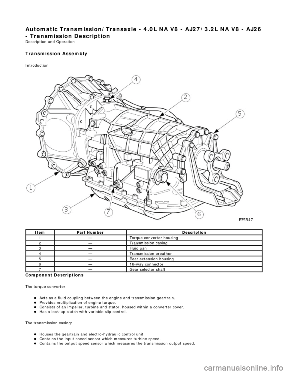
Automatic Transmission/Transaxle - 4.0L NA V8 - AJ27/3.2L NA V8 - AJ26
- Transmission Descriptio
n
Description an
d Operation
Transmission As
sembly
Int
roduction
Compon
ent Descriptions
The t
orque converter:
пЃ¬Acts as a fluid
coupling between the
engine and transmission geartrain.
пЃ¬P
rovides multiplication of engine torque.
пЃ¬Cons
ists of an impeller, turbine and stat
or, housed within a converter cover.
пЃ¬Has a l
ock-up clutch with variable slip control.
The transmission casing:
пЃ¬Houses the geartrain and elec t
ro-hydraulic control unit.
пЃ¬Contains
the input speed sensor which measures turbine speed.
пЃ¬Contai
ns the output speed sensor which measures the transmission output speed.
It
em
Par
t Number
De
scription
1—Torque c
onverter housing
2—Tran
smission casing
3—Fluid pan
4—Transmission bre
ather
5—Re
ar extension housing
6—16
-way connector
7—Gear s
elector shaft
Page 1262 of 2490
пЃ¬Contains th
e hydraulic system pump.
пЃ¬Contains
th
e fluid temperature sensor.
The epicyclic geartrain:
пЃ¬Provi des fi
ve forward gears and Reverse.
пЃ¬Has
h
ydraulically actuated, multi-disk clutches, to select the required gear ratios.
пЃ¬Feature
s clutch-to-clutch operation to permit
gear shifts for uninterrupted power flow.
The electro-hydraulic control unit:
пЃ¬Is lo c
ated in the lower part of
the unit, within the fluid pan.
пЃ¬Is controlled
by the TCM (transmissio
n control module), and the manual selector valve which is cable operated.
пЃ¬Re
gulates the flow of fluid to the ge
artrain clutches via three solenoid-operated valv es and the manual selector
valve.
пЃ¬Has fi ve pressure
regulators for controll
ing fluid pressures within the system.
пЃ¬Is con
nected to the TCM via a 16-way connector mounted on
the left-hand side of the transmission casing. Refer to
Connector Pins Identification, Section 307-01A.
The hydraulic system pump:
пЃ¬Is l o
cated at the front of the transmission casing.
пЃ¬Is dri
v
en from the impeller hub,
pressurising the fluid whenever the engine is running.
пЃ¬Supplie
s fluid under pressure to the torq
ue converter, geartrain, electro-hydr aulic control unit and the lubrication
circuit.
пЃ¬D r
aws fluid from the fluid pa
n below the transmission casing, through a filter.
The rear extension housing:
пЃ¬Is bolt
ed to the rear of the transmission casing.
пЃ¬Provides the rear engine / transmi
ssion mo
unting point; refer to section 303-01.
пЃ¬Carrie
s the transmission output shaft oil seal.
Filled-for-l
i
fe Fluid System
The
transm
ission is 'filled for life' and
does not require fluid changes, except where extreme driving conditions prevail.
Routine level checking is not required and a dipstick is not pr ovided. A level / filler plug is fitted for level checking and
replenishment, following service actions; see 303-01 General Procedures.
Transmission Torque Converter
Page 1265 of 2490
Voltage is monitored at the regulators and solenoids for continuity and shorts. For example, when a solenoid is ON the
voltage on the TCM side should be ground , when OFF the voltage should be +12.
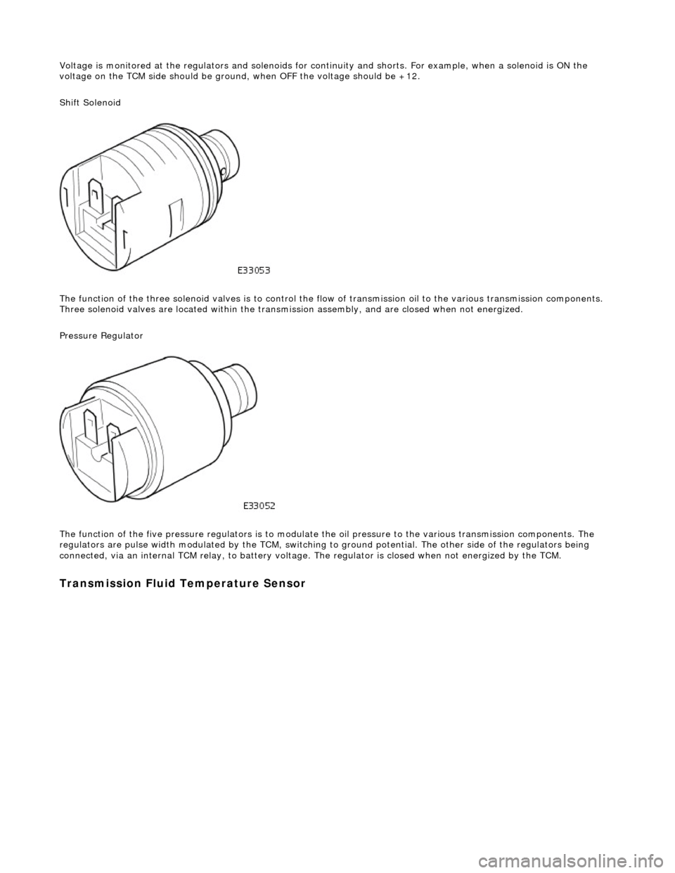
Shift Solenoid
The function of the three soleno id valves is to control the flow of transmissi on oil to the various transmission components.
Three solenoid valves are located wi thin the transmission assembly, and are closed when not energized.
Pressure Regulator
The function of the five pressu re regulators is to modulate the oil pressure to the various transmission components. The
regulators are pulse width modulated by the TCM, switching to ground potential. The other side of the regulators being
connected, via an internal TCM relay, to battery voltage. The regulator is closed when not energized by the TCM.
Transmission Fluid Temperature Sensor