transmission fluid JAGUAR X308 1998 2.G Repair Manual
[x] Cancel search | Manufacturer: JAGUAR, Model Year: 1998, Model line: X308, Model: JAGUAR X308 1998 2.GPages: 2490, PDF Size: 69.81 MB
Page 1386 of 2490
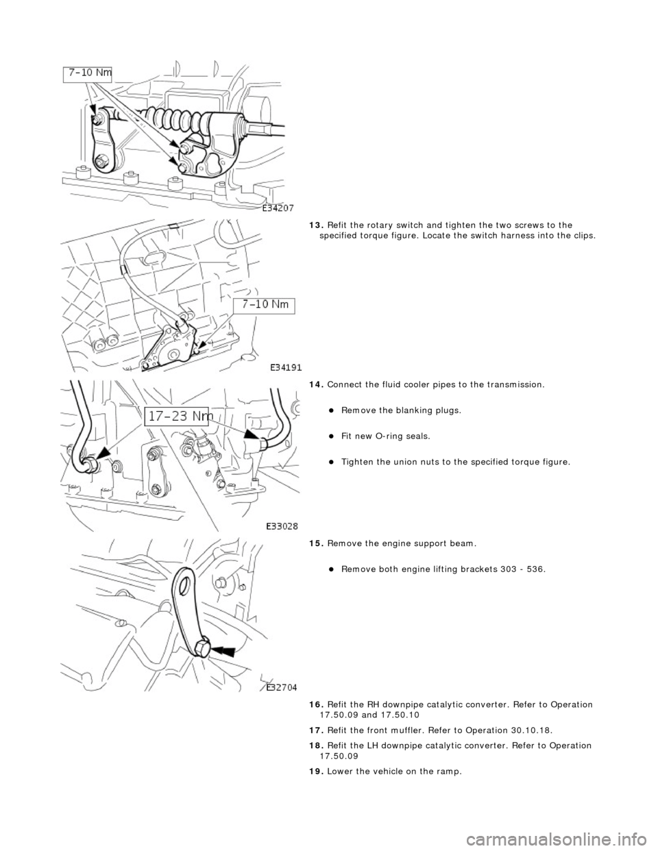
13. Refit the rotary switch and tighten the two screws to the
specified torque figure. Locate the switch harness into the clips.
14. Connect the fluid cooler pipes to the transmission.
пЃ¬Remove the blanking plugs.
пЃ¬Fit new O-ring seals.
пЃ¬Tighten the union nuts to the specified torque figure.
15. Remove the engine support beam.
пЃ¬Remove both engine lifting brackets 303 - 536.
16. Refit the RH downpipe catalytic converter. Refer to Operation
17.50.09 and 17.50.10
17. Refit the front muffler. Refer to Operation 30.10.18.
18. Refit the LH downpipe catalytic converter. Refer to Operation
17.50.09
19. Lower the vehicle on the ramp.
Page 1387 of 2490
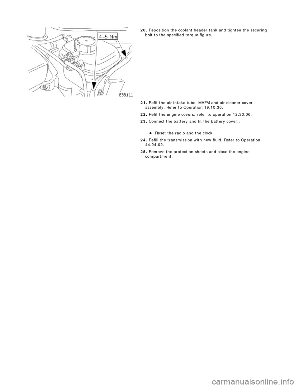
20. Reposition the coolant header tank and tighten the securing
bolt to the specified torque figure.
21. Refit the air intake tube, MAFM and air cleaner cover
assembly. Refer to Operation 19.10.30.
22. Refit the engine covers. re fer to operation 12.30.06.
23. Connect the battery and fit the battery cover..
пЃ¬Reset the radio and the clock.
24. Refill the transmission with new fluid. Refer to Operation
44.24.02.
25. Remove the protection sheets and close the engine
compartment.
Page 1388 of 2490
Automatic Transmission/Transaxle - 4.0L SC V8 - AJ26 -
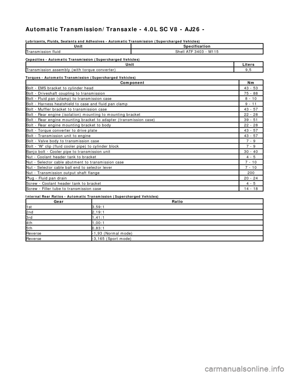
Lubricants, Fluids, Sealants and Adhesives - Automatic Transmission (Supercharged Vehicles)
Capacities - Automatic Transmission (Supercharged Vehicles)
Torques - Automatic Transmission (Supercharged Vehicles)
Internal Rear Ratios - Automatic Transmission (Supercharged Vehicles)
UnitSpecification
Transmission fluidShell ATF 3403 - M115
UnitLiters
Transmission assembly (with torque converter)9,5
ComponentNm
Bolt - EMS bracket to cylinder head43 - 53
Bolt - Driveshaft coupling to transmission75 - 88
Bolt - Fluid pan (clamp) to transmission case8 - 10
Bolt - Harness heatshield to case and fluid pan clamp9 - 11
Bolt - Muffler bracket to transmission case43 - 57
Bolt - Rear engine (isolation) mounting to mounting bracket22 - 28
Bolt - Rear engine mounting brac ket to adapter (transmission case)39 - 51
Bolt - Rear engine mounting bracket to body22 - 28
Bolt - Torque converter to drive plate43 - 57
Bolt - Transmission unit to engine43 - 57
Bolt - Valve body to transmission case7 - 9
Bolt - 'W' clip (fluid cooler pipe) to cylinder block7 - 9
Banjo bolt - Cooler pipe to transmission unit30 - 40
Nut - Coolant header tank to bracket4 - 5
Nut - Selector cable abutment to transmission case7 - 10
Nut - Selector cable ball end to selector lever7 - 10
Nut - Transmission output shaft flange200
Plug - Fluid pan drain20 - 24
Screw - Coolant header tank to bracket4 - 5
Screw - Filler tube to transmission case14 - 18
GearRatio
1st3,59:1
2nd2,19:1
3rd1,41:1
4th1,00:1
5th0,83:1
Reverse-1,93 (Normal mode)
Reverse-3,165 (Sport mode)
Page 1389 of 2490
Automatic Transmission/Transaxle - 4.0L SC V8 - AJ26 - Transmission
Description
Description and Operation
Transmission Assembly
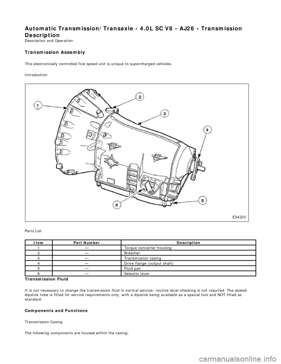
This electronically controlled five speed unit is unique to supercharged vehicles.
Introduction
Parts List
Transmission Fluid
It is not necessary to change the transmis sion fluid in normal service; routine level checking is not required. The sealed
dipstick tube is fitted for service requir ements only, with a dipstick being availa ble as a special tool and NOT fitted as
standard.
Components and Functions
Transmission Casing
The following components are housed within the casing;
ItemPart NumberDescription
1—Torque converter housing
2—Breather
3—Transmission casing
4—Drive flange (output shaft)
5—Fluid pan
6—Selector lever
Page 1390 of 2490
пЃ¬Stator, intermediate and output shafts. пЃ¬Three epicyclic geartrains. пЃ¬Six multi-disc clutch/brake packs. пЃ¬Two freewheels (One-way clutches). пЃ¬Hydraulic pump. пЃ¬Parking lock assembly. пЃ¬Electro-hydraulic control unit. пЃ¬Internal harness and 13 pin connector with bayonet lock.
Hydraulic pump
пЃ¬This engine driven pump is located at the front of the transmission casing and provides pressure for the hydraulic
functions.
пЃ¬Supplies fluid under pressure to the torq ue converter, geartrain, electro-hydraulic control unit and the lubrication
circuit.
пЃ¬Draws fluid from the fluid pa n below the transmission casing, through a filter.
Parking lock
This component prevents movement of th e vehicle by engaging a fixed pawl with the parking lock gear located on the
output shaft. The pawl is engaged by movi ng the gear selector lever to the park (P) position.
Electro-hydraulic control unit
This unit, mounted in the transmission lower case, converts signals, mechanical from the J-gate and electrical from the
TCM, into hydraulic functions.
The following components ar e assembled to the unit:
пЃ¬Selector valve. пЃ¬Shift plate. пЃ¬Control valve - modulating pressure. пЃ¬Control valve - shift pressure. пЃ¬Solenoid valve 1 <-> 2 and 4 <-> 5 shift. пЃ¬Solenoid valve 3 <-> 4 shift. пЃ¬Solenoid valve 2 <-> 3 shift. пЃ¬Solenoid valve - converter lock-up. пЃ¬Speed sensors (2). пЃ¬Temperature sensor.
Speed sensors
There are two speed sensors within the transmission assembly which provide input to the TCM. These inputs, when used in
conjunction with CAN data relative to engine speed (from ECM) and road speed (from ABS), are used to electronically
control the transmission.
Temperature sensor
The output from this sensor allows the TCM to compensate for the affect of fluid temperature on shift time and quality
Control Systems
Hydraulic Control
The selector valve is operated directly by the J-gate and directs fluid flow for P R N D.
Of the four solenoid valves, 3 control shifts and 1 controls converter lock-up. One control valve controls modulating pressure
and the other shift pressure.
Regulating valves are used to maintain/control pressure for lu brication, normal operating functions, and the supply to the
control valves and shift valves.
Page 1394 of 2490
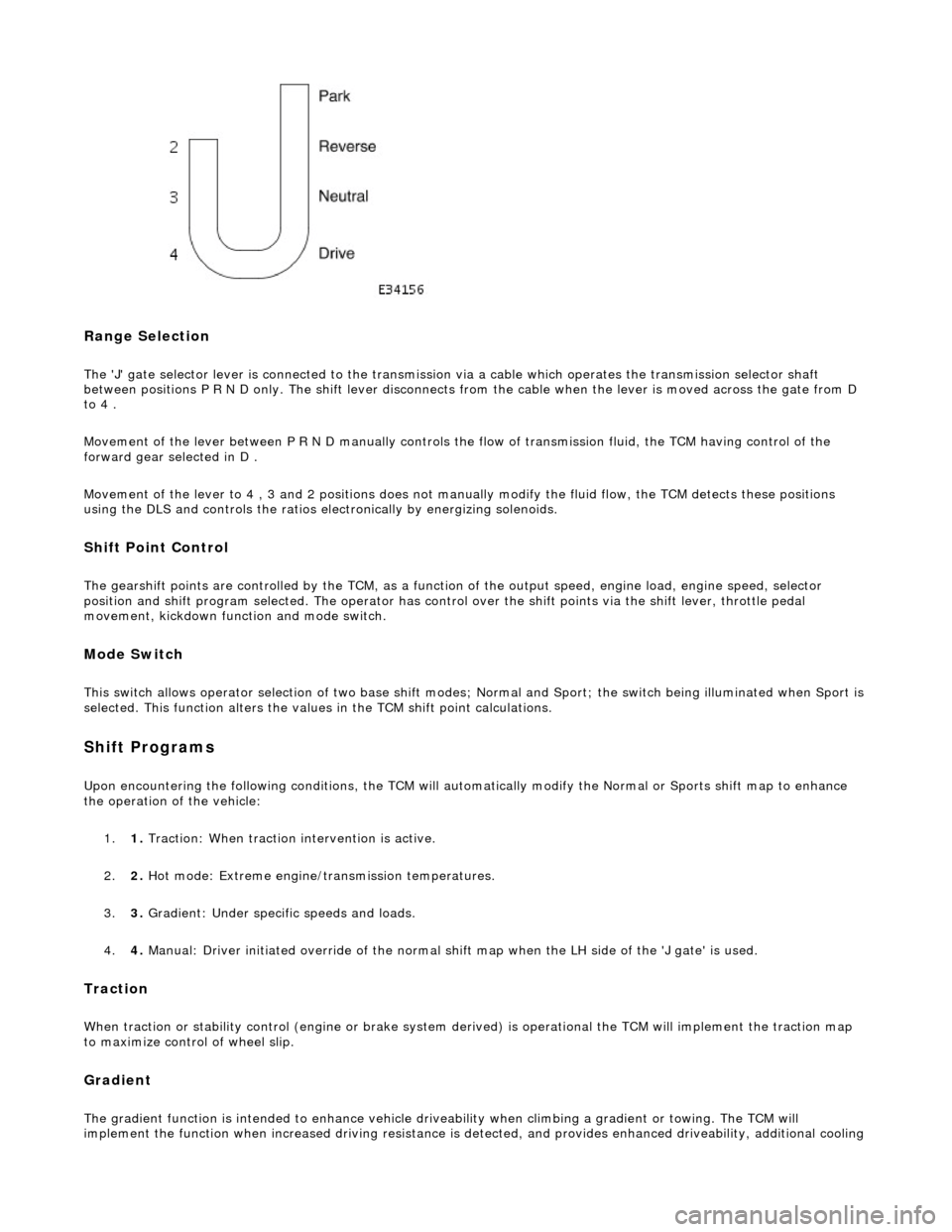
Range Selection
The 'J' gate selector lever is connected to the transmission via a cable which operates the transmission selector shaft
between positions P R N D only. The shift lever disconnects from the cable when the lever is moved across the gate from D
to 4 .
Movement of the lever between P R N D manu ally controls the flow of transmission fluid, the TCM having control of the
forward gear selected in D .
Movement of the lever to 4 , 3 and 2 positions does not manu ally modify the fluid flow, the TCM detects these positions
using the DLS and controls the ratios electronically by energizing solenoids.
Shift Point Control
The gearshift points are controlled by the TCM, as a function of the output speed, engine load, engine speed, selector
position and shift program selected. The operator has control over the shift points via the shift lever, throttle pedal
movement, kickdown function and mode switch.
Mode Switch
This switch allows operator selection of two base shift modes; Normal and Sport; th e switch being illuminated when Sport is
selected. This function alters the values in the TCM shift point calculations.
Shift Programs
Upon encountering the following conditions, the TCM will auto matically modify the Normal or Sports shift map to enhance
the operation of the vehicle:
1. 1. Traction: When traction intervention is active.
2. 2. Hot mode: Extreme engine/transmission temperatures.
3. 3. Gradient: Under specific speeds and loads.
4. 4. Manual: Driver initiated override of the normal shif t map when the LH side of the 'J gate' is used.
Traction
When traction or stability control (engine or brake system de rived) is operational the TCM will implement the traction map
to maximize control of wheel slip.
Gradient
The gradient function is intended to enhance vehicle drivea bility when climbing a gradient or towing. The TCM will
implement the function when increased driving resistance is de tected, and provides enhanced driveability, additional cooling
Page 1429 of 2490
Automatic Transmission/Transaxle - 4.0L SC V8 - AJ26 - Transmission
Fluid Drain and Refill
General Procedures
Special Tool(s)
Dipstick
307-379
1. Disconnect the battery ground lead.
2. Raise the vehicle for access.
3. NOTE: This procedure will not re move residual fluid from the
torque converter.
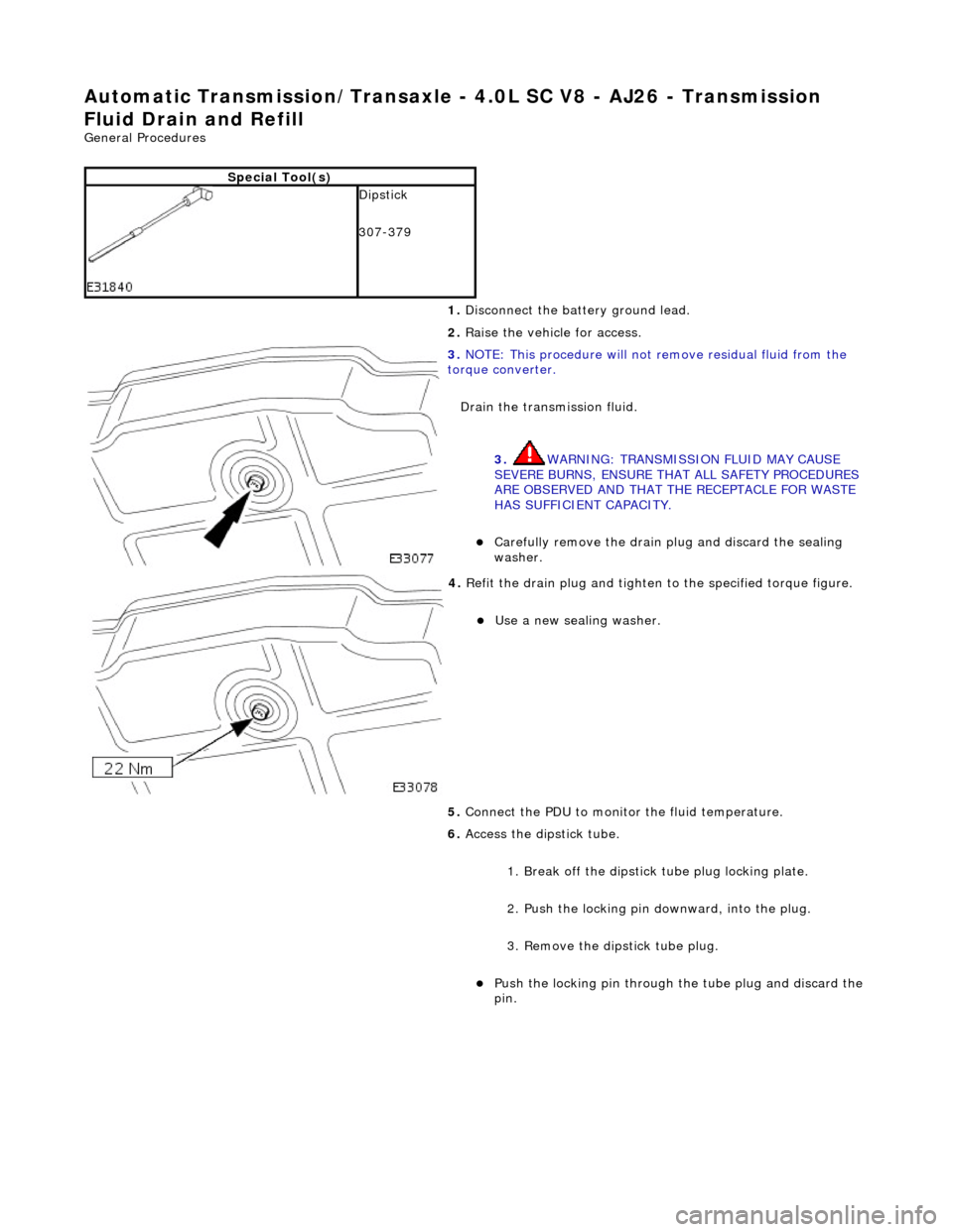
Drain the transmission fluid.
3. WARNING: TRANSMISSION FLUID MAY CAUSE
SEVERE BURNS, ENSURE THAT ALL SAFETY PROCEDURES
ARE OBSERVED AND THAT THE RECEPTACLE FOR WASTE
HAS SUFFICIENT CAPACITY.
пЃ¬Carefully remove the drain pl ug and discard the sealing
washer.
4. Refit the drain plug and tighten to the specified torque figure.
пЃ¬Use a new sealing washer.
5. Connect the PDU to monitor the fluid temperature.
6. Access the dipstick tube.
1. Break off the dipstick tube plug locking plate.
2. Push the locking pin downward, into the plug.
3. Remove the dipstick tube plug.
пЃ¬Push the locking pin through the tube plug and discard the
pin.
Page 1430 of 2490
7. CAUTION: It is essential that only the specified fluid is
used.
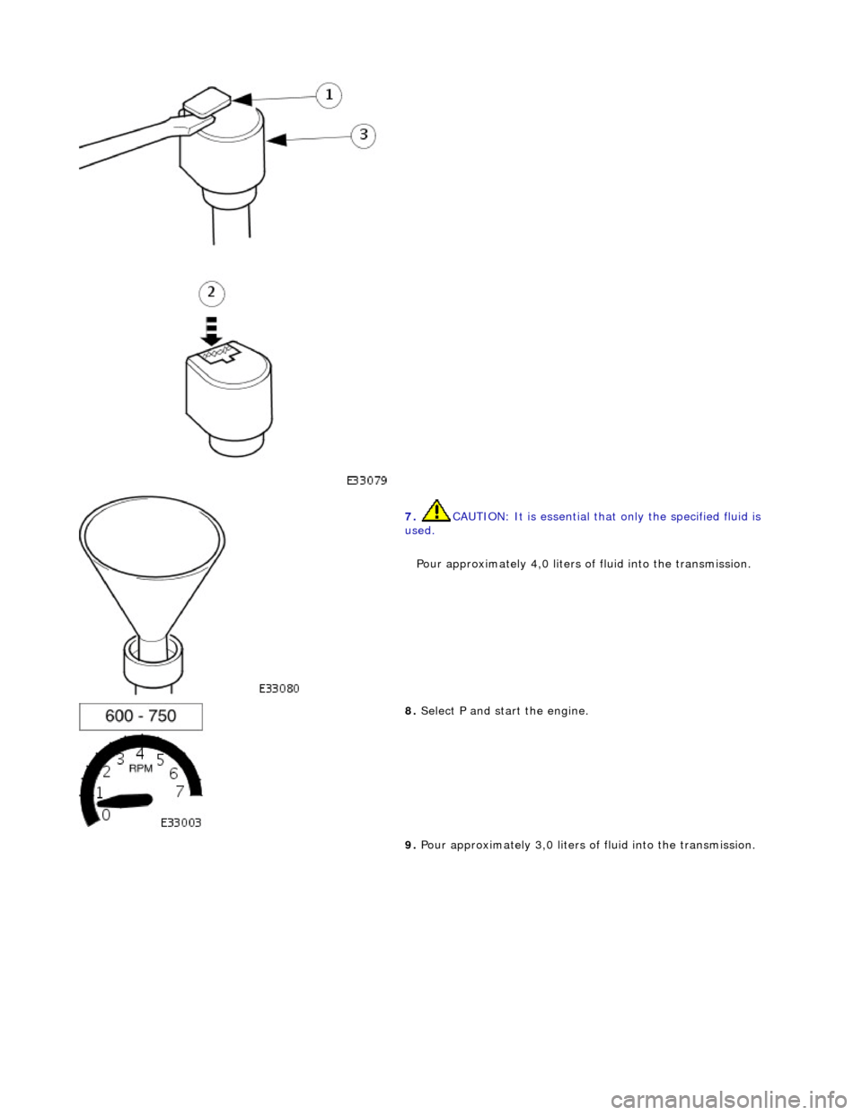
Pour approximately 4,0 liters of fluid into the transmission.
8. Select P and start the engine.
9. Pour approximately 3,0 liters of fluid into the transmission.
Page 1431 of 2490
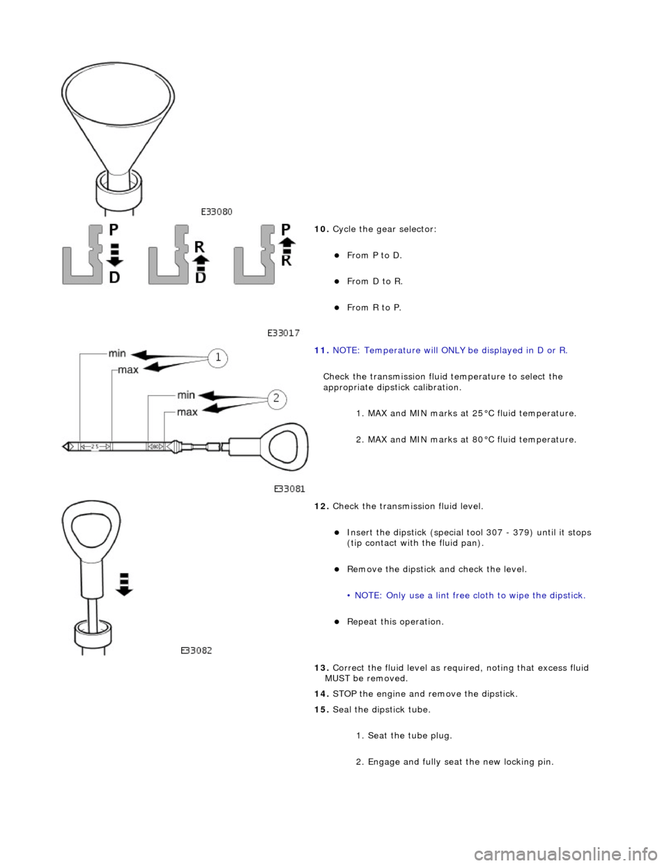
10. Cycle the gear selector:
пЃ¬From P to D.
пЃ¬From D to R.
пЃ¬From R to P.
11. NOTE: Temperature will ONLY be displayed in D or R.
Check the transmission fluid temperature to select the
appropriate dipstick calibration. 1. MAX and MIN marks at 25В°C fluid temperature.
2. MAX and MIN marks at 80В°C fluid temperature.
12. Check the transmission fluid level.
пЃ¬Insert the dipstick (special tool 307 - 379) until it stops
(tip contact with the fluid pan).
пЃ¬Remove the dipstick an d check the level.
• NOTE: Only use a lint free cloth to wipe the dipstick.
пЃ¬Repeat this operation.
13. Correct the fluid leve l as required, noting that excess fluid
MUST be removed.
14. STOP the engine and remove the dipstick.
15. Seal the dipstick tube.
1. Seat the tube plug.
2. Engage and fully seat the new locking pin.
Page 1436 of 2490

Automatic Transmission/Transaxle - 4.0L SC V8 - AJ26 - Main Control
Valve Body
In-vehicle Repair
Removal
• NOTE: This procedure will not remove re sidual fluid from the torque converter.
1. Disconnect the battery ground lead.
2. Raise the vehicle for access.
3. Remove the RH catalytic converter; refer to Operation
17.50.10.
4. Remove the harness heatshield lower fixing.
пЃ¬Remove the screw heatshield / fluid pan clamp.
5. Remove the harness heatshield.
пЃ¬Pull the heatshield from under the clip.
6. Disconnect the transmission link harness connector.
1. Release the locking lever.
7. Release the (transmission case mounted) female connector.
пЃ¬Remove the (center) retaining bolt.