SOLENOID JAGUAR X308 1998 2.G Manual Online
[x] Cancel search | Manufacturer: JAGUAR, Model Year: 1998, Model line: X308, Model: JAGUAR X308 1998 2.GPages: 2490, PDF Size: 69.81 MB
Page 1478 of 2490

Automatic Transmission/Transaxle External Controls - 4.0L NA V8 -
AJ27/3.2L NA V8 - AJ26 - Brake Shift Interlock Actuator Adjustment
General Procedures
1. Disconnect battery ground cable.
Remove the battery cover.
2. Remove the J-gate surround, Section 501-05.
3. Remove the console finisher ve neer panel, Section 501-12.
4. Remove the interlock soleno id actuating lever cover.
5. Move the shift lever to N.
Operate the gearshift interlock latch manually to release
the selector lever from P .
6. NOTE: Assistance from anot her person is required.
Adjust the gearshift interlock solenoid. 1. Slacken the solenoid fixings.
2. Hold the selector lever midway between P and R .
3. Move the solenoid rearwards, against spring pressure, to take up the free play.
4. Tighten the soleno id securing nuts.
5. Ensure that the interloc k actuating lever has no free
play with the selector lever midway between P and
Page 1484 of 2490

Automatic Transmission/Transaxle External Controls - 4.0L NA V8 -
AJ27/3.2L NA V8 - AJ26 - Br ake Shift Interlock Actuator
Removal and Installation
Removal
Installation
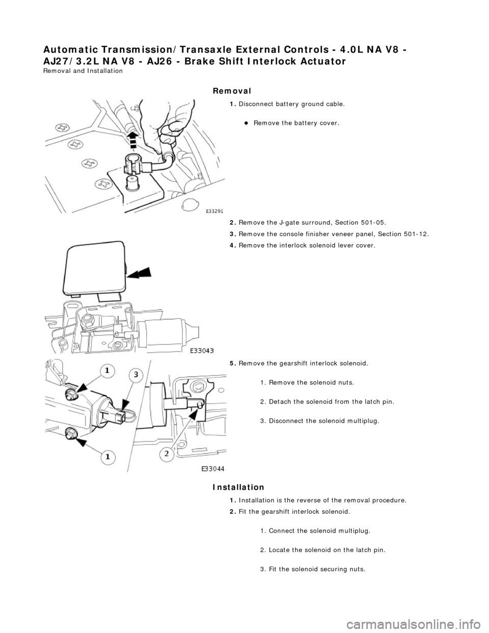
1. Disconnect battery ground cable.
Remove the battery cover.
2. Remove the J-gate surround, Section 501-05.
3. Remove the console finisher ve neer panel, Section 501-12.
4. Remove the interlock so lenoid lever cover.
5. Remove the gearshift interlock solenoid.
1. Remove the solenoid nuts.
2. Detach the solenoid from the latch pin.
3. Disconnect the solenoid multiplug.
1. Installation is th e reverse of the re moval procedure.
2. Fit the gearshift interlock solenoid.
1. Connect the solenoid multiplug.
2. Locate the solenoid on the latch pin.
3. Fit the solenoid securing nuts.
Page 1496 of 2490

10. Remove the slide bl ock/shaft assembly.
11. Remove the gearshift interlock solenoid actuating lever.
1. Remove the actu ating lever cover.
2. Remove the actuatin g lever securing nut.
12. Remove the shift lever as sembly from the housing.
Remove the washer from the pivot shaft.
13. Disassemble the shift mechanism.
1. Remove the return spring.
2. Remove the pivot shaft nut, washer and pivot shaft.
3. Remove the pivot bracket, detent plate and washer.
Page 1497 of 2490

4. Remove the ball and spring.
14. Clean all components.
15. Reassemble the shift mechanism.
1. Apply grease and install the detent ball and spring.
2. Apply grease to the pivot bracket and install the bracket, detent plate and washer.
3. Install the pivot sh aft, washer and nut.
4. Apply grease and locate the return spring.
16. Fit the shift lever assembly to the housing.
Apply grease to the lever pivot and install the pivot
washer.
17. Install the gearshift interloc k solenoid actuating lever.
1. Secure the actu ating lever nut.
2. Fit the actuating lever cover.
18. Install the slide block / shaft assembly.
Clean the slide block and shaft.
Apply grease to the shaft.
Page 1500 of 2490

ItemPart NumberDescription
1—Gear selector lever
2—Access blank - Gear-shift interlock solenoid
3—Connector - DLS
4—Dual Linear Switch (DLS)
5—Connector - Park position switch
6—Connector - Illumination module
Page 1501 of 2490

Selector lever:
Gear selector positions are:
P Transmission mechanically locked, starting available * R Reverse gear N Neutral gear, no power to the rear wheels (starting available) D Drive gear, all 5 forward gears available (see Performance Mode Pushbutton) 4 Upshift to 4th gear only 3 Upshift to 3rd gear only 2 Upshift to 2nd gear only
Gearshift Interlock Manual Override*
The interlock system which locks the sele ctor in P and prevents the ignition key from being removed except when P is
selected, may be manually overridden in the event of an emergency.
1. 1. With the parking brake applied
2. 2. Remove the access blank using a suitable Torx bit
3. 3. Insert a small screwdriver into the vacated hole
4. 4. Push the screwdriver downwards, gently, and hold whilst simultaneously moving the selector from P towards R ,
but do not engage R until the tool has been removed
5. 5. An audible warning may be heard when operation 4 is carried out
6. 6. With the selector in N and the access bl ank replaced, the vehicle may be started
Range Selection
The selector lever transmits operator demand to the transmission and TCM by means of a cable and Dual-Linear
Switch (DLS).
The lever operates the transmission assemb ly selector shaft, only for P R N D , by means of a cable. Movement of the
lever across the gate to 4, 3 and 2 positions disengages th e cable from the selector lever and engages the DLS which
controls gear selection electronically.
Gear selector module:
Provides illumination of the decal relevant to the gear sele cted. This information is provided by CAN from the TCM. Illuminates the security system Active LED on the gear selector surround, in response to an output from the BPM.
Transmission Switches
Performance Mode Pushbutton
7—Connector - Climate control
8—Solenoid - Gear selector
9—Security system Active LED
Page 1502 of 2490

The performance mode pushbutton:
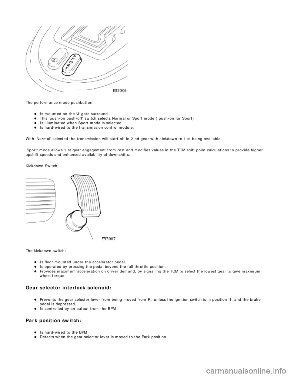
Is mounted on the 'J' gate surround. This 'push-on push-off' swit ch selects Normal or Sport mode ( push-on for Sport) Is illuminated when Sport mode is selected. Is hard-wired to the transmission control module.
With 'Normal' selected the transmissi on will start off in 2 nd gear with kickdown to 1 st being available.
'Sport' mode allows 1 st gear en gagement from rest and modifies values in the TCM shift point calculations to provide higher
upshift speeds and enhanced availability of downshifts.
Kickdown Switch
The kickdown switch:
Is floor mounted under th e accelerator pedal. Is operated by pressing the pedal beyond the full throttle position. Provides maximum acceleration on driver demand, by signalling the TCM to select the lowest gear to give maximum
wheel torque.
Gear selector interlock solenoid:
Prevents the gear selector lever from being moved from P , unless the ignition switch is in position II, and the brake
pedal is depressed.
Is controlled by an output from the BPM
Park position switch:
Is hard-wired to the BPM Detects when the gear selector lever is moved to the Park position
Page 1504 of 2490

Automatic Transmission/Transaxle External Controls - 4.0L SC V8 - AJ26 -
External Controls
Diagnosis and Testing
Problem Solving - Transmission Shift
Quick Reference Fault Chart
Special Tool(s)
Digital multimeter
Generic scan tool
SymptomPossible SourcesAction
Shift stuck in P Selector cable seized
*GO to 44.15.08
*
Interlock solenoid not operating
*GO to PDU
*
Interlock latch seized
Transmission faulty
*
*Mechanical check
*
Operator sequence error
*Correct the sequence
*
Vehicle rolls on P Incorrect cable adjustment
*GO 44.15.07
*
Faulty parking pawl (transmission internal)
*Mechanical check
*
R does not engageIncorrect cable adjustment
*GO to 44.15.07
*
Transmission fluid level incorrect
*GO to 44.24.02
*
N not achievedIncorrect cable adjustment
Transmission faulty
*
*GO to 44.15.07
*
D does not engageIncorrect cable adjustment *GO to 44.15.07
*
Transmission fluid level incorrect
*GO to 44.24.02
*
Transmission faulty
*Mechanical check
*
Lower ratios will not holdExcessive engine temperature
DLS fault
*
*GO to PDU
*
Shift lever position not visually correctIncorrect DLS adjustment
*GO to 44.15.07
*
Shift lever has no effect upon the
transmission and resistance cannot be
feltCable disconnected or broken
Transmission selector problem
Shift lever drive pin adrift
*
*
*Mechanical check
*
Shift lever position not align correctly
following manual selection of lower
ratiosSliding block drive pin displaced - following road debris contact
*Mechanical check. Renew the selector if
damaged, or re-align the drive pin and
sliding block
*
Shift lever detent indistinct in 3
causing poor locationDLS detent fault
*GO to Renew the DLS
*
Shift may be moved from P without
brake pedal operationInterlock latch fault
*Mechanical check
*
Solenoid permanently activated
*GO to PDU
*
Engine may be started in positions
other than P or N Incorrect cable adjustment
DLS fault
*
*GO to 44.15.07
*
Shift lever vibrationLoose selector assembly
Cable isolation fault
*
*Mechanical check
*
Noise / rattle from 'J' gateDebris in the mechanism
*Clean
*
Worn 'J' gate track gasket
allowing lever and moulding to
contact
*GO to 44.15.05
*
Page 1511 of 2490

Automatic Transmission/Transaxle External Contro ls - 4.0L SC V8 - AJ26 -
Brake Shift Interlock Actuator
Removal and Installation
Removal
Installation
1.
Disconnect the vehicle battery ground lead.
2. Remove the J-gate surround, Section 501-05.
3. Remove the console finisher ve neer panel, Section 501-12.
4. Remove the interlock so lenoid lever cover.
5. Remove the gearshift interlock solenoid.
1. Remove the (2) solenoid nuts.
2. Detach the solenoid from the latch pin.
3. Disconnect the solenoid multiplug.
1. Installation is th e reverse of the re moval procedure.
2. Refer to the illustration.
Page 1784 of 2490

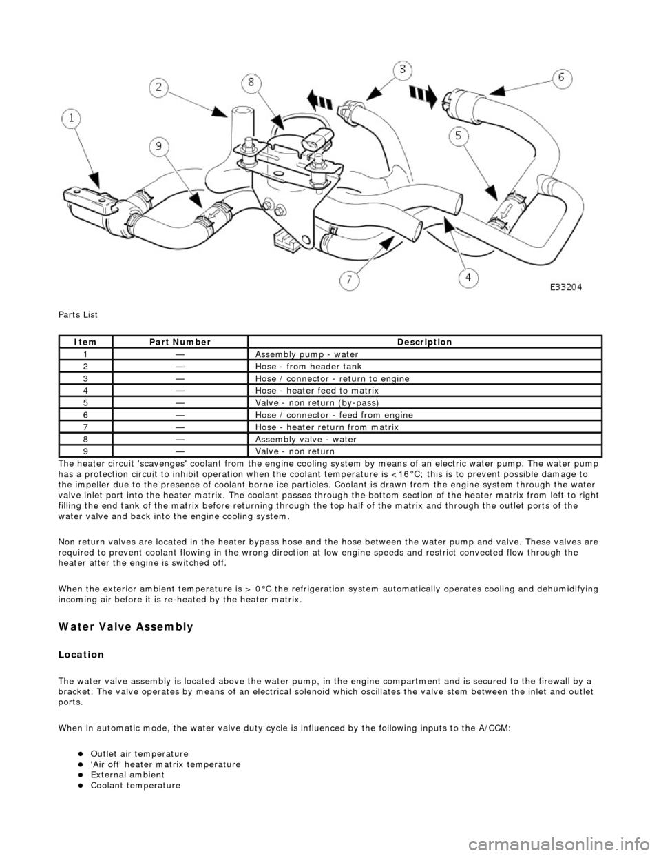
Parts List
The heater circuit 'scavenges' coolant from the engine cooling system by mean s of an electric water pump. The water pump
has a protection circuit to inhibit operation when the coolant temperature is <16°C; this is to prevent possible damage to
the impeller due to the presence of coolant borne ice particles. Coolant is drawn from the en gine system through the water
valve inlet port into the heater matrix. The coolant passes thro ugh the bottom section of the heater matrix from left to right
filling the end tank of the matrix before returning through the top half of the ma trix and through the outlet ports of the
water valve and back into the engine cooling system.
Non return valves are located in the heat er bypass hose and the hose between the water pump and valve. These valves are
required to prevent coolant flowing in th e wrong direction at low engine speeds and restrict convected flow through the
heater after the engine is switched off.
When the exterior ambient temperature is > 0°C the refrigerat ion system automatically operates cooling and dehumidifying
incoming air before it is re -heated by the heater matrix.
Water Valve Assembly
Location
The water valve assembly is located above the water pump, in the engine compartmen t and is secured to the firewall by a
bracket. The valve operates by means of an electrical solenoid which oscillates the valve stem between the inlet and outlet
ports.
When in automatic mode, the water valve duty cycle is influenced by the following inputs to the A/CCM:
Outlet air temperature 'Air off' heater matrix temperature External ambient Coolant temperature
ItemPart NumberDescription
1—Assembly pump - water
2—Hose - from header tank
3—Hose / connector - return to engine
4—Hose - heater feed to matrix
5—Valve - non return (by-pass)
6—Hose / connector - feed from engine
7—Hose - heater return from matrix
8—Assembly valve - water
9—Valve - non return