lamp JAGUAR X308 1998 2.G Repair Manual
[x] Cancel search | Manufacturer: JAGUAR, Model Year: 1998, Model line: X308, Model: JAGUAR X308 1998 2.GPages: 2490, PDF Size: 69.81 MB
Page 1011 of 2490
Supercharger Cooling - Water Pump
Re
moval and Installation
Remov
al
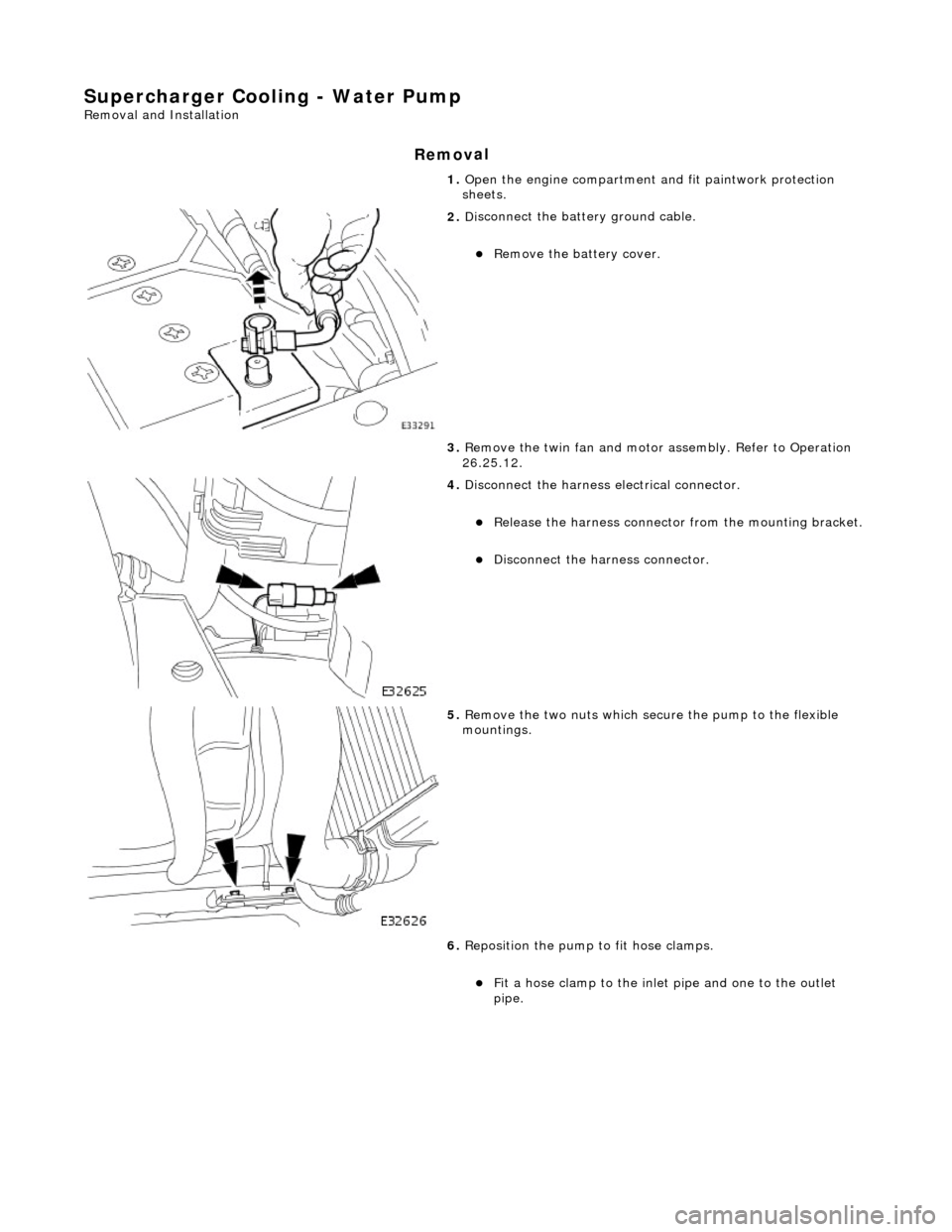
1.
O
pen the engine compartment and fit paintwork protection
sheets.
2. Di
sconnect the batt
ery ground cable.
R
emove the battery cover.
3. Remove the twin fan and motor assembly. Refer to Operation
26.25.12.
4. Disc
onnect the harness electrical connector.
R
elease the harness connector from the mounting bracket.
Disc
onnect the harness connector.
5. R
emove the two nuts which secure the pump to the flexible
mountings.
6. Reposition the pump to fit hose clamps.
Fi
t a hose clamp to the inlet pipe and one to the outlet
pipe.
Page 1012 of 2490
In
stallation
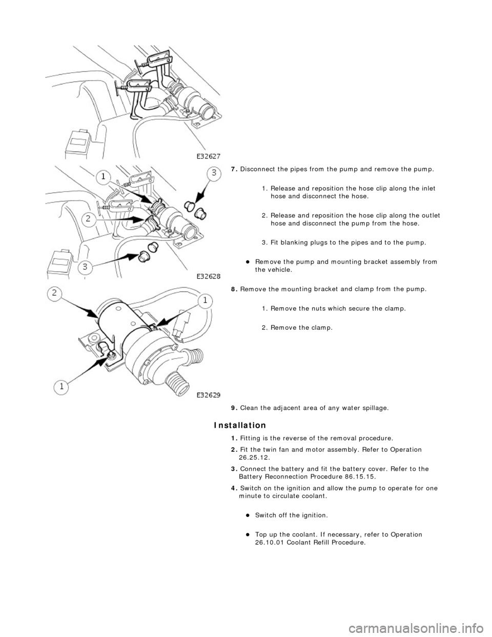
7.
Disc
onnect the pipes from the
pump and remove the pump.
1. Release and reposition th e hose clip along the inlet
hose and discon nect the hose.
2. Release and reposition the hose clip along the outlet
hose and disconnect th e pump from the hose.
3. Fit blanking plugs to the pipes and to the pump.
Remove t
he pump and mounting bracket assembly from
the vehicle.
8. Remove the moun
ting bracket and clamp from the pump.
1. Remove the nuts which secure the clamp.
2. Remove the clamp.
9. Clean the adjacent area of any water spillage.
1. Fitting is the reverse of the removal procedure.
2. Fit the twin fan and motor assembly. Refer to Operation
26.25.12.
3. Connect the battery and fit the battery cover. Refer to the
Battery Reconnection Procedure 86.15.15.
4. Switch on the ignition and allow the pump to operate for one
minute to circulate coolant.
Swit ch
off the ignition.
Top up th
e coolant
. If ne
cessary, refer to Operation
26.10.01 Coolant Refill Procedure.
Page 1022 of 2490
(ECT) se
nsor
Blocked part-load breather
(s
ervice action S474)
Injec
t
or leak
Engine stalls
soon
after start
F
u
el pump relay
ECM relay Thr
o
ttle contaminated
CMP/CKP sen
s
or
synchronization malfunction
Harness Fuel
pump
MAF
s
ensor malfunction
Engine coolan
t
temperature
(ECT) sensor
Fue l
lines
Air leakage Fu
el pressure regulator
F
o
r fuel pump relay tests,
GO to Pinpoint Test E.
.
F or ECM
relay tests,
REFER to Section 303
-14 Elec tronic En
gine
Controls.
Check bull etins for throttl
e cleaning procedure. For
CMP/CKP sensor tests,
REFER to Section 303
-14 Elec tronic En
gine
Controls.
Chec k fu
el pressure,
REFER to Section 310
-00 Fu
el System
- Ge
n
eral
Informati
o
n
.
F or MAF sensor and
ECT sensor tests,
REFER to Section 303
-14 Electronic En
gine
Controls.
For fuel l
ine information,
REFER to Section 310
-01
Fuel Tank and Lines
.
F or i
ntake system information,
REFER to Section 303
-1 2
Intake Air Distribution
and F
ilt
ering
.
F o
r fuel pressure regulato
r check, GO to Pinpoint
Test D.
.
Engine h e
sitates/poor
acceleration
Fue l
pump
Exhaus
t gas
recirculation
(EGR)
Air leakage Stop lamp swi t
ch
Throttl
e
sensors
Throttl
e
motor
Spark plugs
fouled
Check f
o
r water ingress into
spark plug wells
Ignition coil fail
ure(s)
HT sho
rt to ground (tracking)
check rubber
boots for
cracks/damage
ECM failu r
e
Chec
k fu
el pressure,
REFER to Section 310
-00 Fu
el System
- Ge
n
eral
Informati
o
n
.
F o
r EGR information,
REFER to Section 303
-08 En gin
e Emission
Control.
F or i
ntake system information,
REFER to Section 303
-1 2
Intake Air Distribution
and F
ilt
ering
.
F or stop l
amp switch in
formation, refer to the
wiring diagrams. For throttle position sensor and throttle motor relay tests,
REFER to Section 303
-14 Elec tronic En
gine
Controls.
For ign i
tion system,
REFER to Section 303
-07 En
gine Ignition
.
Contact dealer techn i
cal
support for advice on
possible ECM failure.
Engine ba ckfiresFuel
pump
Air leakage MAF s
e
nsor
HO2 sensors Spark plugs
Check fo
r water ingress into
spark plug wells
HT short to ground (tracking) check rubber
boots for
cracks/damage
Ignition coil fail
ure(s)
Chec
k fu
el pressure,
REFER to Section 310
-00 Fu
el System
- Ge
n
eral
Informati
o
n
.
F or i
ntake system information,
REFER to Section 303
-1 2
Intake Air Distribution
and F
ilt
ering
.
For MAF and HO2
sensor circuit tests,
REFER to Section 303
-14 Electronic En
gine
Controls.
For igni
tion system,
REFER to Section 303
-07 En
gine Ignition
.
Engine
s
urges
Air leakage Fue
l
pump
Stop lamp swi
t
ch
MAF s
e
nsor
Harness Throttl
e
sensors
Throttl
e
motor
Spark plugs
Check fo
r water ingress into
spark plug wells
HT sho rt to ground (tracking)
check rubber
boots for
cracks/damage
ECM failu r
e
F
or i
ntake system information,
REFER to Section 303
-1 2
Intake Air Distribution
and F
ilt
ering
.
Chec k fu
el pressure,
REFER to Section 310
-00 Fu
el System
- Gen
e
ral
Informati
o
n
.
F or stop l
amp switch in
formation, refer to the
wiring diagrams. For MAF se nsor, throttle position
sensor and throttle motor relay tests,
REFER to Section 303
-14 Elec tronic En
gine
Controls.
For ign i
tion system,
REFER to Section 303
-07 En
gine Ignition
.
Contact dealer techn i
cal
support for advice on
possible ECM failure.
Page 1037 of 2490
Fuel Ch
arging and Controls
- Fuel Injector4.0L NA V8 - AJ27/3.2L NA V8 -
AJ26
Re
moval and Installation
Remov
al
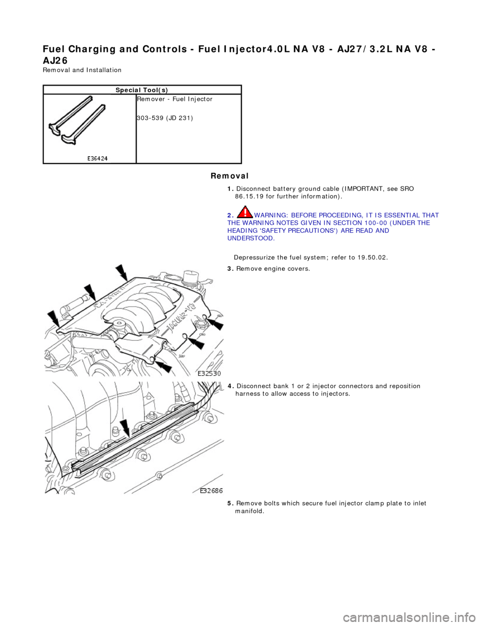
S
pecial Tool(s)
R
emover - Fuel Injector
303-539 (JD 231)
1. Disconnect battery ground cable (IMPORTANT, see SRO
86.15.19 for further information).
2. WARNING: BEFORE PROCEEDING, IT IS ESSENTIAL THAT
THE WARNING NOTES GIVEN IN SECTION 100-00 (UNDER THE
HEADING 'SAFETY PRECAUTIONS') ARE READ AND
UNDERSTOOD.
Depressurize the fuel sy stem; refer to 19.50.02.
3. R
emove engine covers.
4. Di
sconnect bank 1 or 2 inject
or connectors and reposition
harness to allow access to injectors.
5. Remove bolts which secure fuel injector clamp plate to inlet
manifold.
Page 1110 of 2490
2.2. Cruise
3. 3. Mechanica l
guard
4. 4. Fixed idle
5. 5. Redundancy
6. 6. Full authority
7. 7. Engine shut-down
Normal mode occurs when the EC M uses the mechanical and monitoring arrangem ent of the throttle valve to control throttle
opening. The ECM does not permit driver demand to be exceeded but it can be restricted to allow for such features as
stability / traction control, or engine power limitation.
The ECM determines engine idle speed by controlling the throttle valve motor to vary the blade angle between the non-
adjustable preset limits of the mechanic al guard and the throttle valve motor.
Cruise mode is engaged as a result of the ECM calculating and controlling the required throttle valve opening via the
vacuum system. When the driver releases the throttle pedal, the input shaft disengages from the mechanical guard or the
vacuum actuator pulls the guard away from th e throttle valve. The throttle pedal will feel light should it be pushed again to
accelerate (pressing the pedal further will re-engage the input shaft with the mechanical guard and restore normal feel).
The ECM utilizes sensors to monitor the relative positions of the mechanical guard and throttle valve and adjusts them to
maintain the set cruise speed.
Mechanical guard mode permits full mechanical operation of the throttle if the ECM detects that a problem has been
encountered with the throttle valve position sensor, dc motor, associated harnesses / connecto rs or the ECM.
Fixed idle mode occurs when any two of the three sensors (two input shaft sensors and the mechanical guard sensor) fail.
The ECM will assume values which represent a blade angl e of approximately 2,5° and 1200 rpm (unloaded) maximum
engine speed.
Redundancy mode occurs when any one of the three sensors (two input shaft sensors and the mechanical guard sensor)
fails. The operational pair will be deemed to be safe to co ntinue without intervention, but cruise will be inhibited.
Full authority mode is invoked when a mech anical guard failure occurs which indicates that the guard is stuck fully open.
The red warning lamp will be lit and road speed will be li mited to 120 kph.
Engine shut-down mode will occur followin g multiple failures, such as mechanical guard mode following full authority mode
(or vice versa) or the throttle blade sticks.
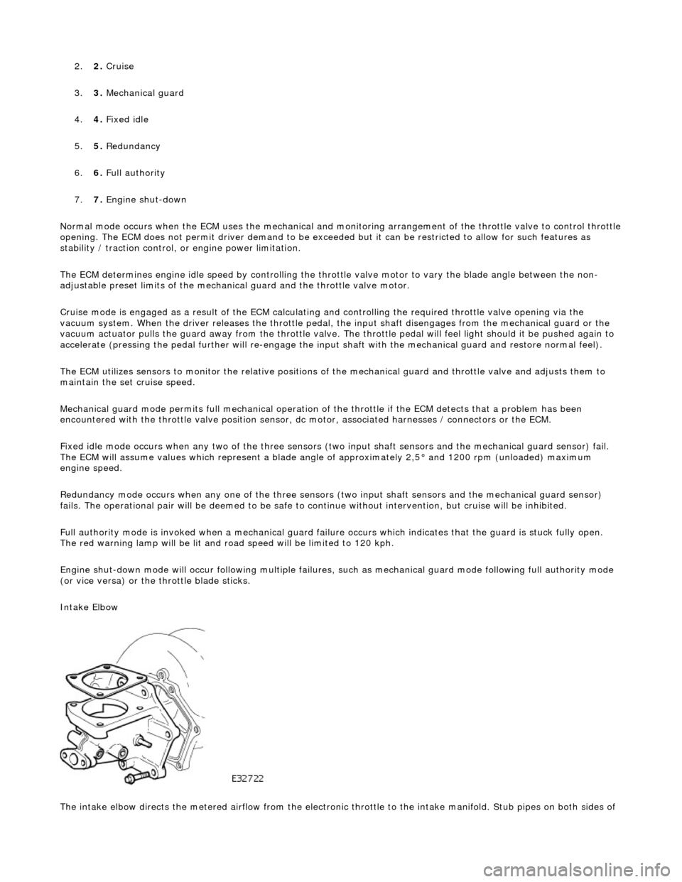
Intake Elbow
The intake elbow directs the metered airflow from the electronic throttle to the intake manifold. Stub pipes on both sides of
Page 1115 of 2490
is at
tached to the three mounting bosses between the V of the cylinder block
has a fil
led for life inte
rnal lubrication system
is po
sitively aligned with the drive
belt by a doweled mounting bracket
C
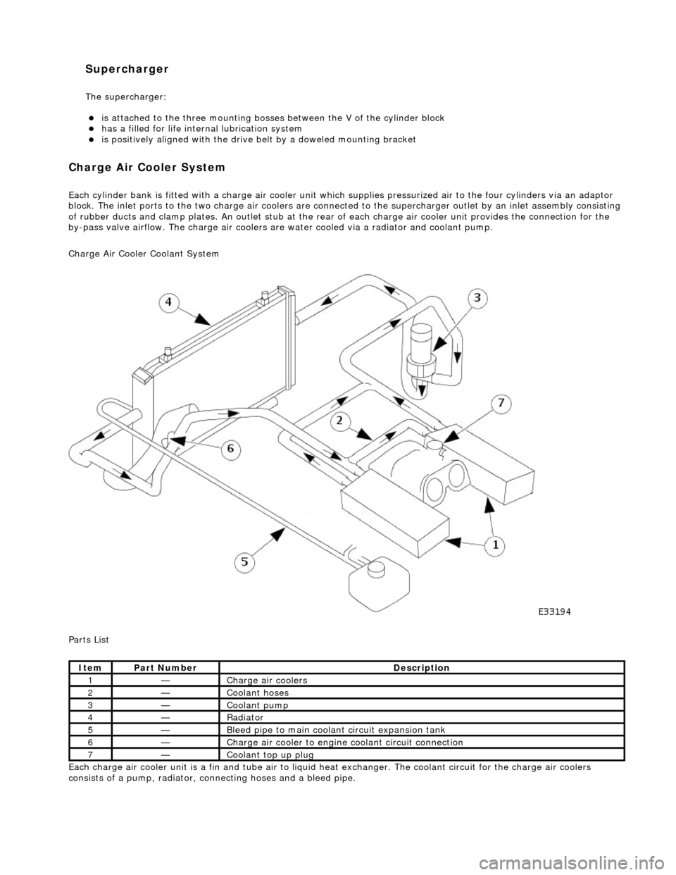
harge Air Cooler System
Each cyl
inder bank is fitted with a charge air cooler unit wh
ich supplies pressurized air to the four cylinders via an adaptor
block. The inlet ports to the tw o charge air coolers are connected to the supercharger outlet by an inle t assembly consisting
of rubber ducts and clamp plates . An outlet stub at the rear of each charge air cooler unit provides the connection for the
by-pass valve airflow. The charge air coolers ar e water cooled via a radiator and coolant pump.
Charge Air Cooler Coolant System
Parts List
Each charge air cooler unit is a fin and tube air to liquid heat exchanger. The coolant circuit for the charge air coolers
consists of a pump, ra diator, connecting hoses and a bleed pipe.
It
em
Par
t Number
De
scription
1—Charge air cool
ers
2—Coo
lant hoses
3—Coo
lant pump
4—Radi
ator
5—Ble
ed pipe to main coolant circuit expansion tank
6—Charge air cooler to en
gine
coolant circuit connection
7—Coo
lant top up plug
Supercharger
The supe
rcharger:
Page 1130 of 2490
Intake Air Distribution and Filtering - Supercharger Outlet Pipe
Remo
val and Installation
Remov
a
l
1.
Re
move air cleaner cover / intake
assembly; refer to 19.10.30.
2. Drain radiator coolant; refer to operation (SC) 26.10.01.
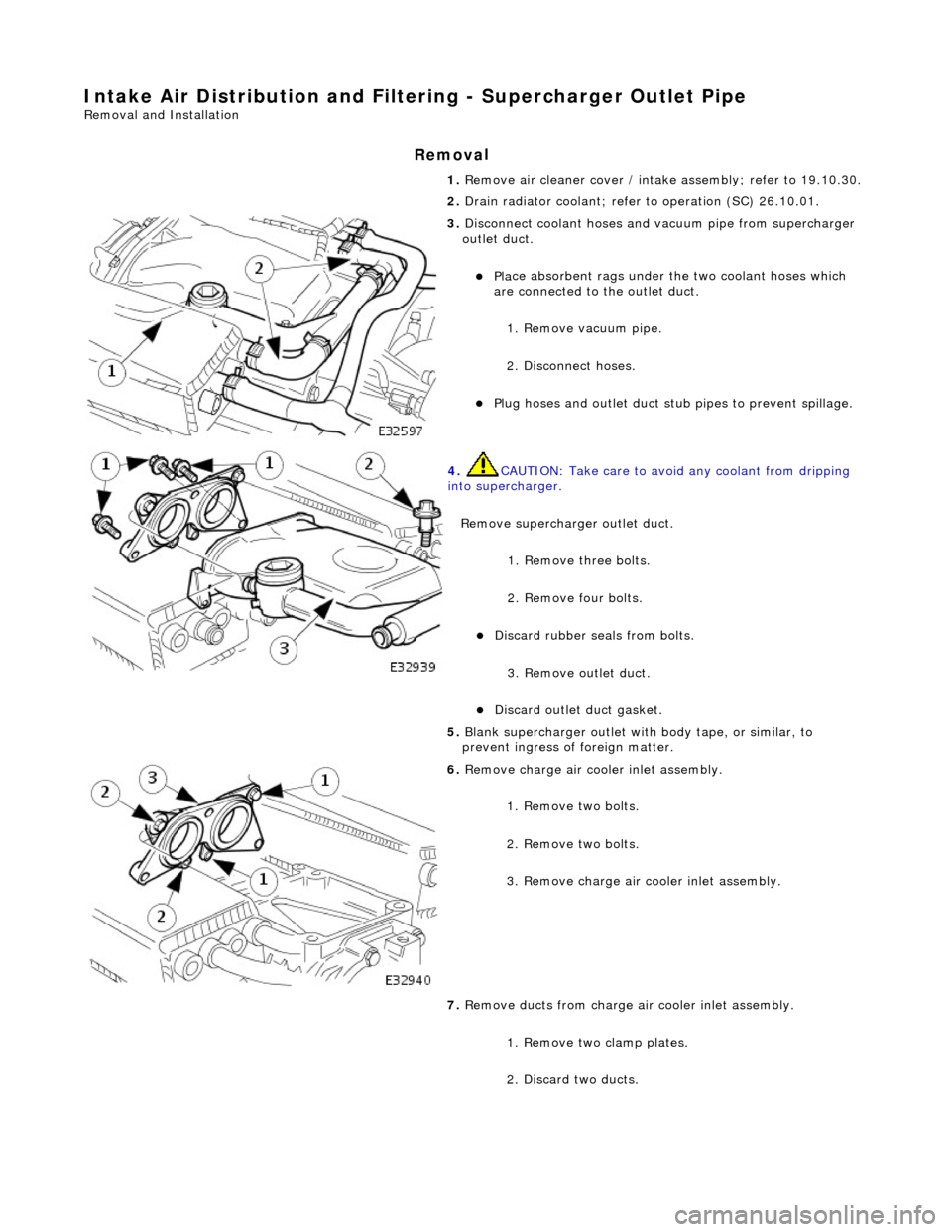
3. Disc
onnect coolant hoses and vacuum pipe from supercharger
outlet duct.
Pl a
ce absorbent rags under
the two coolant hoses which
are connected to the outlet duct.
1. Remove vacuum pipe.
2. Disconnect hoses.
Plu g
hoses and outlet duct stub pipes to prevent spillage.
4. CAUTIO
N: Take care to avoi
d any coolant from dripping
into supercharger.
Remove supercharger outlet duct. 1. Remove three bolts.
2. Remove four bolts.
Di
scard rubber seals from bolts.
3. Remove outlet duct.
Discard ou
tlet duct gasket.
5.
Bla
nk supercharger outlet with
body tape, or similar, to
prevent ingress of foreign matter.
6. Remove charge air c oo
ler inlet assembly.
1. Remove two bolts.
2. Remove two bolts.
3. Remove charge air cooler inlet assembly.
7. Remove ducts from charge air cooler inlet assembly.
1. Remove two clamp plates.
2. Discard two ducts.
Page 1131 of 2490
I
nstallation
8.
Cl
ean all relevant parts and mating faces.
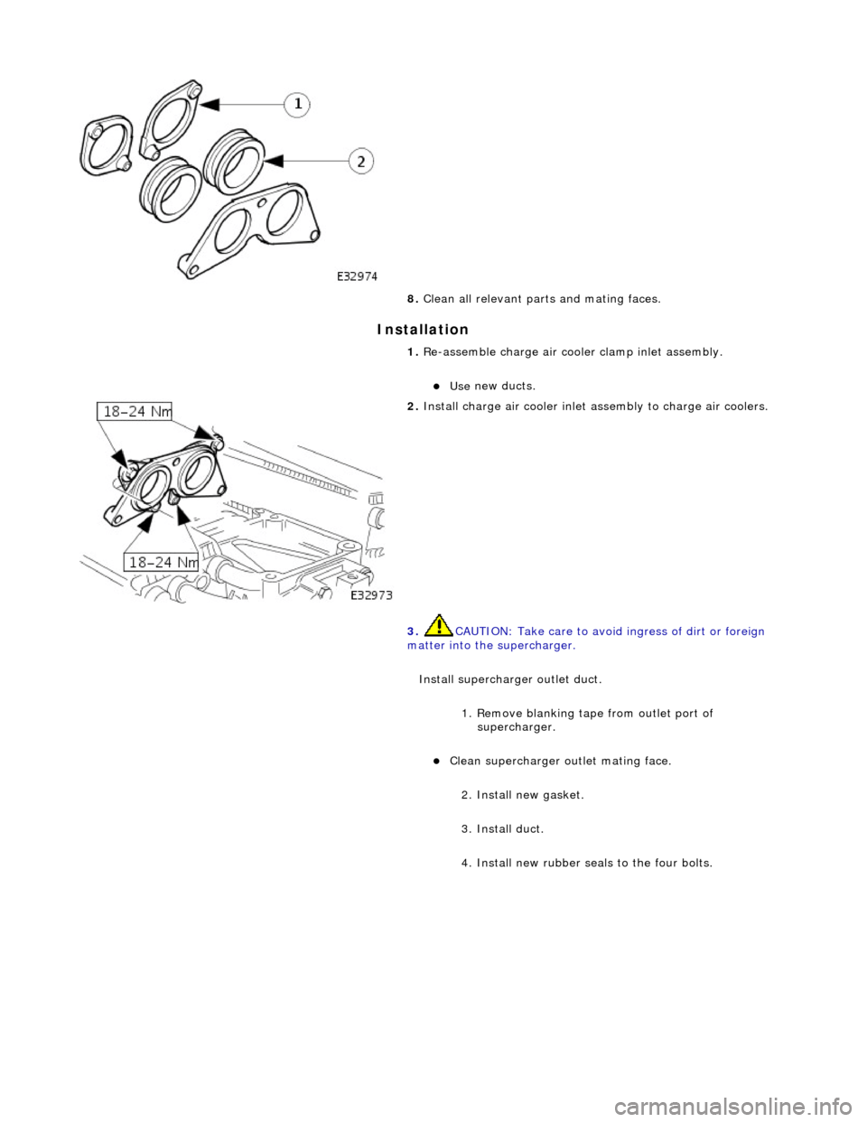
1. Re-assemble charge air cooler clamp inlet assembly.
Use
new ducts.
2. Install ch
arge air cooler inlet as
sembly to charge air coolers.
3. CAUTION: Take care to avoid ingress of dirt or foreign
matter into the supercharger.
Install supercharger outlet duct. 1. Remove blanking tape from outlet port of
supercharger.
Cl
ean supercharger outlet mating face.
2. Install new gasket.
3. Install duct.
4. Install new rubber seals to the four bolts.
Page 1192 of 2490
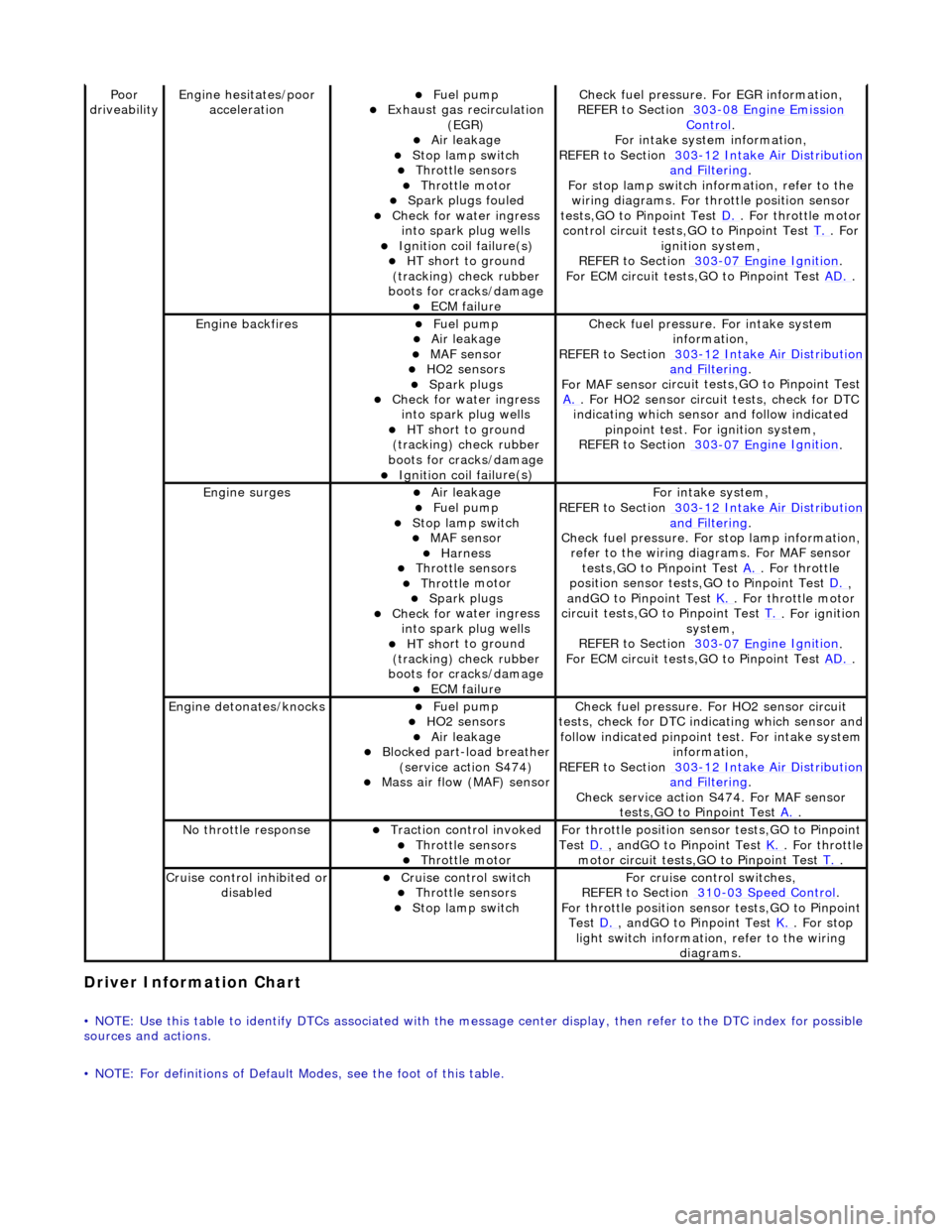
Driver Information
Chart
•
NOTE: Use this table to identify DTCs associated with the me
ssage center display, then refer to the DTC index for possible
sources and actions.
• NOTE: For definitions of Default Modes, see the foot of this table.
Poor
dr iveabilityEngine h e
sitates/poor
acceleration
Fue l
pump
Exhaus
t gas
recirculation
(EGR)
Air leakage Stop lamp swi t
ch
Throttl
e
sensors
Throttl
e
motor
Spark
plugs
fouled
Check f
o
r water ingress
into spark plug wells
Ignition coil fail
ure(s)
HT sh
o
rt to ground
(tracking) check rubber
boots for cracks/damage
ECM failu r
e
Check f
u
el pressure. For EGR information,
REFER to Section 303
-08 En gin
e Emission
Control.
F or i
ntake system information,
REFER to Section 303
-1 2
Intake Air Distribution
and F
ilt
ering
.
F or stop l
amp switch in
formation, refer to the
wiring diagrams. For throttle position sensor
tests,GO to Pinpoint Test D.
. Fo
r throttle motor
control circuit tests,GO to Pinpoint Test T.
. For
igni t
ion system,
REFER to Section 303
-07 En
gine Ignition
.
F or ECM
circuit tests,GO to Pinpoint Test
AD.
.
Engine backfiresFuel
pump
Air leakage MAF se
nsor
HO2 sensors
Spark plugs Check fo
r water ingress
into spark plug wells
HT sh o
rt to ground
(tracking) check rubber
boots for cracks/damage
Ignition coil fail
ure(s)
Chec
k fu
el pressure. For intake system
information,
REFER to Section 303
-12
Intake Air Distribution
and Filt
ering
.
F or MAF sensor ci
rcuit test
s,GO to Pinpoint Test
A.
. F or HO2 sensor
circui
t tests, check for DTC
indicating which sensor and follow indicated pinpoint test. For ignition system,
REFER to Section 303
-07 En
gine Ignition
.
Engine
s
urges
Air leakage
Fuel
pump
Stop lamp swit
ch
MAF s
e
nsor
Harness Throttl
e
sensors
Throttl
e
motor
Spark plugs
Check fo
r water ingress
into spark plug wells
HT sh o
rt to ground
(tracking) check rubber
boots for cracks/damage
ECM failu r
e
Fo
r
intake system,
REFER to Section 303
-1 2
Intake Air Distribution
and Filt
ering
.
Check fu
el pressure. For
stop lamp information,
refer to the wiring diagrams. For MAF sensor tests,GO to Pinpoint Test A.
. Fo
r throttle
position sensor tests,GO to Pinpoint Test D.
,
a n
dGO to Pinpoint Test
K.
. Fo
r throttle motor
circuit tests,GO to Pinpoint Test T.
. For ig
nition
system,
REFER to Section 303
-07 En
gine Ignition
.
F or ECM
circuit tests,GO to Pinpoint Test
AD.
.
Engine detonates/k
nocks
Fue
l
pump
HO2 sensors
Air leakage Blocked part-load breather
(s
ervice action S474)
Mass ai
r fl
ow (MAF) sensor
Chec
k fu
el pressure. Fo
r HO2 sensor circuit
tests, check for DTC indicating which sensor and
follow indicated pinpoint test. For intake system
information,
REFER to Section 303
-1 2
Intake Air Distribution
and Filt
ering
.
Check service action S474
. For MAF sensor
tests,GO to Pinpoint Test A.
.
No t
hrottle response
Traction contr
o
l invoked
Throttl
e
sensors
Throttl
e
motor
Fo
r th
rottle position sensor tests,GO to Pinpoint
Test D.
, andG O to Pinpoint
Test
K.
. Fo
r throttle
motor circuit tests,GO to Pinpoint Test T.
.
Cru i
se control inhibited or
disabled
Cru i
se control switch
Throttle
sensors
Stop lamp swit
ch
For cru
i
se control switches,
REFER to Section 310
-03
Speed Control
.
For th
rottle position sensor tests,GO to Pinpoint
Test D.
, andG O to Pinpoint
Test
K.
. For s t
op
light switch information, refer to the wiring diagrams.
Page 1270 of 2490
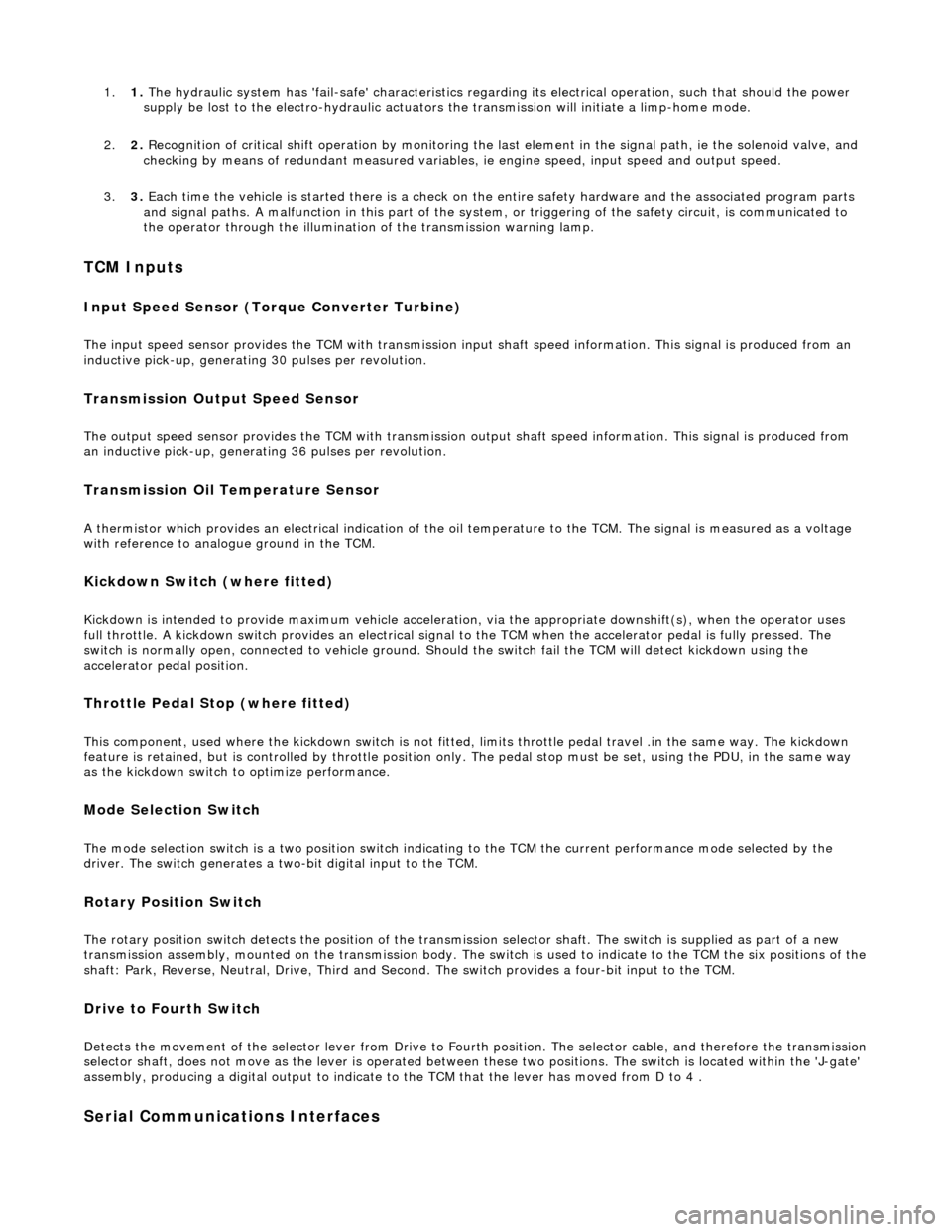
1.1. The hydraulic system has 'fail-safe' characteristics regardin g its electrical operation, such that should the power
supply be lost to the electro-hydraulic actuators the transmission will initiate a limp-home mode.
2. 2. Recognition of critical shift operation by monitoring the last element in the signal path, ie the solenoid valve, and
checking by means of redundant me asured variables, ie engine speed, input speed and output speed.
3. 3. Each time the vehicle is started there is a check on the entire safety hardware and the associated program parts
and signal paths. A malfunction in this part of the system, or triggering of the safety circuit, is communicated to
the operator through the illumination of the transmission warning lamp.
TCM Inputs
Input Speed Sensor (Torque Converter Turbine)
The input speed sensor provides the TCM with transmission inpu t shaft speed information. This signal is produced from an
inductive pick-up, generating 30 pulses per revolution.
Transmission Output Speed Sensor
The output speed sensor provides the TCM with transmission ou tput shaft speed information. This signal is produced from
an inductive pick-up, generati ng 36 pulses per revolution.
Transmission Oil Temperature Sensor
A thermistor which provides an electrical indication of the oi l temperature to the TCM. The signal is measured as a voltage
with reference to analog ue ground in the TCM.
Kickdown Switch (where fitted)
Kickdown is intended to provide maximum vehicle acceleration , via the appropriate downshift(s), when the operator uses
full throttle. A kickdown switch provides an electrical signal to the TCM wh en the accelerator pedal is fully pressed. The
switch is normally open, connected to vehicle ground. Should the switch fail the TCM will detect kickdown using the
accelerator pedal position.
Throttle Pedal Stop (where fitted)
This component, used where the kickdown switch is not fitted, limits throttle pedal travel .in the same way. The kickdown
feature is retained, but is controlled by throttle position only. The pedal stop must be set, using the PDU, in the same way
as the kickdown switch to optimize performance.
Mode Selection Switch
The mode selection switch is a two position switch indicati ng to the TCM the current performance mode selected by the
driver. The switch generates a tw o-bit digital input to the TCM.
Rotary Position Switch
The rotary position switch detects the position of the transmis sion selector shaft. The switch is supplied as part of a new
transmission assembly, mounted on the transmission body. The swit ch is used to indicate to the TCM the six positions of the shaft: Park, Reverse, Neutral, Drive, Third and Second. The switch provides a four-bit input to the TCM.
Drive to Fourth Switch
Detects the movement of the selector lever from Drive to Fourth position. The selector cable, and therefore the transmission selector shaft, does not move as the lever is operated between these two positions. The switch is located within the 'J-gate'
assembly, producing a digital output to indicate to the TCM that the lever has moved from D to 4 .
Serial Communications Interfaces