lamp JAGUAR X308 1998 2.G Service Manual
[x] Cancel search | Manufacturer: JAGUAR, Model Year: 1998, Model line: X308, Model: JAGUAR X308 1998 2.GPages: 2490, PDF Size: 69.81 MB
Page 840 of 2490

Wipe the drain plug and install it to the oil pan to prevent
oil dripping.
Move the oil bowser away from the vehicle.
10. Remove the oil pan.
1. Remove the eighteen bolt s which secure the oil pan
to the oil pan body.
2. Remove the oil pan.
3. Remove the gasket from the oil pan body assembly.
11. NOTE: Place a suitable container underneath filter to prevent
oil spillage.
Using the special tool, remove the oil filter.
12. Remove the oil pressure switch.
For additional information, refer to Oil Pressure Switch
- in this
section.
13. Remove the crankshaft position sensor.
1. Remove the bolt which secures the crankshaft position sensor to the flywheel housing.
2. Remove the access grommet from the housing.
Remove the sensor and allow it to hang free under the
engine.
Release the harness clips from the oil pan body.
14. Remove the bolt which secures the transmission cooler pipes
and remove the clamping bracket.
Page 846 of 2490

Tighten the oil filter to 15-18 Nm.
12. Install the crankshaft position sensor.
1. Install the sensor to the flywheel housing and fit the
securing bolt. Tighten to 8-12 Nm.
2. Install the access grommet to the housing.
Connect the harness clips to the oil pan body.
13. Install the four bolts (two each side) which secure the
exhaust downpipes to the oil pan body and transmission
casing.
14. Install the air conditioning compressor.
Locate the compressor onto the lower dowel.
Tighten the upper securing bolts.
Install and tighten the lower securing bolts to 18-24 Nm.
Tighten the upper securing bolts to 18-24 Nm.
15. Position the transmission cooler pipes and the clamping
bracket. Install the bolt to secu re the clamp and tighten to 7-9
Nm.
Page 850 of 2490

Using the special tool, remove the oil filter.
19. Remove the oil pressure switch.
For additional information, refer to Oil Pressure Switch
- in this
section.
20. Remove the crankshaft position sensor.
1. Remove the bolt which secures the crankshaft position sensor to the flywheel housing.
2. Remove the access grommet from the housing.
Remove the sensor and allow it to hang free under the
engine.
Release the harness clips from the oil pan body.
21. Remove the bolt which secures the transmission cooler pipes
and remove the clamping bracket.
22. Release the air conditioning compressor.
Remove the lower securing bolts.
Loosen, but do not remove, th e upper securing bolts.
Release the compressor from the lower dowel.
23. Remove the four bolts (two each side) which secure the
exhaust downpipes to the oil pan body.
Page 857 of 2490

Install and tighten the lower securing bolts to 18-24 Nm.
Tighten the upper securing bolts to 18-24 Nm.
16. Position the transmission cooler pipes and the clamping
bracket. Install the bolt to secu re the clamp and tighten to 7-9
Nm.
17. Connect the oil cooler pipes to the oil pan body assembly
(vehicles with engine oil cooler).
1. Remove the blanking plugs and install new O-ring seals.
2. Connect the oil cooler pipes.
3. Install the clamp and bolt which secures the oil cooler pipes. Tighten to 18-24 Nm.
18. Install the front cr ossmember. Refer to Operation 76.10.05.
19. Position the generator cooling duct to the oil pan body and
install the two bolts.
20. Install the undert ray. Refer to Operation 76.22.90.
21. Install both front wheel and tyre assemblies. Refer to
Operation 74.20.05.
22. Install the timing cover and al l associated components, as
detailed in Operation 12.65.01. Do not refill the cooling system
at this stage.
Page 900 of 2490

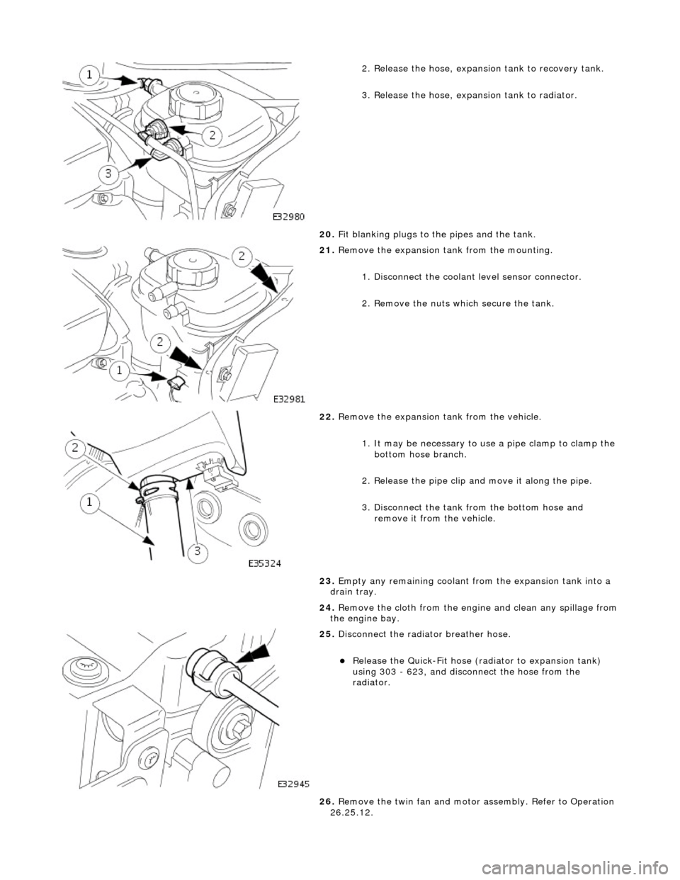
2. Release the hose, expansion tank to recovery tank.
3. Release the hose, expansion tank to radiator.
20. Fit blanking plugs to the pipes and the tank.
21. Remove the expansion tank from the mounting.
1. Disconnect the coolant level sensor connector.
2. Remove the nuts which secure the tank.
22. Remove the expansion tank from the vehicle.
1. It may be necessary to us e a pipe clamp to clamp the
bottom hose branch.
2. Release the pipe clip an d move it along the pipe.
3. Disconnect the tank from the bottom hose and remove it from the vehicle.
23. Empty any remaining coolant from the expansion tank into a
drain tray.
24. Remove the cloth from the engine and clean any spillage from
the engine bay.
25. Disconnect the radiator breather hose.
Release the Quick-Fit hose (radiator to expansion tank)
using 303 - 623, and disconnect the hose from the
radiator.
26. Remove the twin fan and motor assembly. Refer to Operation
26.25.12.
Page 904 of 2490

41. Raise the vehicle on the ramp.
42. Drain the engine oil.
1. Position the waste oil bowser.
2. Remove the sump drain pl ug and drain the engine oil.
Wipe the drain plug and refit it to the sump to prevent oil
dripping.
Move the oil bowser away from the vehicle.
43. Move the front muffler forwar d to allow the intermediate
mufflers to be displaced.
Slacken the clamps (left-hand and right-hand sides),
catalytic converter to front muffler.
44. Slacken the clamps (left-han d and right-hand sides),
intermediate mufflers to front muffler.
45. Remove the front muffler.
Disconnect the front muffler from the intermediate
mufflers and then from the downpipe catalytic converters.
46. Remove the downpipe catalytic converters.
Page 905 of 2490

Remove the bolts which secure the downpipe to the lower
mounting bracket.
Remove the downpipe assembly.
Repeat the above operations for the other downpipe
catalytic converter.
47. Remove the two bolts which secure each mounting bracket to
the bell housing and remove the brackets.
48. Disconnect the driveshaft (propshaft) flange from the
transmission output flange.
Remove the three bolts which secure the flange. Rotate
the shaft for access to each bolt.
Disconnect the shaft and reposition it to the side.
49. Remove the securing bolt and disconnect the ground lead
from the transmission casing.
50. Disconnect the oil cooler pi pes (where fitted) from the
engine.
1. Remove the bolt which secures the pipe clamping
plate. Remove the clamping plate.
2. Place a drain tray beneat h the pipes and disconnect
Page 915 of 2490

Connect
the front muffler to
the intermediate muffler,
noting the alignment of the indicator rings.
W
ith the front muffler positioned correctly, tighten the
clamps (left-hand and right-hand sides) to the catalytic
converter.
21
.
Tighten the clamps (left-hand and right-hand sides),
intermediate mufflers to front muffler.
22
.
Tighten the downpipe bracket se curing bolts to the correct
torque
23
.
Connect the oil cooler pipes (w here fitted) to the engine.
1. Remove the blanking plugs from the pipes and from the mating unions on the engine.
2. Fit new O-ring seals to the pipes and lubricate with new engine oil.
3. Connect the pipes to the engine and fit the clamping
plate and bolt.
24. Lower the vehicle on the ramp.
25. Connect the heater and brake servo hoses.
1. Connect the heat er return hose.
2. Connect the heater feed hose and secure the locking
lever.
Page 920 of 2490

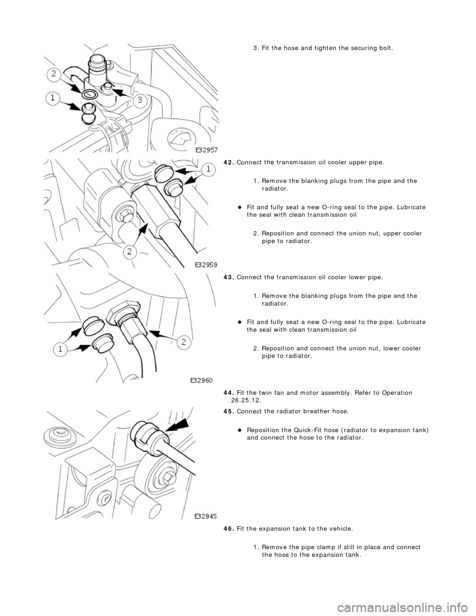
3.
Fit the hose and tighten the securing bolt.
42 . Conne
ct the transmission
oil cooler upper pipe.
1. Remove the blanking plugs from the pipe and the radiator.
Fit and
fully seat a new O-ring
seal to the pipe. Lubricate
the seal with clean transmission oil
2. Reposition and connect the union nut, upper cooler pipe to radiator.
43 . Conne
ct the transmission oil cooler lower pipe.
1. Remove the blanking plugs from the pipe and the radiator.
Fit and
fully seat a new O-ring
seal to the pipe. Lubricate
the seal with clean transmission oil
2. Reposition and connect the union nut, lower cooler
pipe to radiator.
44. Fit the twin fan and motor assembly. Refer to Operation
26.25.12.
45 . Connect
the radiator breather hose.
Re
po
sition the Quick-Fit hose (radiator to expansion tank)
and connect the hose to the radiator.
46. Fit the expansion tank to the vehicle.
1. Remove the pipe clamp if still in place and connect
the hose to the expansion tank.
Page 963 of 2490

Engine Cooling - Coolant Expansi
on Tank
Re
moval and Installation
Remov
al
1.
O
pen the engine compartment and fit paintwork protection
sheets.
2. R
emove the centre trim panel
from the engine compartment.
1. Remove the left hand side enclosure panel.
2. Remove the centre trim panel.
3. Ensure that the cooling system is cool and very carefully,
remove the pressure cap.
4. Place a cloth under the expansion tank to absorb any spillage
caused by disconnecting the hoses.
5. R
elease the hoses (Quick Fit connections) from the expansion
tank.
1. Release the hose, expansion tank to thermostat housing (coolant outlet pipe on supercharged
engines).
2. Release the hose, expansion tank to recovery tank.
3. Release the hose, expansion tank to radiator..
6. Fit blanking plugs to the pipes and the tank.
7. Re
move the expansion tank from the mounting.
1. Disconnect the coolant level sensor connector.
2. Remove the nuts which secures the tank.
8. Remove the expansion tank from the vehicle.
1. Use a pipe clamp to clam p the bottom hose branch.
2. Release the pipe clip an d move it along the pipe.
3. Disconnect the tank from the bottom hose and