lamp JAGUAR X308 1998 2.G Manual Online
[x] Cancel search | Manufacturer: JAGUAR, Model Year: 1998, Model line: X308, Model: JAGUAR X308 1998 2.GPages: 2490, PDF Size: 69.81 MB
Page 1678 of 2490

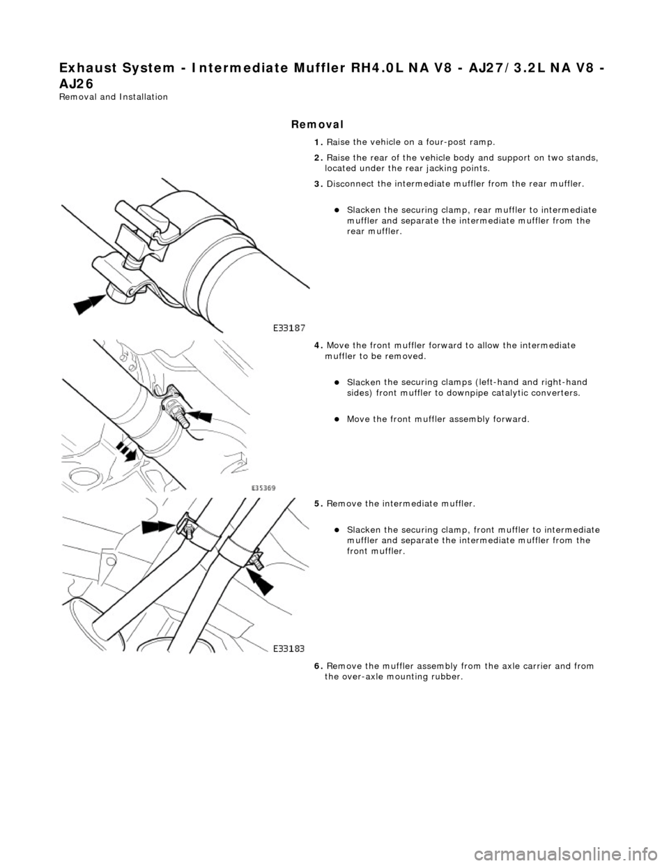
Exhaust System - Intermediate Muffler RH4.0L NA V8 - AJ27/3.2L NA V8 -
AJ26
Re mo
val and Installation
Remova
l
1.
Ra
ise the vehicle on a four-post ramp.
2. Raise the rear of the vehicle bo dy and support on two stands,
located under the re ar jacking points.
3. Disc
onnect the intermediate
muffler from the rear muffler.
Slacken the securi
ng clamp, re
ar muffler to intermediate
muffler and separate the in termediate muffler from the
rear muffler.
4. Move the front muf f
ler forwar
d to allow the intermediate
muffler to be removed.
Sl acke
n the securing clamps (left-hand and right-hand
sides) front muffler to downpipe catalytic converters.
Move the front muf f
ler
assembly forward.
5. Re
move the intermediate muffler.
Sl
acken the securi
ng clamp, front muffler to intermediate
muffler and separate the in termediate muffler from the
front muffler.
6. Remove the muffler assembly from the axle carrier and from
the over-axle mounting rubber.
Page 1679 of 2490

I
nstallation
7.
Clean and inspect al l e
xhaust joints.
1. Fi
t the intermediate muffler assembly.
F
it the muffler assembly to the axle carrier and to the
over-axle mounting rubber.
2. Locate the intermedi
ate muffl
er to the front muffler.
3. Cor
rectly position the front muffl
er in the catalytic converters
to align the correct reference / index indicator ring..
Tigh
ten the clamps (left-hand
and right-hand sides), front
muffler to catalytic converters.
4. Correctly position the intermedia te muffler at the front muffler
to align the correct reference / index indicator ring..
Tigh
ten the clamp, intermediate
mufflers to front muffler.
Page 1680 of 2490

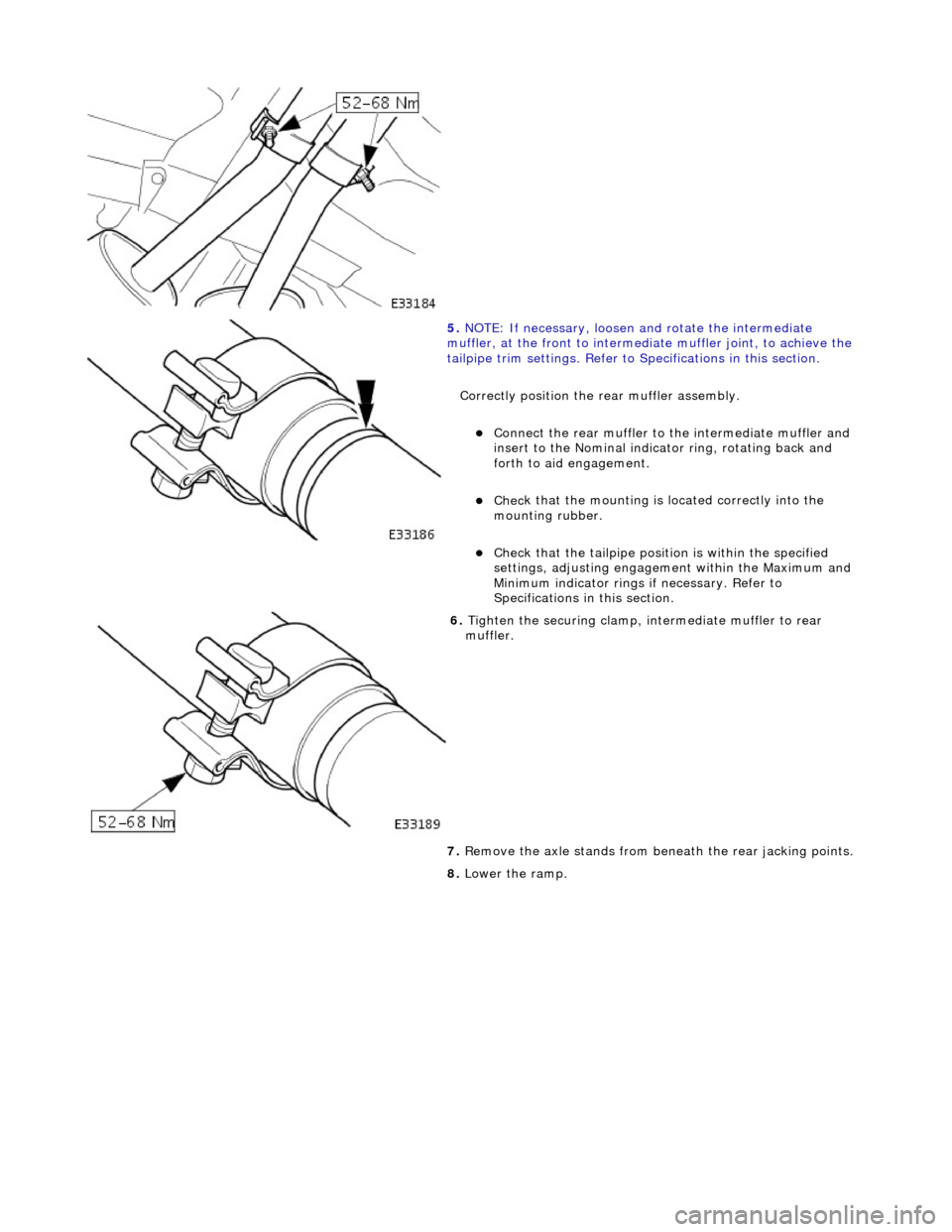
5.
NO TE
: If necessary, loosen and rotate the intermediate
muffler, at the front to intermediate muffler joint, to achieve the
tailpipe trim settings. Refer to Specifications in this section.
Correctly position the rear muffler assembly.
Connect the rear muffl
er to the intermediate muffler and
insert to the Nominal indicator ring, rotating back and
forth to aid engagement.
Chec k
that the mounting is located correctly into the
mounting rubber.
Chec k
that the tailpi
pe position is wi thin the specified
settings, adjusting engageme nt within the Maximum and
Minimum indicator rings if necessary. Refer to
Specifications in this section.
6. Tigh te
n the securing clamp, in
termediate muffler to rear
muffler.
7. Remove the axle stands from be neath the rear jacking points.
8. Lower the ramp.
Page 1681 of 2490

Exhaust System - Intermediate Muffler RH4
.0L SC V8 - AJ26
Re
moval and Installation
Remov
al
Installation
1. R
aise the vehicle on a four-post ramp.
2. Raise the rear of the vehicle bo dy and support on two stands,
located under the re ar jacking points.
3. Di
sconnect the intermediate
muffler from the rear muffler.
Sl
acken the securing clamp, re
ar muffler to intermediate
muffler and separate the in termediate muffler from the
rear muffler.
4. R
emove the intermediate muffler.
Sl
acken the securing clamp, front muffler to intermediate
muffler and separate the in termediate muffler from the
front muffler.
5. R
emove the muffler assembly
from the axle carrier and from
the over-axle mounting rubber.
6. Clean and inspect al l exhaust joints.
1. Fit the intermediate muffler assembly.
F
it the muffler assembly to the axle carrier and to the
over-axle mounting rubber.
Page 1682 of 2490

2. Locate the intermediate muffl er to the front muff
ler.
3. Cor r
ectly position the intermedia
te muffler at the front muffler
to align the correct refere nce / index indicator ring.
Tighte
n the clamp, intermediate
muffler to front muffler.
4. NO TE
: If necessary, loosen and rotate the intermediate
muffler, at the front to intermediate muffler joint, to achieve the
tailpipe trim settings. Refer to Specifications in this section.
Correctly position the rear muffler assembly.
Connect the rear muffl
er to the intermediate muffler and
insert to the Nominal indicator ring, rotating back and
forth to aid engagement.
Chec k
that the mounting is located correctly into the
mounting rubber.
Chec k
that the tailpi
pe position is wi thin the specified
settings, adjusting engageme nt within the Maximum and
Minimum indicator rings if necessary. Refer to
Specifications in this section.
5. Tighten the securing clamp, in termediate muffler to rear
muffler.
Page 1684 of 2490

Ex
haust System - Muff
ler and Tailpipe LH
Remo
val and Installation
Remov
a
l
Installation
1. Ra
ise the vehicle on a four-post ramp.
2. Slacken the securi
ng clamp, re
ar muffler to intermediate
muffler.
3. Re
move the rear muffler
and tailpipe assembly.
Separate the rear muffl er fr
om
the intermediate muffler.
Di
sengage the rear muffler mounting peg from the
mounting rubber.
R e
move the rear muffler asse
mbly. Rotate the assembly
back and forth to aid removal.
4. Clean the exhaust joints.
1. Fi
t the rear muffler and tailpipe assembly.
Connect
the rear muffl
er to the intermediate muffler and
insert to the Nominal indicator ring.
2. Position and align the rear mu ffler and tailpipe assembly.
Engage the peg with
the mounting rubber.
Chec
k
that the tailpi
pe position is wi thin the specified
settings, adjusting engageme nt within the Maximum and
Minimum indicator rings if necessary; refer to
Specifications in this section.
Page 1685 of 2490

3.
Tigh
ten the securing clamp, re
ar muffler to intermediate
muffler.
4. Lower the ramp.
Page 1686 of 2490

Ex
haust System - Muff
ler and Tailpipe RH
Remo
val and Installation
Remov
a
l
Installation
1. Ra
ise the vehicle on a four-post ramp.
2. Slacken the securi
ng clamp, re
ar muffler to intermediate
muffler.
3. Re
move the rear muffler
and tailpipe assembly.
Separate the rear muffl er fr
om
the intermediate muffler.
Di
sengage the rear muffler mounting peg from the
mounting rubber.
R e
move the rear muffler asse
mbly. Rotate the assembly
back and forth to aid removal.
4. Clean the exhaust joints.
1. Fi
t the rear muffler and tailpipe assembly.
Connect
the rear muffl
er to the intermediate muffler and
insert to the Nominal indicator ring.
2. Position and align the rear mu ffler and tailpipe assembly.
Engage the peg with
the mounting rubber.
Chec
k
that the tailpi
pe position is wi thin the specified
settings, adjusting engageme nt within the Maximum and
Minimum indicator rings if necessary; refer to
Specifications in this section.
Page 1687 of 2490

3.
Tigh
ten the securing clamp, re
ar muffler to intermediate
muffler.
4. Lower the ramp.
Page 1692 of 2490

Fuel Tank and Lines - Fuel Tank and Li
nes
Description an
d Operation
Fuel Tank
Parts List
The steel fuel tank is located inside the trunk and mounted across the vehicle behind the passenger compartment bulkhead.
The fuel tank is held in posi tion by two retaining straps fi tted to body-mounted brackets.
The fuel tank has an integral non-adjustable fill er pipe and integral breather and vapor pipework.
A single fuel pump is mounted inside the tank on vehicles with normally aspirated engines. For vehicles with supercharged
engines, two pumps are fitted in the tank. Fuel is drawn by the pump(s) from the fuel tank and supplied via the fuel lines
and 70 micron filter to the fuel rails.
The fuel lines run from front-to-rear down the vehicle's left-hand-side.
Ite
m
Part
Number
Descr
iption
1—Fu
el filler latch box
2—Pressure reli
ef pipe, ORVR
(shown) / tank breather pipe on non-ORVR systems
3—Tank grounding
cable
4—Evaporative flan
ge assembly
(ORVR type shown)
5—Trunk elec
trical harne
ss (part of)
6—Fue
l
level sensor
flange/connector
7—Fu
el tank retaining straps
8—F
u
el tank retaining stra
ps adjustable clamps
9—Fu
el tank retaining straps lower brackets
10—Tank vapor outlet pipe to un
derflo
or pipe quick-fit connector
11—F
u
el filler latch bo
x water drain pipe