battery JAGUAR X308 1998 2.G Repair Manual
[x] Cancel search | Manufacturer: JAGUAR, Model Year: 1998, Model line: X308, Model: JAGUAR X308 1998 2.GPages: 2490, PDF Size: 69.81 MB
Page 660 of 2490
Engine - Exhaust Camshaft LH
In-vehicle Repair
Removal
Installation
1. Open the engine compartment and fit paintwork protection
sheets.
2. Set the engine compartment cover to the service access
position.
3. Disconnect the batt ery ground cable.
пЃ¬Remove the battery cover.
4. Remove Exhaust Camshaft Sp rocket. Refer to Operation
12.65.74.
5. Remove the camshaft locking tool 303 - 530 (fitted for
previous operation).
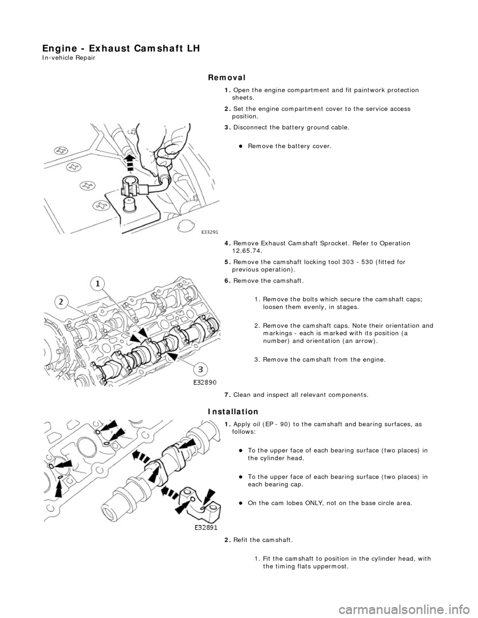
6. Remove the camshaft.
1. Remove the bolts which secure the camshaft caps; loosen them evenly, in stages.
2. Remove the camshaft caps. Note their orientation and
markings - each is marked with its position (a
number) and orientation (an arrow).
3. Remove the camshaft from the engine.
7. Clean and inspect all relevant components.
1. Apply oil (EP - 90) to the cams haft and bearing surfaces, as
follows:
пЃ¬To the upper face of each be aring surface (two places) in
the cylinder head.
пЃ¬To the upper face of each be aring surface (two places) in
each bearing cap.
пЃ¬On the cam lobes ONLY, not on the base circle area.
2. Refit the camshaft.
1. Fit the camshaft to position in the cylinder head, with the timing flats uppermost.
Page 661 of 2490

2. Fit the camshaft caps to their respective locations (5 to 9 from the front) and in the correct orientation
(arrow to front of engine).
3. Fit and tighten the cap securing bolts. Tighten evenly,
in stages, to 9 - 11 Nm.
3. Fit the camshaft locking tool 303 - 530 (fitted for following
operation) align the camshaft as necessary.
4. Refit Exhaust Camshaft Sprocket . Refer to Operation 12.65.74.
5. With the camshaft (303 - 530) and crankshaft (303 - 531)
setting tools removed, after the previous operation, adjust the
valve clearances on the exhaus t camshaft. refer to Operation
12.29.48.
6. Move the engine compartment co ver from the service position
and connect the gas struts.
7. Remove the paint protection sheets and close the cover.
8. Connect the battery and fit the battery cover.
пЃ¬Refer to the Battery Reconnection Procedure 86.15.15.
Page 662 of 2490
Engine - Exhaust Camshaft RH
In-vehicle Repair
Removal
Installation
1. Open the engine compartment and fit paintwork protection
sheets.
2. Set the engine compartment cover to the service access
position.
3. Disconnect the batt ery ground cable.
пЃ¬Remove the battery cover.
4. Remove Exhaust Camshaft Sp rocket. Refer to Operation
12.65.73.
5. Remove the camshaft locking tool 303 - 530 (fitted for
previous operation).
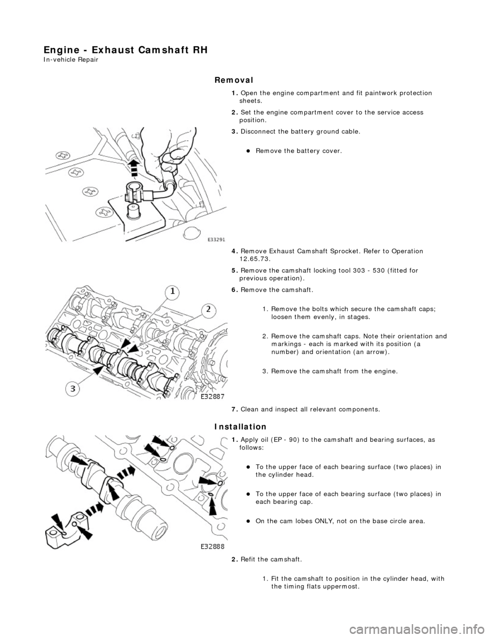
6. Remove the camshaft.
1. Remove the bolts which secure the camshaft caps; loosen them evenly, in stages.
2. Remove the camshaft caps. Note their orientation and
markings - each is marked with its position (a
number) and orientation (an arrow).
3. Remove the camshaft from the engine.
7. Clean and inspect all relevant components.
1. Apply oil (EP - 90) to the cams haft and bearing surfaces, as
follows:
пЃ¬To the upper face of each be aring surface (two places) in
the cylinder head.
пЃ¬To the upper face of each be aring surface (two places) in
each bearing cap.
пЃ¬On the cam lobes ONLY, not on the base circle area.
2. Refit the camshaft.
1. Fit the camshaft to position in the cylinder head, with the timing flats uppermost.
Page 663 of 2490

2. Fit the camshaft caps to their respective locations (5 to 9 from the front) and in the correct orientation
(arrow to front of engine).
3. Fit and tighten the cap securing bolts. Tighten evenly,
in stages, to 9 - 11 Nm.
3. Fit the camshaft locking tool 303 - 530 (fitted for following
operation) align the camshaft as necessary.
4. Refit Exhaust Camshaft Sprocket . Refer to Operation 12.65.73.
5. With the camshaft (303 - 530) and crankshaft (303 - 531)
setting tools removed, after the previous operation, adjust the
valve clearances on the exhaus t camshaft. refer to Operation
12.29.48.
6. Move the engine compartment co ver from the service position
and connect the gas struts.
7. Remove the paint protection sheets and close the cover.
8. Connect the battery and fit the battery cover.
пЃ¬Refer to the Battery Reconnection Procedure 86.15.15.
Page 664 of 2490
Engine - Exhaust Camshaft Sprocket LH4.0L NA V8 - AJ27
In-vehicle Repair
Removal
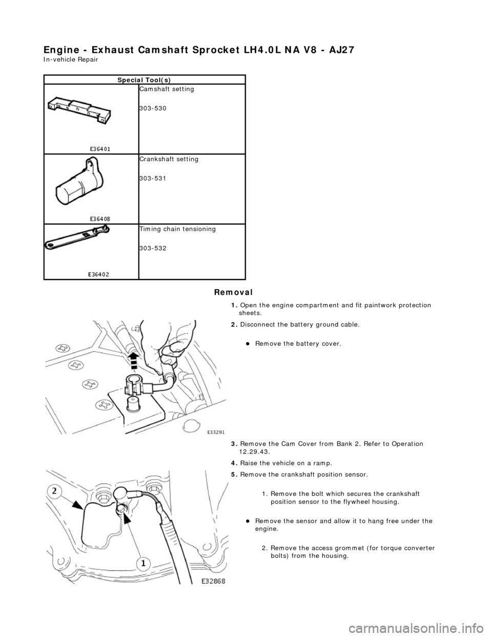
Special Tool(s)
Camshaft setting
303-530
Crankshaft setting
303-531
Timing chain tensioning
303-532
1. Open the engine compartment and fit paintwork protection
sheets.
2. Disconnect the batt ery ground cable.
пЃ¬Remove the battery cover.
3. Remove the Cam Cover from Ba nk 2. Refer to Operation
12.29.43.
4. Raise the vehicle on a ramp.
5. Remove the crankshaft position sensor.
1. Remove the bolt which secures the crankshaft position sensor to the flywheel housing.
пЃ¬Remove the sensor and allow it to hang free under the
engine.
2. Remove the access grommet (for torque converter bolts) from the housing.
Page 667 of 2490

4. Remove the tape and steel stri p from the timing cover upper
face. Wipe any residue of tape from the joint face.
5. Remove the camshaft locking tool.
6. Install the Cam Cover to Bank 2. Refer to Operation 12.29.43.
7. Raise the vehicle on the ramp.
8. Remove the crankshaft setting tool 303-531.
9. Install the crankshaft position sensor.
1. Install the sensor to the flywheel housing and fit the
securing bolt. Tighten to 8-12 Nm.
2. Install the access grommet to the housing.
10. Lower the ramp.
11. Remove the paint protection sheets and close the engine
compartment cover.
12. Connect the battery and in stall the battery cover.
пЃ¬Refer to the Battery Reconnection Procedure 86.15.15.
Page 668 of 2490
Engine - Exhaust Camshaft Sprocket LH4.0L SC V8 - AJ26/3.2L NA V8 -
AJ26
In-vehicle Repair
Removal
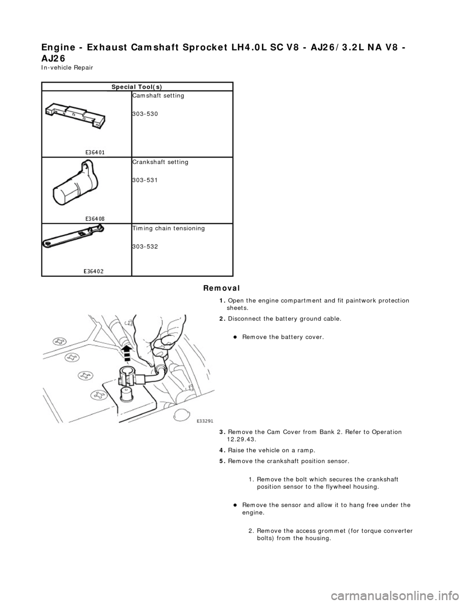
Special Tool(s)
Camshaft setting
303-530
Crankshaft setting
303-531
Timing chain tensioning
303-532
1. Open the engine compartment and fit paintwork protection
sheets.
2. Disconnect the batt ery ground cable.
пЃ¬Remove the battery cover.
3. Remove the Cam Cover from Ba nk 2. Refer to Operation
12.29.43.
4. Raise the vehicle on a ramp.
5. Remove the crankshaft position sensor.
1. Remove the bolt which secures the crankshaft position sensor to the flywheel housing.
пЃ¬Remove the sensor and allow it to hang free under the
engine.
2. Remove the access grommet (for torque converter bolts) from the housing.
Page 671 of 2490
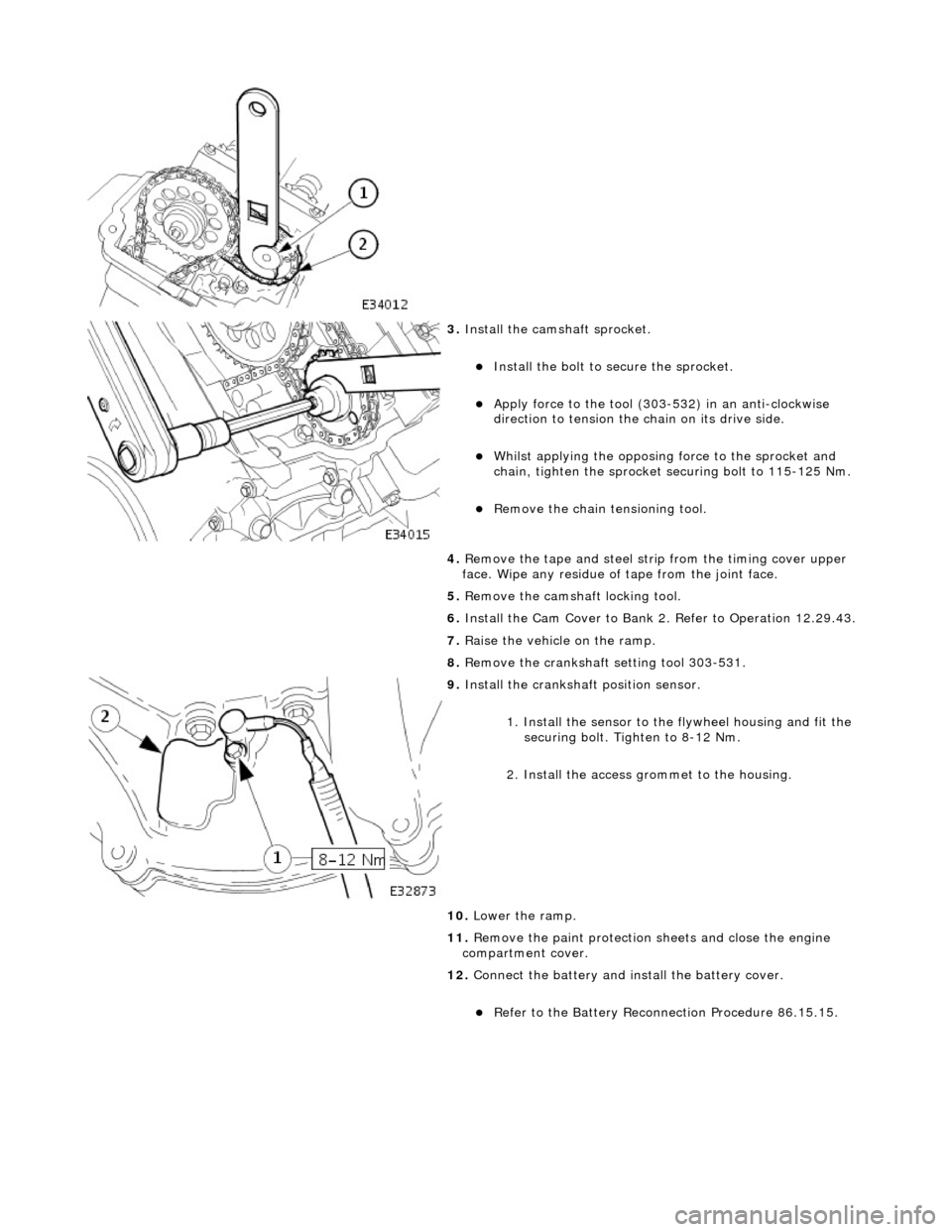
3. Install the cams haft sprocket.
пЃ¬Install the bolt to secure the sprocket.
пЃ¬Apply force to the tool (303-532) in an anti-clockwise
direction to tension the chain on its drive side.
пЃ¬Whilst applying the opposing force to the sprocket and
chain, tighten the sprocket securing bolt to 115-125 Nm.
пЃ¬Remove the chain tensioning tool.
4. Remove the tape and steel stri p from the timing cover upper
face. Wipe any residue of tape from the joint face.
5. Remove the camshaft locking tool.
6. Install the Cam Cover to Bank 2. Refer to Operation 12.29.43.
7. Raise the vehicle on the ramp.
8. Remove the crankshaft setting tool 303-531.
9. Install the crankshaft position sensor.
1. Install the sensor to the flywheel housing and fit the
securing bolt. Tighten to 8-12 Nm.
2. Install the access grommet to the housing.
10. Lower the ramp.
11. Remove the paint protection sheets and close the engine
compartment cover.
12. Connect the battery and in stall the battery cover.
пЃ¬Refer to the Battery Reconnection Procedure 86.15.15.
Page 672 of 2490
Engine - Exhaust Camshaft Sprocket RH4.0L NA V8 - AJ27
In-vehicle Repair
Removal
Special Tool(s)
Camshaft setting
303-530
Crankshaft setting
303-531
Timing chain tensioning
303-532
1. Open the engine compartment and fit paintwork protection
sheets.
2. Disconnect the batt ery ground cable.
пЃ¬Remove the battery cover.
3. Remove the Cam Cover from Ba nk 1. Refer to Operation
12.29.44.
4. Raise the vehicle on a ramp.
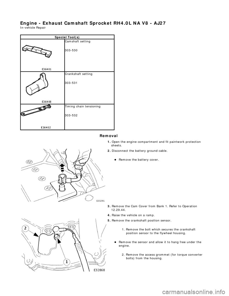
5. Remove the crankshaft position sensor.
1. Remove the bolt which secures the crankshaft position sensor to the flywheel housing.
пЃ¬Remove the sensor and allow it to hang free under the
engine.
2. Remove the access grommet (for torque converter bolts) from the housing.
Page 676 of 2490

11. Install the crankshaft position sensor.
1. Install the sensor to the flywheel housing and fit the
securing bolt. Tighten to 8-12 Nm.
2. Install the access grommet to the housing.
12. Lower the ramp.
13. Remove the paint protection sheets and close the engine
compartment cover.
14. Connect the battery and in stall the battery cover.
пЃ¬Refer to the Battery Reconnection Procedure 86.15.15.