battery JAGUAR X308 1998 2.G Repair Manual
[x] Cancel search | Manufacturer: JAGUAR, Model Year: 1998, Model line: X308, Model: JAGUAR X308 1998 2.GPages: 2490, PDF Size: 69.81 MB
Page 608 of 2490

Engine - Crankshaft Rear Seal4.0L SC V8 - AJ26
In-vehic
le Repair
Remov
a
l
S
p
ecial Tool(s)
Crankshaft Rear Oi
l Seal R
emover /
Replacer.
303 - 538
1. Open the engine compartment and fit paint protection sheets.
2. Disc
onnect the batt
ery ground cable.
пЃ¬Re
move the battery cover.
3. Remove the transmission. Refer to Operation 44.20. 01 in
Section 307-01B.
4. Remove the drive plat e. Refer to Operation (SC) 12.53.13.
5. Fi
t and align the seal removal tool 303 - 538 to the crankshaft.
1. Unscrew the two nuts towards the head of each bolt to allow the bolts to fit fully into the crankshaft.
2. Unscrew the center bolt until it is below the face of the main tool and position the tool to the rear of the
crankshaft.
3. Lightly tighten the two scre ws so that they fully locate
in the crankshaft.
6. Hold the tool against th e cr
an
kshaft and lightly and evenly
tighten the two nuts to the face of the tool; to secure the tool
and to hold it parallel to the face of the crankshaft.
7. Secure the oil seal to the tool using the three self-tapping
Page 610 of 2490
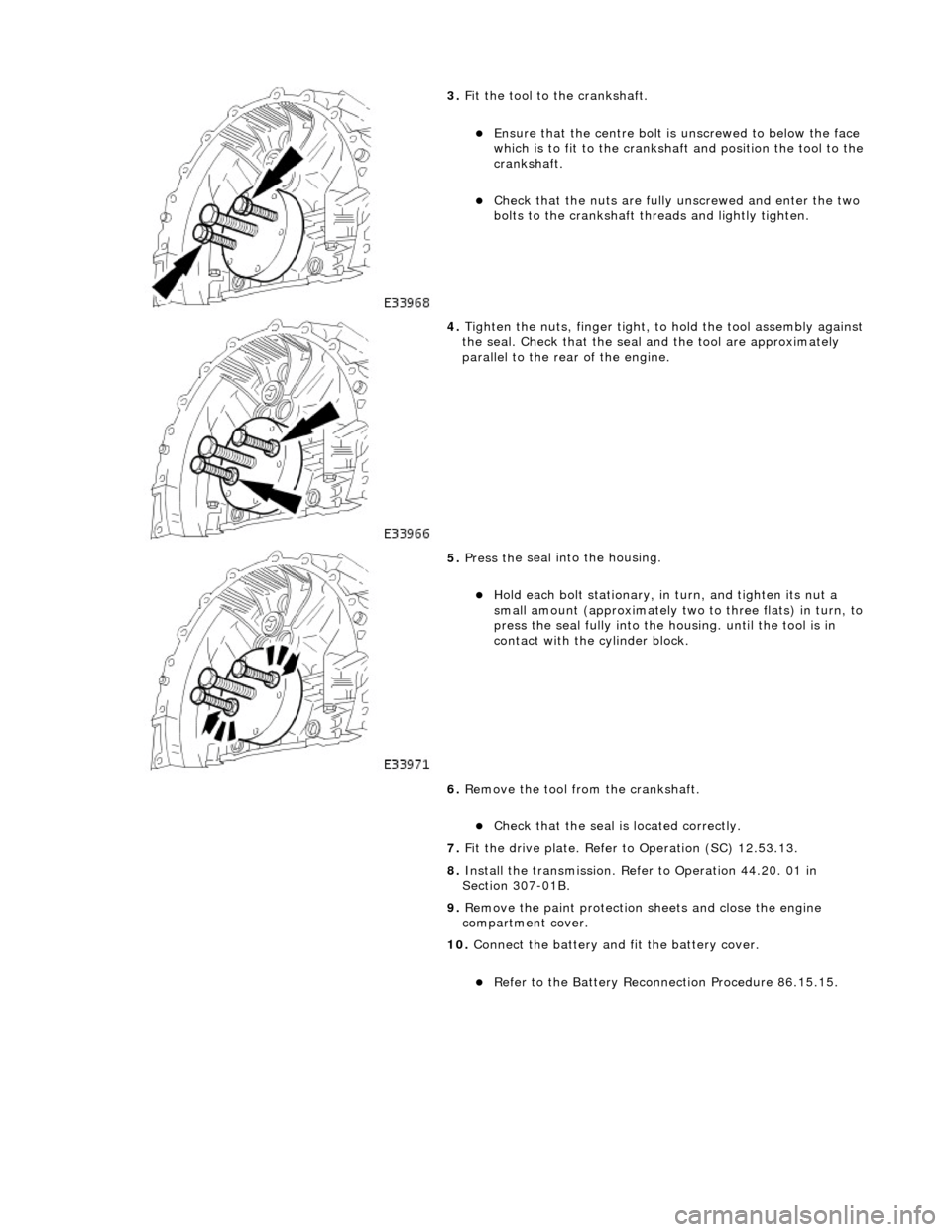
3.
Fit
the tool to the crankshaft.
пЃ¬En
sure that the cent
re bolt is unscrewe d to below the face
which is to fit to the crankshaft and position the tool to the
crankshaft.
пЃ¬Chec k that
the nuts are fully unscrewed and enter the two
bolts to the crankshaft thre ads and lightly tighten.
4. Tight
en the nuts, finger tight, to hold the tool assembly against
the seal. Check that the seal and the tool are approximately
parallel to the rear of the engine.
5. Pres s th
e seal into the housing.
пЃ¬Ho
ld e
ach bolt stationary, in
turn, and tighten its nut a
small amount (approximately two to three flats) in turn, to
press the seal fully into the housing. until the tool is in
contact with the cylinder block.
6. Remove the tool from the crankshaft.
пЃ¬Chec k that
the seal is located correctly.
7. Fit the drive plate. Refer to Operation (SC) 12.53.13.
8. Install the transmission. Refer to Operation 44.20. 01 in
Section 307-01B.
9. Remove the paint protection sheets and close the engine
compartment cover.
10. Connect the battery and fit the battery cover.
пЃ¬Re
fe
r to the Battery Reconnection Procedure 86.15.15.
Page 611 of 2490
E
ngine - Cylinder Head LH
In-ve
hicle Repair
Remova
l
CAU
TION: If a replacement cylinder head is to be installed to a
vehicle with variable camshaft timing (VCT) the cylinder head m ust have the
oil gallery blind rivet removed before installation.
Spe
cial Tool(s)
Cams
haft setting
303-530
Ti
ming chain tensioning
303-532
Wedges, prim
ary chain
303-533
Cr
ankshaft setting
303-531
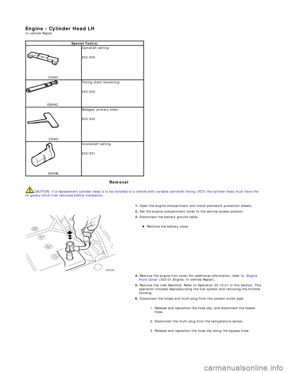
1.
Open the engine compartment and install paintwork protection sheets.
2. Set the engine compartment cover to the service access position.
3.
Disconnect the battery ground cable.
пЃ¬Re
move the battery cover.
4. Remove the engine fron cover.For additional information, refer to: Engine
Front Cover (303-01 Engi
ne, In-vehicle Repair).
5. Remove the Inlet Manifold. Refer to Operation 30.15.01 in this Section. This operation includes depressurising the fuel system and removing the throttle
housing.
6. Disconnect the hoses and multi-plug from the coolant outlet pipe.
1. Release and reposition the hose clip, and disconnect the heater hose.
2. Disconnect the multi-plug from the temperature sensor.
3. Release and reposition the hose clip along the bypass hose.
Page 626 of 2490

46
. Mov
e the engine compartment cover from the service position and connect
the gas struts.
47. Remove the paint protection sheets and close the cover.
48. Connect the battery and install the battery cover.
пЃ¬Refe
r to the Battery Reconne
ction Procedure 86.15.15.
Page 627 of 2490
E
ngine - Cylinder Head RH
In-ve
hicle Repair
Remova
l
CAU
TION: If a replacement cylinder head is to be installed to a
vehicle with variable camshaft timing (VCT) the cylinder head m ust have the
oil gallery blind rivet removed before installation.
Spe
cial Tool(s)
Cams
haft setting
303-530
Ti
ming chain tensioning
303-532
Wedges, prim
ary chain
303-533
Cr
ankshaft setting
303-531
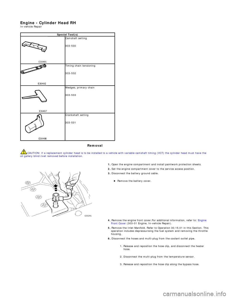
1.
Open the engine compartment and install paintwork protection sheets.
2. Set the engine compartment cover to the service access position.
3.
Disconnect the battery ground cable.
пЃ¬Re
move the battery cover.
4. Remove the engine front cover.For additional information, refer to: Engine
Front Cover (303-01 Engi
ne, In-vehicle Repair).
5. Remove the Inlet Manifold. Refer to Operation 30.15.01 in this Section. This operation includes depressurising the fuel system and removing the throttle
housing.
6. Disconnect the hoses and multi-plug from the coolant outlet pipe.
1. Release and reposition the hose clip, and disconnect the heater hose.
2. Disconnect the multi-plug from the temperature sensor.
3. Release and reposition the hose clip along the bypass hose.
Page 641 of 2490
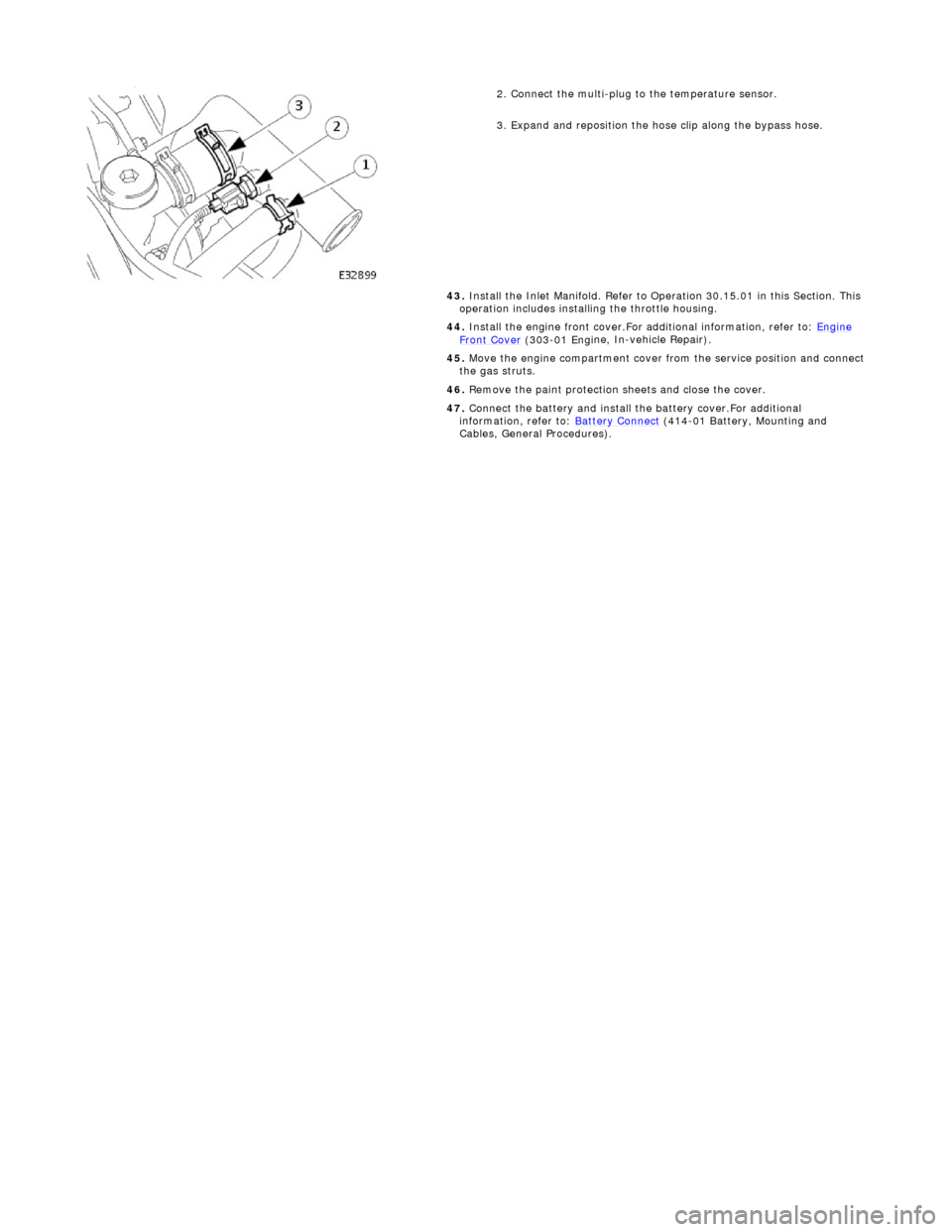
2.
Connect the multi-plug to the temperature sensor.
3. Expand and reposition the hose clip along the bypass hose.
43. Install the Inlet Manifold. Refer to Operation 30.15.01 in this Section. This
operation includes installing the throttle housing.
44. Install the engine front cover.For additional information, refer to: Engine
Front Cover (303-01 Engi
ne, In-vehicle Repair).
45. Move the engine compartment cover from the service position and connect
the gas struts.
46. Remove the paint protection sheets and close the cover.
47. Connect the battery and install th e battery cover.For additional
information, refer to: Battery Connect
(414
-01 Battery, Mounting and
Cables, General Procedures).
Page 642 of 2490
Engine - Engine Front Cover
In-vehic
le Repair
Remov
a
l
1.
Op
en the engine compartment and fit paintwork protection
sheets.
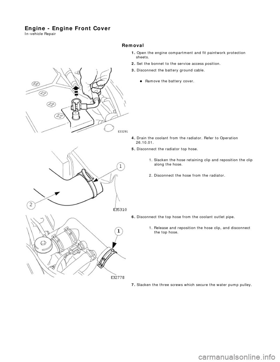
2. Set the bonnet to the service access position.
3. Disc
onnect the batt
ery ground cable.
пЃ¬Re
move the battery cover.
4. Drain the coolant from the radiator. Refer to Operation
26.10.01.
5. Disc onne
ct the radiator top hose.
1. Slacken the hose retaining clip and reposition the clip
along the hose.
2. Disconnect the hose from the radiator.
6. Disc
onnect the top hose from the coolant outlet pipe.
1. Release and reposition th e hose clip, and disconnect
the top hose.
7. Slacken the three screws which secure the water pump pulley.
Page 650 of 2490
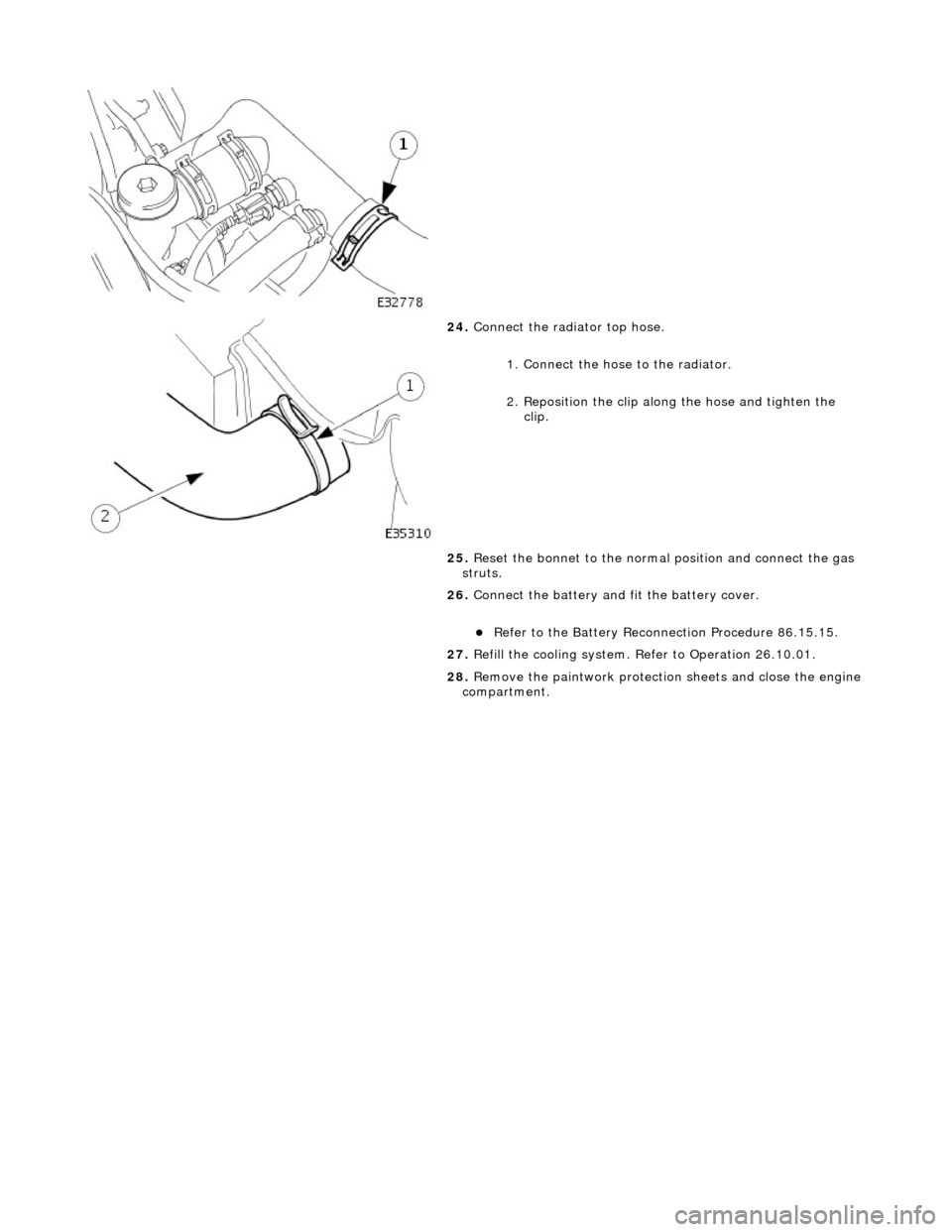
24.
Connect
the radiator top hose.
1. Connect the hose to the radiator.
2. Reposition the clip along the hose and tighten the clip.
25. Reset the bonnet to the normal position and connect the gas
struts.
26. Connect the battery and fit the battery cover.
пЃ¬Refe
r to the Battery Reconnection Procedure 86.15.15.
27. Refill the cooling system. Refer to Operation 26.10.01.
28. Remove the paintwork protection sheets and close the engine
compartment.
Page 651 of 2490
Engine - Engine Fron
t Cover Gasket
In-v
ehicle Repair
Remov
al
1.
O
pen the engine compartment and fit paintwork protection
sheets.
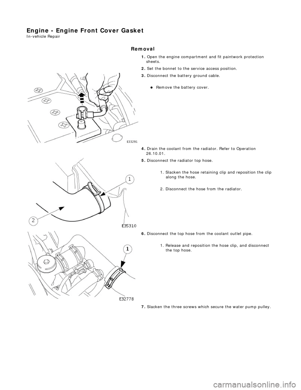
2. Set the bonnet to the service access position.
3. Di
sconnect the batt
ery ground cable.
пЃ¬R
emove the battery cover.
4. Drain the coolant from the radiator. Refer to Operation
26.10.01.
5. Disc
onnect the radiator top hose.
1. Slacken the hose retaining clip and reposition the clip
along the hose.
2. Disconnect the hose from the radiator.
6. Di
sconnect the top hose from the coolant outlet pipe.
1. Release and reposition th e hose clip, and disconnect
the top hose.
7. Slacken the three screws which secure the water pump pulley.
Page 659 of 2490
21
.
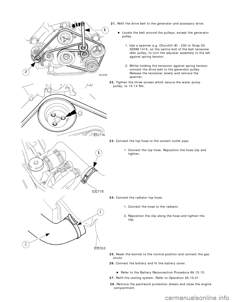
Refit the drive belt to the generator and accessory drive.
пЃ¬Locat
e the belt around the pulleys, except the generator
pulley.
1. Use a spanner e.g. Churchill JD - 230 or Snap On XDHM 1415, on the centre bo lt of the belt tensioner
idler pulley, to turn the adju ster assembly to the left
against spring tension.
2. Whilst holding the tensioner against spring tension, connect the drive belt to the generator pulley.
Release the tensioner sl owly and remove the
spanner.
22
.
Tighten the three screws wh ich secure the water pump
pulley, to 10-14 Nm.
23
.
Connect the top hose to the coolant outlet pipe.
1. Connect the top hose. Reposition the hose clip and tighten.
24
.
Connect the radiator top hose.
1. Connect the hose to the radiator.
2. Reposition the clip along the hose and tighten the clip.
25. Reset the bonnet to the normal position and connect the gas
struts.
26. Connect the battery and fit the battery cover.
пЃ¬Re
fer to the Battery Reconnection Procedure 86.15.15.
27. Refill the cooling system. Refer to Operation 26.10.01.
28
.
Remove the paintwork protection sheets and close the engine
compartment.