check oil JAGUAR X308 1998 2.G Owner's Manual
[x] Cancel search | Manufacturer: JAGUAR, Model Year: 1998, Model line: X308, Model: JAGUAR X308 1998 2.GPages: 2490, PDF Size: 69.81 MB
Page 646 of 2490
In
stallation
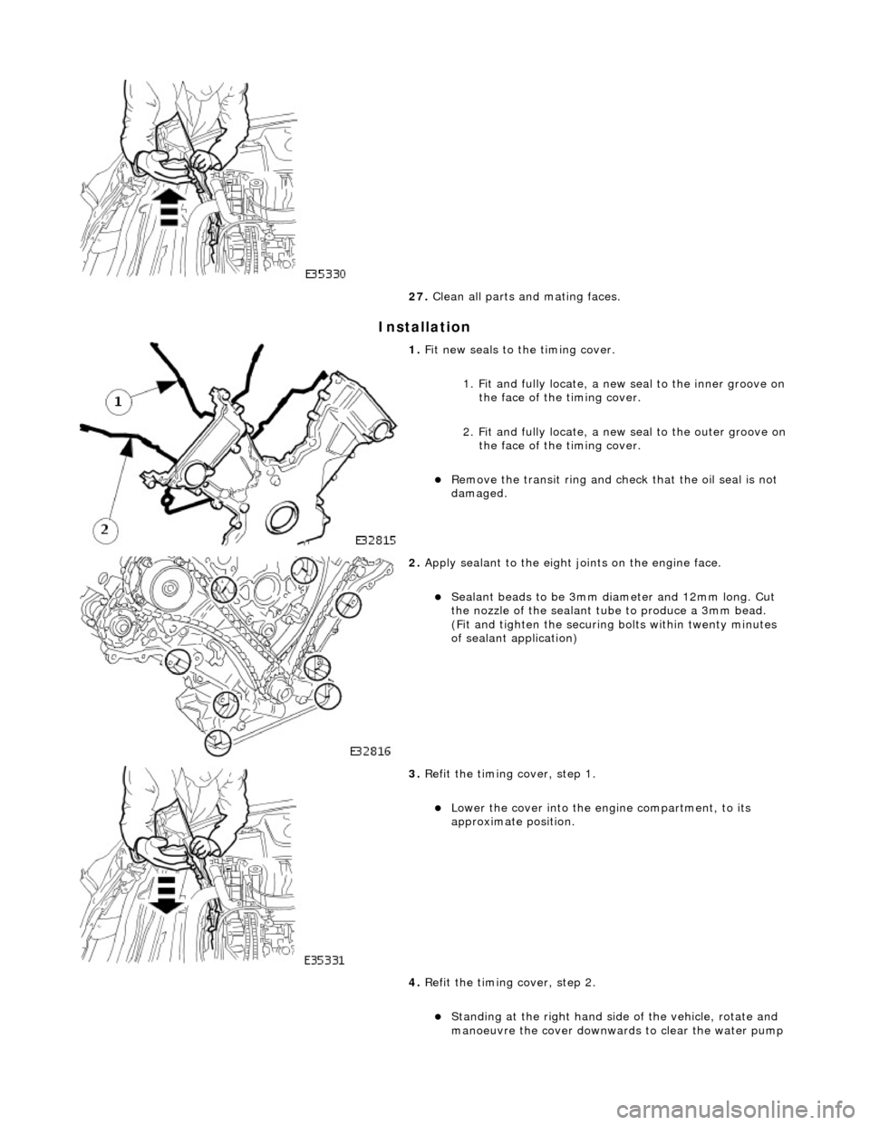
27
. Clean all parts and mating faces.
1. Fit ne
w seals to the timing cover.
1. Fit and fully locate, a new seal to the inner groove on the face of the timing cover.
2. Fit and fully locate, a new seal to the outer groove on the face of the timing cover.
пЃ¬Re
move the transit ring and check that the oil seal is not
damaged.
2. Appl y s
ealant to the eight joints on the engine face.
пЃ¬Sealant
beads to be 3mm di ameter an
d 12mm long. Cut
the nozzle of the sealant tube to produce a 3mm bead.
(Fit and tighten the securing bolts within twenty minutes
of sealant application)
3. Re
fit the timing cover, step 1.
пЃ¬Lo
wer th
e cover into the engine compartment, to its
approximate position.
4. Refit the timing cover, step 2.
пЃ¬Stan din
g at the right hand side
of the vehicle, rotate and
manoeuvre the cover downwards to clear the water pump
Page 751 of 2490
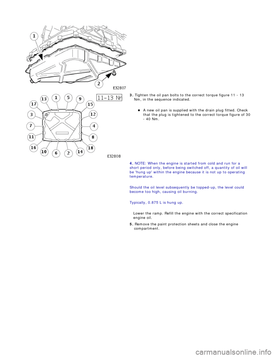
3. Tighten the oil pan bolts to the correct torque figure 11 - 13
Nm, in the sequence indicated.
пЃ¬A new oil pan is supplied with the drain plug fitted. Check
that the plug is tightened to the correct torque figure of 30 - 40 Nm.
4. NOTE: When the engine is star ted from cold and run for a
short period only, before being swit ched off, a quantity of oil will
be 'hung up' within the engine because it is not up to operating
temperature.
Should the oil level subsequently be topped-up, the level could
become too high, causing oil burning.
Typically, 0.875 L is hung up.
Lower the ramp. Refill the engine with the correct specification
engine oil.
5. Remove the paint protection sheets and close the engine
compartment.
Page 768 of 2490
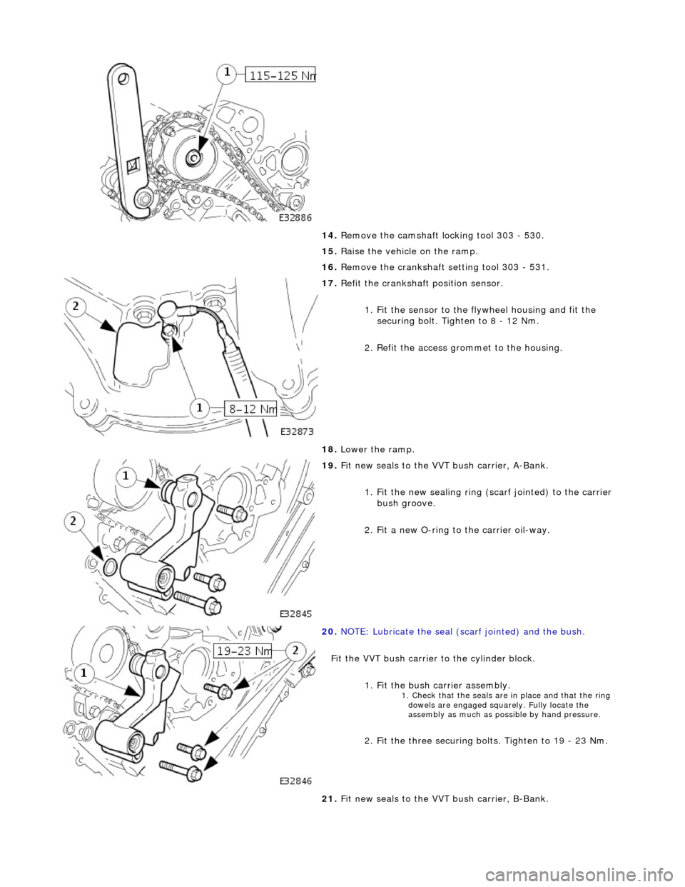
14. Remove the camshaft locking tool 303 - 530.
15. Raise the vehicle on the ramp.
16. Remove the crankshaft setting tool 303 - 531.
17. Refit the crankshaft position sensor.
1. Fit the sensor to the fl ywheel housing and fit the
securing bolt. Tighten to 8 - 12 Nm.
2. Refit the access grommet to the housing.
18. Lower the ramp.
19. Fit new seals to the VVT bush carrier, A-Bank.
1. Fit the new sealing ring ( scarf jointed) to the carrier
bush groove.
2. Fit a new O-ring to the carrier oil-way.
20. NOTE: Lubricate the seal (s carf jointed) and the bush.
Fit the VVT bush carrier to the cylinder block.
1. Fit the bush carrier assembly.
1. Check that the seals are in place and that the ring dowels are engaged squa rely. Fully locate the
assembly as much as possible by hand pressure.
2. Fit the three securing bolts. Tighten to 19 - 23 Nm.
21. Fit new seals to the VVT bush carrier, B-Bank.
Page 769 of 2490

1. Fit the new sealing ring (scarf jointed) to the carrier bush groove.
2. Fit a new O-ring to the carrier oil-way.
22. NOTE: Lubricate the seal (s carf jointed) and the bush.
Fit the VVT bush carrier to the cylinder block.
1. Fit the bush carrier assembly.
1. Check that the seals are in place and that the ring dowels are engaged squa rely. Fully locate the
assembly as much as possible by hand pressure.
2. Fit the two securing bolts and one nut. Tighten to 19 - 23 Nm.
23. Refit the Timing Cover. Refer to Operation 12.65.01 in this
Section.
24. Move the engine compartment cover from the service position
and connect the gas struts.
25. Remove the paint protection sheets and close the cover.
26. Connect the battery and fit the battery cover.
пЃ¬Refer to the Battery Reconnection Procedure 86.15.15.
Page 784 of 2490

and chain, tighten the sprocket securing bolt to 115 -
125 Nm.
7. Tighten the VVT unit securing bolt.
1. Whilst still applying the opposing force to the
sprocket and chain (using 303 - 532), check that the
wedges are still in place, tighten the VVT unit
securing bolt to 115 - 125 Nm.
пЃ¬Remove the chain tensioning tool and the wedge(s).
8. Remove the camshaft locking tool 303 - 530.
9. Raise the vehicle on the ramp.
10. Remove the crankshaft setting tool 303 - 531.
11. Refit the crankshaft position sensor.
1. Fit the sensor to the fl ywheel housing and fit the
securing bolt. Tighten to 8-12 Nm.
2. Refit the access grommet to the housing.
12. Lower the ramp.
13. Fit new seals to the VVT bush carrier.
1. Fit the new sealing ring (scarf jointed) to the carrier bush groove.
2. Fit a new O-ring to the carrier oil-way.
14. Fit the VVT bush carrier to the cylinder block.
Page 838 of 2490
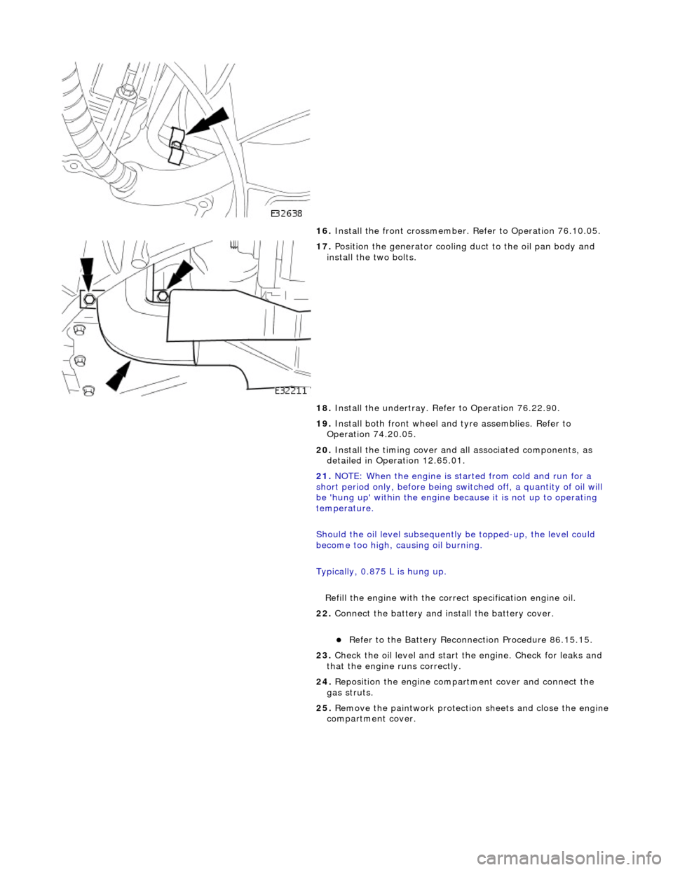
16. Install the front cr ossmember. Refer to Operation 76.10.05.
17. Position the generator cooling duct to the oil pan body and
install the two bolts.
18. Install the undert ray. Refer to Operation 76.22.90.
19. Install both front wheel and tyre assemblies. Refer to
Operation 74.20.05.
20. Install the timing cover and al l associated components, as
detailed in Operation 12.65.01.
21. NOTE: When the engine is star ted from cold and run for a
short period only, before being swit ched off, a quantity of oil will
be 'hung up' within the engine because it is not up to operating
temperature.
Should the oil level subsequently be topped-up, the level could
become too high, causing oil burning.
Typically, 0.875 L is hung up.
Refill the engine with the correct specification engine oil.
22. Connect the battery and in stall the battery cover.
пЃ¬Refer to the Battery Reconnection Procedure 86.15.15.
23. Check the oil level and start th e engine. Check for leaks and
that the engine runs correctly.
24. Reposition the engine compartment cover and connect the
gas struts.
25. Remove the paintwork protection sheets and close the engine
compartment cover.
Page 847 of 2490
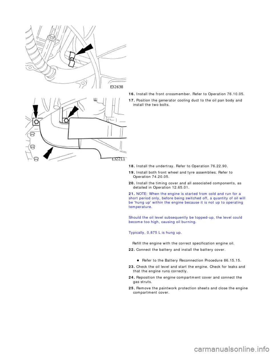
16. Install the front cr ossmember. Refer to Operation 76.10.05.
17. Position the generator cooling duct to the oil pan body and
install the two bolts.
18. Install the undert ray. Refer to Operation 76.22.90.
19. Install both front wheel and tyre assemblies. Refer to
Operation 74.20.05.
20. Install the timing cover and al l associated components, as
detailed in Operation 12.65.01.
21. NOTE: When the engine is star ted from cold and run for a
short period only, before being swit ched off, a quantity of oil will
be 'hung up' within the engine because it is not up to operating
temperature.
Should the oil level subsequently be topped-up, the level could
become too high, causing oil burning.
Typically, 0.875 L is hung up.
Refill the engine with the correct specification engine oil.
22. Connect the battery and in stall the battery cover.
пЃ¬Refer to the Battery Reconnection Procedure 86.15.15.
23. Check the oil level and start th e engine. Check for leaks and
that the engine runs correctly.
24. Reposition the engine compartment cover and connect the
gas struts.
25. Remove the paintwork protection sheets and close the engine
compartment cover.
Page 858 of 2490
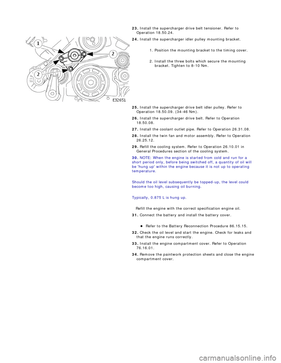
23.
Install the supercharger driv e belt tensioner. Refer to
Operation 18.50.24.
24. Install the supercharger idle r pulley mounting bracket.
1. Position the mounting bracket to the timing cover.
2. Install the three bolts which secure the mounting bracket. Tighten to 8-10 Nm.
25. Install the supercharger drive belt idler pulley. Refer to
Operation 18.50.09. (34-46 Nm).
26. Install the supercharger driv e belt. Refer to Operation
18.50.08.
27. Install the coolant outlet pipe. Refer to Operation 26.31.08.
28. Install the twin fan and motor assembly. Refer to Operation
26.25.12.
29. Refill the cooling system. Refer to Operation 26.10.01 in
General Procedures section of the cooling system.
30. NOTE: When the engine is star ted from cold and run for a
short period only, before being swit ched off, a quantity of oil will
be 'hung up' within the engine because it is not up to operating
temperature.
Should the oil level subsequently be topped-up, the level could
become too high, causing oil burning.
Typically, 0.875 L is hung up.
Refill the engine with the correct specification engine oil.
31. Connect the battery and in stall the battery cover.
пЃ¬Refer to the Battery Reconnection Procedure 86.15.15.
32. Check the oil level and start th e engine. Check for leaks and
that the engine runs correctly.
33. Install the engine compartmen t cover. Refer to Operation
76.16.01.
34. Remove the paintwork protection sheets and close the engine
compartment cover.
Page 918 of 2490
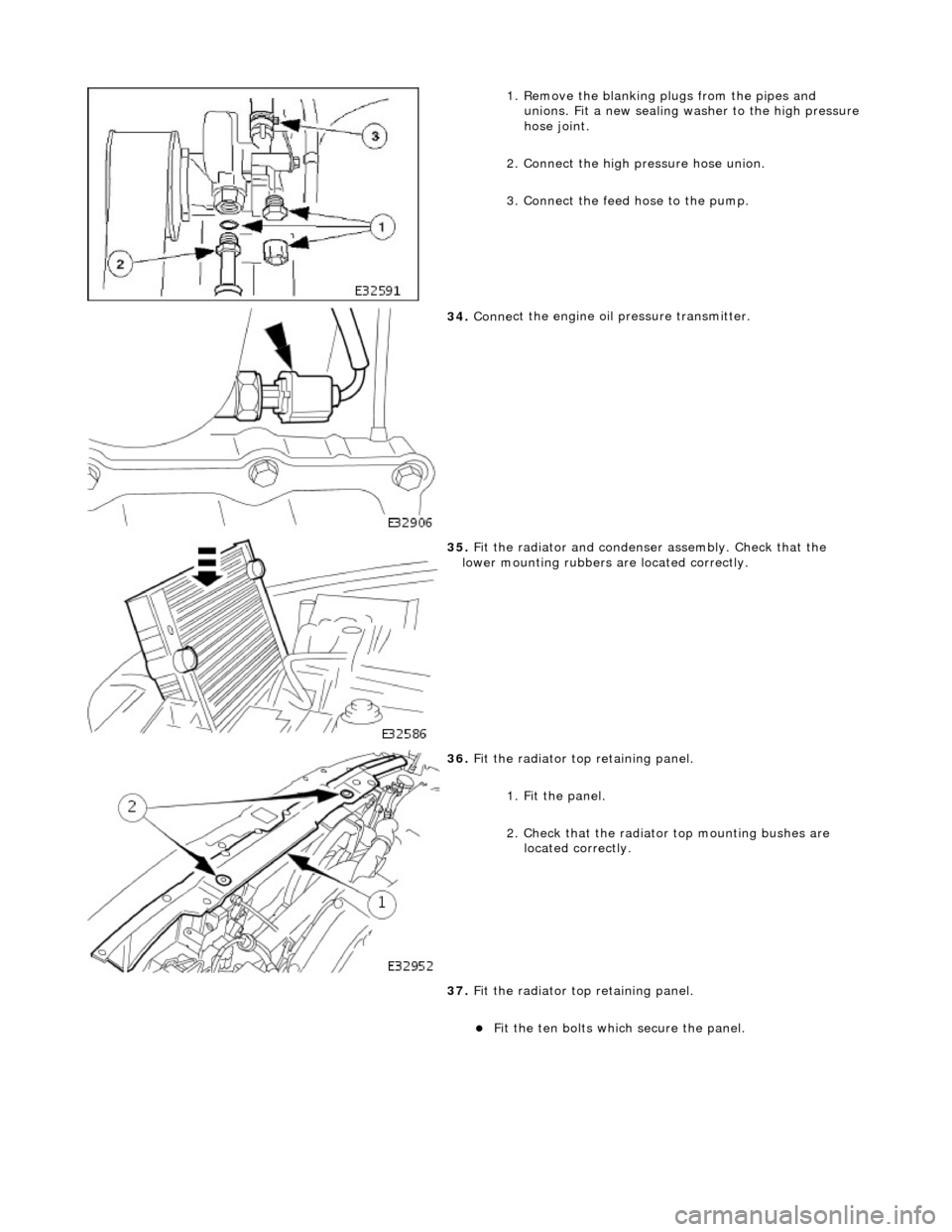
1.
Remove the blanking plugs from the pipes and
unions. Fit a new sealing washer to the high pressure
hose joint.
2. Connect the high pressure hose union.
3. Connect the feed hose to the pump.
34 . Conne
ct the engine oil
pressure transmitter.
35 .
Fit the radiator and
condense
r assembly. Check that the
lower mounting rubbers are located correctly.
36 . Fit the radiator top
retaining panel.
1. Fit the panel.
2. Check that the radiator top mounting bushes are
located correctly.
37. Fit the radiator top retaining panel.
пЃ¬Fit
the ten bolts which secure the panel.
Page 935 of 2490
Pinpoint test
A: P0116, P0125
Connector
loose or corroded
*
D
TC P0118 ECT circuit high input
Sensor short
Harness open circui
t
Harness short
Connector loose or corroded
*
*
*
*
GO to Pinpoint
Test C
*
D
TC P1474 Intercooler coolant pump relay malfunction
Intercooler pump relay
failure
Intercooler pump relay to ECM drive circuit
fault Intercooler pump relay coil ground circuit
fault Harness fault
Connector loose or corroded
Connector pins(s) bent or tracking between
connections ECM power supply fault
*
*
*
*
*
*
*
GO to Pinpoint
Test D
*
P
INPOINT TEST A : P0116, P0125
T
EST CONDITIONS
D
ETAILS/RESULTS/ACTIONS
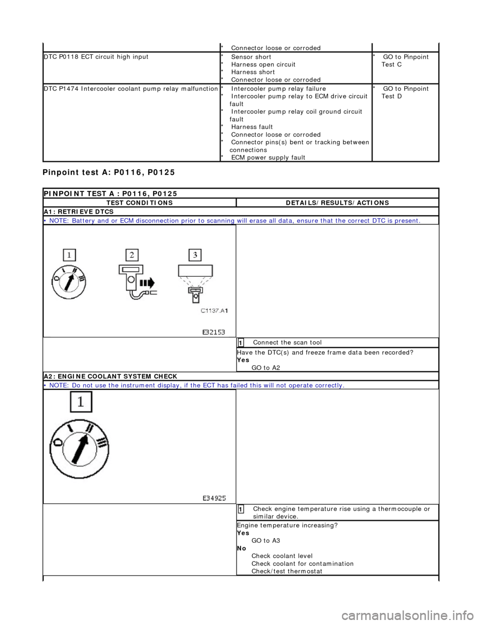
A1
: RETRIEVE DTCS
•
NOTE: Battery and or ECM disconnection prior to scanning wi
ll erase all data, ensure that the correct DTC is present.
Conne
ct the scan tool
1
Have the DTC(s) and fr
eeze
frame data been recorded?
Yes GO to A2
A2: ENGINE
COOLANT SYSTEM CHECK
•
NOTE: Do not use the instrument display, if th
e ECT has failed this will not operate correctly.
Chec
k engine temperature rise using a thermocouple or
similar device.
1
Engine
temperature increasing?
Yes GO to A3
No Check coolant level
Check coolant for contamination
Check/test thermostat