engine coolant JAGUAR X308 1998 2.G Repair Manual
[x] Cancel search | Manufacturer: JAGUAR, Model Year: 1998, Model line: X308, Model: JAGUAR X308 1998 2.GPages: 2490, PDF Size: 69.81 MB
Page 994 of 2490

Engine Cooling - Thermostat4.0L SC V8 - AJ26
Remo
val and Installation
Remov
a
l
Installation
1.
Op
en the engine compartment and fit paintwork protection
sheets.
2. Drain the radiator. Refer to Ge neral Procedures. Retain the
coolant drain tray in position to catch any spillage when
removing the outlet pipe.
3. Disc
onnect the bottom hose
from the coolant outlet pipe.
1. Release and reposi tion the hose clip.
2. Disconnect the bottom hose.
4. Re
move the thermostat from the outlet pipe.
1. Remove the three bolts which secure the thermostat cover to the outlet pipe.
2. Remove the thermostat cover, the thermostat and
the seal from the outlet pipe. Discard the seal.
1. Installation is th e reverse of the re moval procedure.
Use new seali
ng rings on th
e coolant outlet pipe and
thermostat housing.
The t he
rmostat ball valve must
locate in the recess in the
cover.
2. Tighten the thermostat cover bolts to 8-10 Nm.
3. Refill the cooling system as de scribed in General Procedures.
Page 995 of 2490

Engine Co
oling - Thermostat Housing
Cover4.0L NA V8 - AJ27/3.2L NA V8
- AJ26
Re
moval and Installation
Remov
al
Installation
1. O
pen the engine compartment and fit paintwork protection
sheets.
2. Drain the radiator. Refer to Ge neral Procedures. Retain the
coolant drain tray in position to catch any spillage when
removing the thermostat cover.
3. Remove the engine cove r panels for access.
4. Di
sconnect the radiator bott
om hose from the thermostat
cover.
1. Release and reposition th e hose clip, and disconnect
the bottom hose from th e thermostat cover.
5. R
emove the thermostat cover.
1. Remove the three bolts which secure the thermostat cover to the housing.
2. Remove the thermostat cover from the housing.
6. R
emove the thermostat from the housing.
1. Remove the thermostat from the housing.
2. Remove (and discard) th e seal from the thermostat.
Fit a new seal to the
thermost
at. The seal may be fitted
either way round.
1. Installation is th e reverse of the re moval procedure.
2. Fit the thermostat so that the vent ball valve locates in the
recess in the cover.
3. Tighten the thermostat cover bolts to 8-10 Nm.
Page 997 of 2490

Engine Cooling - Thermostat Housing Cover4.
0L SC V8 - AJ26
Re
moval and Installation
Remov
al
Installation
1.
O
pen the engine compartment and fit paintwork protection
sheets.
2. Drain the radiator. Refer to Ge neral Procedures. Retain the
coolant drain tray in position to catch any spillage when
removing the outlet pipe.
3. Di
sconnect the bottom hose
from the coolant outlet pipe.
1. Release and reposi tion the hose clip.
2. Disconnect the bottom hose.
4. R
emove the thermostat from the outlet pipe.
1. Remove the three bolts which secure the thermostat cover to the outlet pipe.
2. Remove the thermostat cover, the thermostat and
the seal from the outlet pipe. Discard the seal.
1. Installation is th e reverse of the re moval procedure.
Use new
sealing rings on th
e coolant outlet pipe and
thermostat housing.
The t
hermostat ball valve must
locate in the recess in the
cover.
2. Tighten the thermostat cover bolts to 8-10 Nm.
3. Refill the cooling system as de scribed in General Procedures.
Page 998 of 2490

Engine Cooli
ng - Thermostat Housing
Cover Seal4.0L NA V8 - AJ27/3.2L
NA V8 - AJ26
Re mo
val and Installation
Remova
l
Installation
1. Op
en the engine compartment and fit paintwork protection
sheets.
2. Drain the radiator. Refer to Ge neral Procedures. Retain the
coolant drain tray in position to catch any spillage when
removing the thermostat cover.
3. Remove the engine cove r panels for access.
4. Disc
onnect the radiator bott
om hose from the thermostat
cover.
1. Release and reposition th e hose clip, and disconnect
the bottom hose from th e thermostat cover.
5. Re
move the thermostat cover.
1. Remove the three bolts which secure the thermostat cover to the housing.
2. Remove the thermostat cover from the housing.
6. Re
move the thermostat from the housing.
1. Remove the thermostat from the housing.
2. Remove (and discard) th e seal from the thermostat.
Fit a new seal to the
thermostat. Th
e seal may be fitted
either way round.
1. Installation is th e reverse of the re moval procedure.
2. Fit the thermostat so that the vent ball valve locates in the
recess in the cover.
3. Tighten the thermostat cover bolts to 8-10 Nm.
Page 1000 of 2490

Engine Cooli
ng - Thermostat Housin
g Cover Seal4.0L SC V8 - AJ26
Remo
val and Installation
Remov
a
l
Installation
1.
Op
en the engine compartment and fit paintwork protection
sheets.
2. Drain the radiator. Refer to Ge neral Procedures. Retain the
coolant drain tray in position to catch any spillage when
removing the outlet pipe.
3. Disc
onnect the bottom hose
from the coolant outlet pipe.
1. Release and reposi tion the hose clip.
2. Disconnect the bottom hose.
4. Re
move the thermostat from the outlet pipe.
1. Remove the three bolts which secure the thermostat cover to the outlet pipe.
2. Remove the thermostat cover, the thermostat and
the seal from the outlet pipe. Discard the seal.
1. Installation is th e reverse of the re moval procedure.
Use new seali
ng rings on th
e coolant outlet pipe and
thermostat housing.
The t he
rmostat ball valve must
locate in the recess in the
cover.
2. Tighten the thermostat cover bolts to 8-10 Nm.
3. Refill the cooling system as de scribed in General Procedures.
Page 1002 of 2490

In
stallation
2.
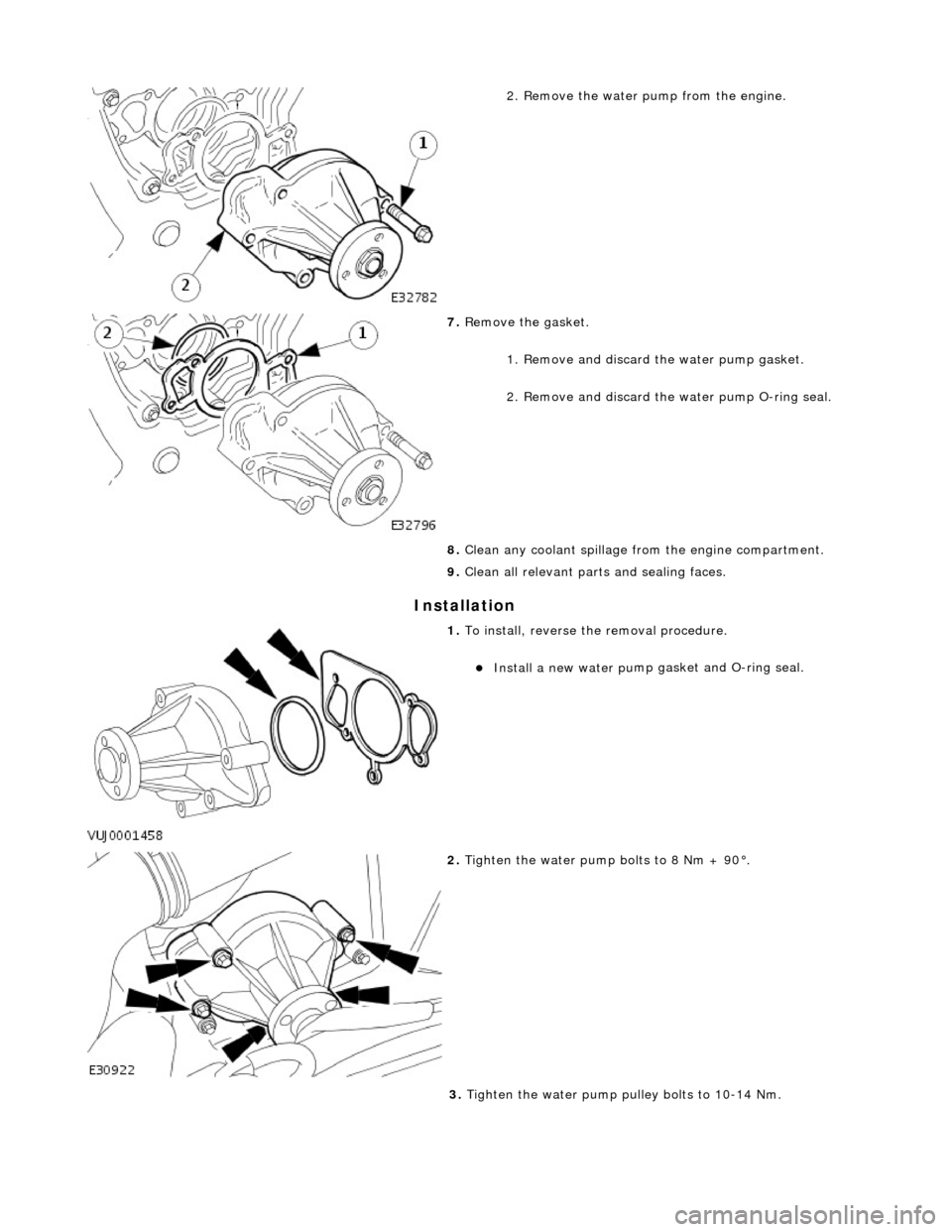
Remove the water pump from the engine.
7. Remo
ve the gasket.
1. Remove and discard the water pump gasket.
2. Remove and discard the water pump O-ring seal.
8. Clean any coolant spillage fro m the engine compartment.
9. Clean all relevant part s and sealing faces.
1. To i
nstall, reverse the removal procedure.
Install a new water
pu
mp gasket and O-ring seal.
2. Tigh ten th
e water pump bolts to 8 Nm + 90°.
3. Tighten the water pump pulley bolts to 10-14 Nm.
Page 1005 of 2490

I
nstallation
1
. Remove the five bolts wh
ich secure the water pump.
2. Remove the water pump from the engine.
8. Re
move the gasket.
1. Remove and discard the water pump gasket.
2. Remove and discard the water pump O-ring seal.
9. Clean any coolant spillage fro m the engine compartment.
10. Clean all relevant part s and sealing faces.
1. To
install, reverse the removal procedure.
Install a new water
pump gasket and O-ring seal.
2. Tigh
ten the water pu
mp securing bolts to 8 Nm + 90°.
3. Tighten the water pump pulley bolts to 10-14 Nm.
Page 1020 of 2490

Fuel Char
ging and Controls - Fuel Charging and Controls
D
iagn
osis and Testing
I
n
spection and Verification
1.
1. Veri fy the customer concern.
2. 2. Confi
rm which, if any, warning li
ghts and/or messages were displayed on the instrument cluster.
• NOTE: If any warning lights and/or me ssages were displayed when the fault occurred, refer to the Driver Information
table for DTCs associated with the display, then to the DTC index table for possible sources and actions. Some warnings will
appear to clear when the ignition is cycl ed. This is often because the warning has flagged as a resu lt of one of the vehicle's
on-board diagnostic routines having run to detect the fault. If the same routine is not run when the ignition is switched ON,
the warning will not reflag until the routine does run. See the DTC summaries for drive cycle routines.
3. 3. Visually inspect for obvious signs of mechanical or electrical damage.
Vi
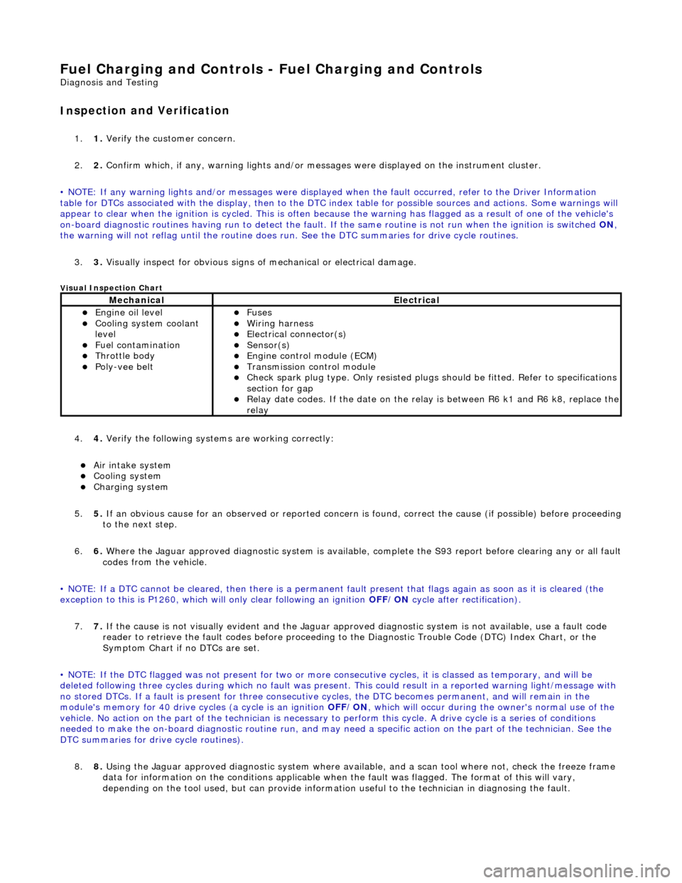
sual Inspection Chart
4.
4. Veri fy the foll
owing syst
ems are working correctly:
Air intake
system
Cooling system
Charging system
5. 5. If
an obvious cause for an observed or
reported concern is found, correct th e cause (if possible) before proceeding
to the next step.
6. 6. Where the Jaguar approved diagnostic sy stem is available, complete the S93 report before clearing any or all fault
codes from the vehicle.
• NOTE: If a DTC cannot be cleared, then there is a permanent fault present that flag s again as soon as it is cleared (the
exception to this is P1260, which will only clear following an ignition OFF/ON cycle after rectification).
7. 7. If the cause is not visually evident and the Jaguar approv ed diagnostic system is not available, use a fault code
reader to retrieve the fault codes be fore proceeding to the Diagnostic Trou ble Code (DTC) Index Chart, or the
Symptom Chart if no DTCs are set.
• NOTE: If the DTC flagged was not present for two or more co nsecutive cycles, it is classed as temporary, and will be
deleted following three cycl es during which no fault was present. This could result in a reported wa rning light/message with
no stored DTCs. If a fault is present for three consecutive cycles, the DTC becomes permanent, and will remain in the
module's memory for 40 drive cycl es (a cycle is an ignition OFF/ON, which will occur during the owner's normal use of the
vehicle. No action on the part of the technician is necessary to perform this cycle. A drive cycle is a series of conditions
needed to make the on-board diagnostic ro utine run, and may need a specific action on the part of the technician. See the
DTC summaries for drive cycle routines).
8. 8. Using the Jaguar approved diagnostic system where available, and a scan tool where not, check the freeze frame
data for information on the conditions applicable when the fault was flagged. The format of this will vary,
depending on the tool used, but can pr ovide information useful to the technician in diagnosing the fault.
MechanicalElectrical
Engine
oil level
Coo
ling system coolant
lev
el
Fuel contamination
Throttle body Poly-ve
e belt
Fu
ses
W
i
ring harness
E
l
ectrical connector(s)
Sens
o
r(s)
Engine
control module (E
CM)
Tran
s
mission control module
Check spark plu
g type. Only r
e
sisted plugs should be fitted. Refer to specifications
section for gap
Relay date codes. I
f the date on the rela
y is between R6 k1 and R6 k8, replace the
relay
Page 1049 of 2490

Accessory Drive - Accessory Drive
Description an
d Operation
Parts List
Cran
kshaft Pulley
The combined crankshaft
pulley and torsio
nal vibration damper drives a single, seve n ribbed vee belt. The belt drives all of
the engine-mounted accessories; the generator, the power assi sted steering pump, the air-conditioning compressor and the
coolant water pump.
I
dler Pulley
An i
dler pulley, on the right-hand
accessory mounting, increases the wrap-angle around the generator pulley.
Coolant Pump Drive
The coolan
t pump pulley is the
uppermost of the accessory drive pulleys. Th e coolant pump is fitted between the two
cylinder banks on the front face of the engine.
Air Conditioning Compressor Drive
Thi
s is positioned at the lowest poin
t of the front-end accessory-d rive on the left hand side accessory mounting.
It
em
Par
t Number
De
scription
1—Coo
lant Pump Drive
2—Ai
r-Conditioning Compressor Drive
3—Power Steer
ing Pump Drive
4—Au
tomatic Belt Tensioner
5—Crankshaft Pul
ley
6—Idle
r Pulley
7—Generator Dri
ve
Page 1077 of 2490

Engine Igni
tion -
Engine Ignition
D
iagnosis and Testing
I
nspection and Verification
1.
1. Veri
fy the customer concern.
2. 2. Confirm which, if any, warning li ghts and/or messages were displayed on the instrument cluster.
• NOTE: If any warning lights and/or me ssages were displayed when the fault occurred, refer to the Driver Information
table for DTCs associated with the display, then to the DTC index table for possible sources and actions. Some warnings will
appear to clear when the ignition is cycl ed. This is often because the warning has flagged as a resu lt of one of the vehicle's
on-board diagnostic routines having run to detect the fault. If the same routine is not run when the ignition is switched ON,
the warning will not reflag until the routine does run. See the DTC summaries for drive cycle routines.
3. 3. Visually inspect for obvious signs of mechanical or electrical damage.
V
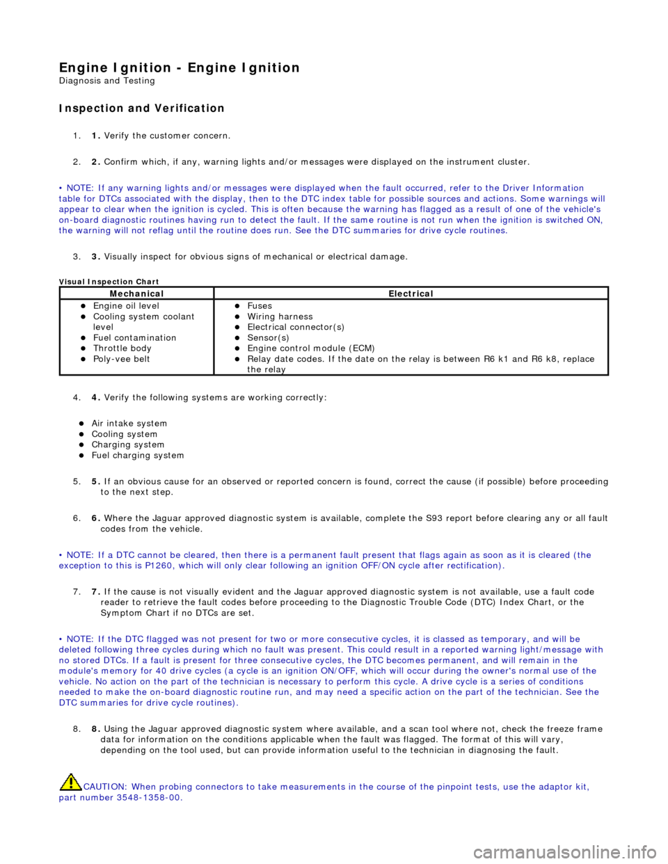
isual Inspection Chart
4.
4. Veri
fy the following syst
ems are working correctly:
Air in
take system
Coo
ling system
Charging system
F
uel charging system
5. 5. If an obvious cause for an observed or reported concern is found, correct the cause (if possible) before proceeding
to the next step.
6. 6. Where the Jaguar approved diagnostic sy stem is available, complete the S93 report before clearing any or all fault
codes from the vehicle.
• NOTE: If a DTC cannot be cleared, then there is a permanent fault present that flag s again as soon as it is cleared (the
exception to this is P1260, which will only clear following an ignition OFF/ON cycle after rectification).
7. 7. If the cause is not visually evident and the Jaguar approv ed diagnostic system is not available, use a fault code
reader to retrieve the fault codes be fore proceeding to the Diagnostic Trou ble Code (DTC) Index Chart, or the
Symptom Chart if no DTCs are set.
• NOTE: If the DTC flagged was not present for two or more co nsecutive cycles, it is classed as temporary, and will be
deleted following three cycl es during which no fault was present. This could result in a reported wa rning light/message with
no stored DTCs. If a fault is present for three consecutive cycles, the DTC becomes permanent, and will remain in the
module's memory for 40 drive cycles (a cy cle is an ignition ON/OFF, which will occur during the owner's normal use of the
vehicle. No action on the part of the technician is necessary to perform this cycle. A drive cycle is a series of conditions
needed to make the on-board diagnostic ro utine run, and may need a specific action on the part of the technician. See the
DTC summaries for driv e cycle routines).
8. 8. Using the Jaguar approved diagnostic system where available, and a scan tool where not, check the freeze frame
data for information on the conditions applicable when the fault was flagged. The format of this will vary,
depending on the tool used, but can pr ovide information useful to the technician in diagnosing the fault.
CAUTION: When probing connectors to take measurements in the course of the pinpoint tests, use the adaptor kit,
part number 3548-1358-00.
MechanicalElectrical
Engi
ne oil level
Coo
ling system coolant
level
Fuel contamination
Throttle body Poly
-vee belt
F
uses
W
iring harness
E
lectrical connector(s)
Sens
or(s)
Engine
control module (ECM)
Relay date codes.
If the date on the relay is between R6 k1 and R6 k8, replace
the relay