engine coolant JAGUAR X308 1998 2.G Manual PDF
[x] Cancel search | Manufacturer: JAGUAR, Model Year: 1998, Model line: X308, Model: JAGUAR X308 1998 2.GPages: 2490, PDF Size: 69.81 MB
Page 1087 of 2490
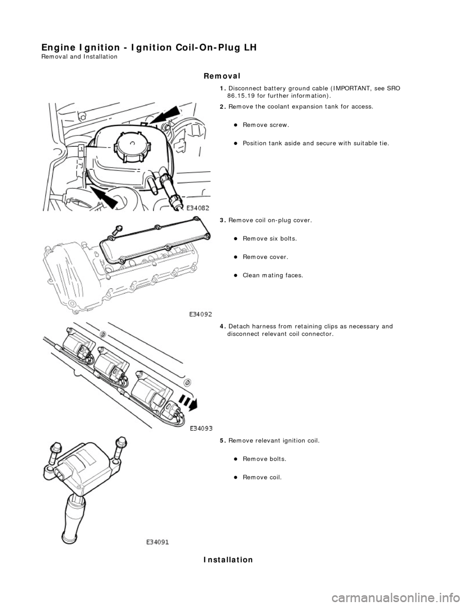
Engine Igni
tion - Ignition Coil-On-Plug LH
Re
moval and Installation
Remov
al
Installation
1. Disc
onnect battery ground cable (IMPORTANT, see SRO
86.15.19 for further information).
2. Re
move the coolant expansion tank for access.
R
emove screw.
Position tank aside an
d secu
re with suitable tie.
3. Re
move coil on-plug cover.
R
emove six bolts.
R
emove cover.
Cle
an mating faces.
4. D
etach harness from retain
ing clips as necessary and
disconnect relevant coil connector.
5. R
emove relevant ignition coil.
Re
move bolts.
Re
move coil.
Page 1094 of 2490
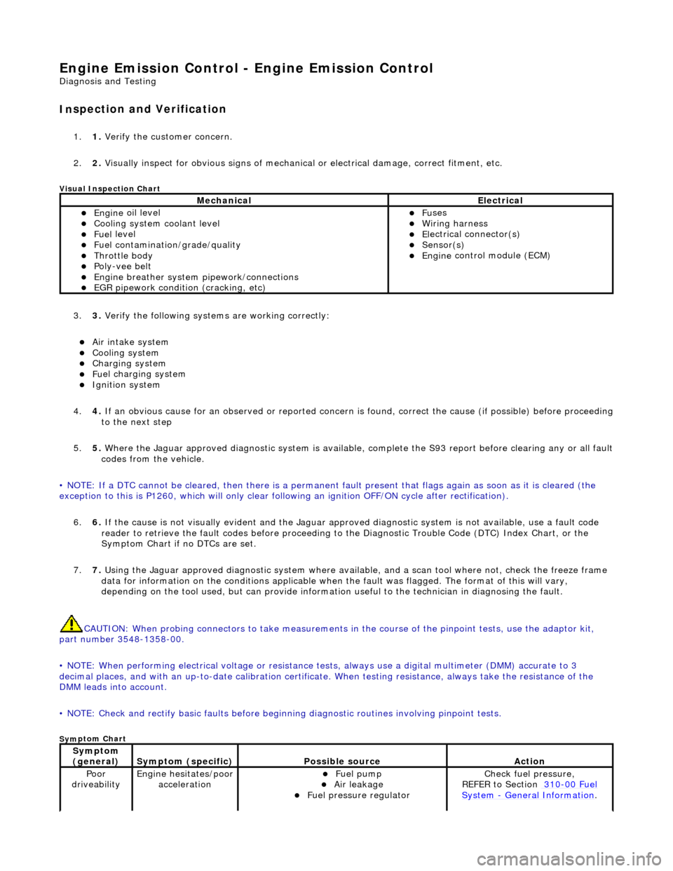
Engine Emission
Control - Engine Emission Control
D
iagn
osis and Testing
I
n
spection and Verification
1.
1. Veri fy the customer concern.
2. 2. Vis
ually inspect for obvious signs of mechanical
or electrical damage, correct fitment, etc.
Vi
sual Inspection Chart
3.
3. Veri fy the foll
owing syst
ems are working correctly:
Air intake
system
Coo
ling system
Charging system
Fu
el charging system
Ignition sys
t
em
4. 4. If an obvious cause for an observed or reported concern is found, correct the cause (if possible) before proceeding
to the next step
5. 5. Where the Jaguar approved diagnostic sy stem is available, complete the S93 report before clearing any or all fault
codes from the vehicle.
• NOTE: If a DTC cannot be cleared, then there is a permanent fault present that flag s again as soon as it is cleared (the
exception to this is P1260, which will only clear following an ignition OFF/ON cycle after rectification).
6. 6. If the cause is not visually evident and the Jaguar approv ed diagnostic system is not available, use a fault code
reader to retrieve the fault codes be fore proceeding to the Diagnostic Trou ble Code (DTC) Index Chart, or the
Symptom Chart if no DTCs are set.
7. 7. Using the Jaguar approved diagnostic system where available, and a scan tool where not, check the freeze frame
data for information on the conditions applicable when the fault was flagged. The format of this will vary,
depending on the tool used, but can pr ovide information useful to the technician in diagnosing the fault.
CAUTION: When probing connectors to take measurements in the course of the pinpoint tests, use the adaptor kit,
part number 3548-1358-00.
• NOTE: When performing electrical voltag e or resistance tests, always use a digital multimeter (DMM) accurate to 3
decimal places, and with an up-t o-date calibration certificate. When testing resistance, always take the resistance of the
DMM leads into account.
• NOTE: Check and rectify basic faults before beginning diagnostic ro utines involving pinpoint tests.
Sym
ptom Chart
MechanicalElectrical
Engi
ne
oil level
Coo
ling system coolant level
Fue
l
level
Fuel contaminatio
n
/
grade/quality
Throttle body Poly
-ve
e belt
Engine breath
er
system
pipework/connections
EGR pipework
condition (cracking, etc)
F
u
ses
W
i
ring harness
E
l
ectrical connector(s)
Sens
o
r(s)
Engine
control module (E
CM)
Sy
m
ptom
(general)
S y
mptom (specific)
Possib
l
e source
Acti
o
n
Poor
dr iveabilityEngine h e
sitates/poor
acceleration
Fue l
pump
Air leakage F
u
el pressure regulator
Chec
k fu
el pressure,
REFER to Section 310
-00 Fu
el
Sy
ste
m
- General Informati
on.
Page 1098 of 2490

Engine Emission
Control - Exhaus
t Gas Recirculation (EGR) Valve
Remo
val and Installation
Remov
a
l
1.
Re
move the engine cover.
For additional informat ion, refer to Section 501
-05
Interior
Trim and Ornamen
t
ation
.
2. Disc
onnect the evaporative emission canister purge valve
electrical connector.
3. Detac
h and reposition the evaporative emission canister purge
valve.
4. NOTE : Cap the coolan
t hose
to minimize coolant loss.
Disconnect the coolant hose.
5. Disconnect the exhaust gas recirc ulation (EGR) valve electrical
connector.
Page 1113 of 2490
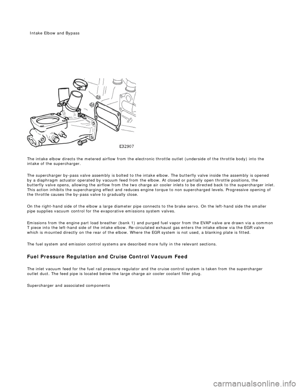
The intake elbow di
rects the metered airflow from the electronic throttle outlet (und
erside of the throttle body) into the
intake of the supercharger.
The supercharger by-pass valve assembly is bolted to the intake elbow. The butterfly valve inside the assembly is opened
by a diaphragm actuator operated by vacu um feed from the elbow. At closed or partially open throttle positions, the
butterfly valve opens, allowing th e airflow from the two charge air cooler inlets to be directed back to the supercharger inlet .
This action inhibits the supercharging e ffect and reduces engine torque to non supercharged levels. Progressive opening of
the throttle causes the by-pass valve to gradually close.
On the right-hand side of the elbow a la rge diameter pipe connects to the brake servo. On the left-hand side the smaller
pipe supplies vacuum control for the evaporative emissions system valves.
Emissions from the engine part load breather (bank 1) and pu rged fuel vapor from the EVAP valve are drawn via a common
T piece into the left-hand side of the intake elbow. Re-cir culated exhaust gas enters the intake elbow via the EGR valve
which is mounted directly on the rear of the elbow. Where the EGR system is not used, a blanking plate is fitted.
The fuel system and emission control systems are described more fully in the relevant sections.
Fuel Pressure Regula
tion and
Cruise Control Vacuum Feed
The inlet v
acuum feed fo
r the fuel rail pressure regula tor and the cruise control system is taken from the supercharger
outlet duct. The feed pipe is located below the large charge air cooler coolant filler plug.
Superchar
ger
and associated components
Inta
ke Elbow and Bypass
Page 1120 of 2490
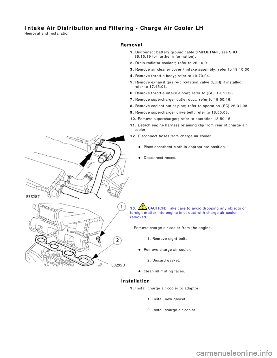
Intake Air Distribution and Filtering - Charge Air Cooler LH
Remo
val and Installation
Remov
a
l
Installation
1. Disc onne
ct battery ground cable (IMPORTANT, see SRO
86.15.19 for further information).
2. Drain radiator coolant; refer to 26.10.01.
3. Remove air cleaner cover / intake assembly; refer to 19.10.30.
4. Remove throttle body; refer to 19.70.04.
5. Remove exhaust gas re-circulation valve (EGR) if installed;
refer to 17.45.01.
6. Remove throttle intake elbo w; refer to (SC) 19.70.28.
7. Remove supercharger outlet duct; refer to 18.50.16.
8. Remove coolant outlet pipe; refe r to operation (SC) 26.31.08.
9. Remove supercharger drive belt; refer to 18.50.08.
10. Remove supercharger; refer to operation 18.50.15.
11. Detach engine harness retaining clip from rear of charge air
cooler.
12. Di
sconnect hoses from charge air cooler.
Pla
ce absorbent cloth in appropriate position.
Di
sc
onnect hoses.
13 .
CAUTI
ON: Take care to avoi
d dropping any objects or
foreign matter into engine inle t duct with charge air cooler
removed.
Remove charge air cooler from the engine.
1. Remove eight bolts.
Remove charge air cooler.
2
. Discard gasket.
Cle
a
n all mating faces.
1.
Install ch
arge air
cooler to adaptor.
1. Install new gasket.
2. Install charge air cooler.
Page 1121 of 2490
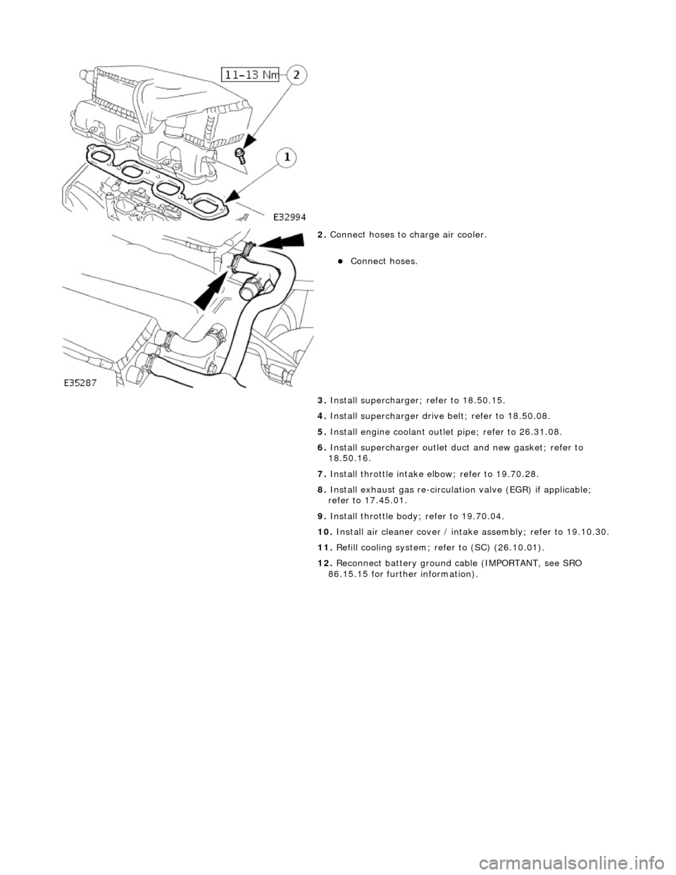
2.
Conne
ct hoses to charge air cooler.
Conne
ct hoses.
3. Install supercharger; refer to 18.50.15.
4. Install supercharger driv e belt; refer to 18.50.08.
5. Install engine coolant outlet pipe; refer to 26.31.08.
6. Install supercharger outlet du ct and new gasket; refer to
18.50.16.
7. Install throttle intake elbow; refer to 19.70.28.
8. Install exhaust gas re-circulation valve (EGR) if applicable;
refer to 17.45.01.
9. Install throttle body ; refer to 19.70.04.
10. Install air cleaner cover / intake assembly; re fer to 19.10.30.
11. Refill cooling system; refer to (SC) (26.10.01).
12. Reconnect battery ground cable (IMPORTANT, see SRO
86.15.15 for further information).
Page 1122 of 2490
Intake Air Distribution and Filtering - Charge Air Cooler RH
Remo
val and Installation
Remov
a
l
Installation
1. Disc onne
ct battery ground cable (IMPORTANT, see SRO
86.15.19 for further information).
2. Drain radiator coolant; refer to 26.10.01.
3. Remove air cleaner cover / intake assembly; refer to 19.10.30.
4. Remove throttle body; refer to 19.70.04.
5. Remove exhaust gas re-circulation valve (EGR) if installed;
refer to 17.45.01.
6. Remove throttle intake elbo w; refer to (SC) 19.70.28.
7. Remove supercharger outlet duct; refer to 18.50.16.
8. Remove coolant outlet pipe; refe r to operation (SC) 26.31.08.
9. Remove supercharger drive belt; refer to 18.50.08.
10. Remove supercharger; refer to operation 18.50.15.
11. Remove intake air temperatur e sensor 2 from charge air
cooler; refer to 18.30.52.
12. Detach engine harness retaining clip from rear of charge air
cooler.
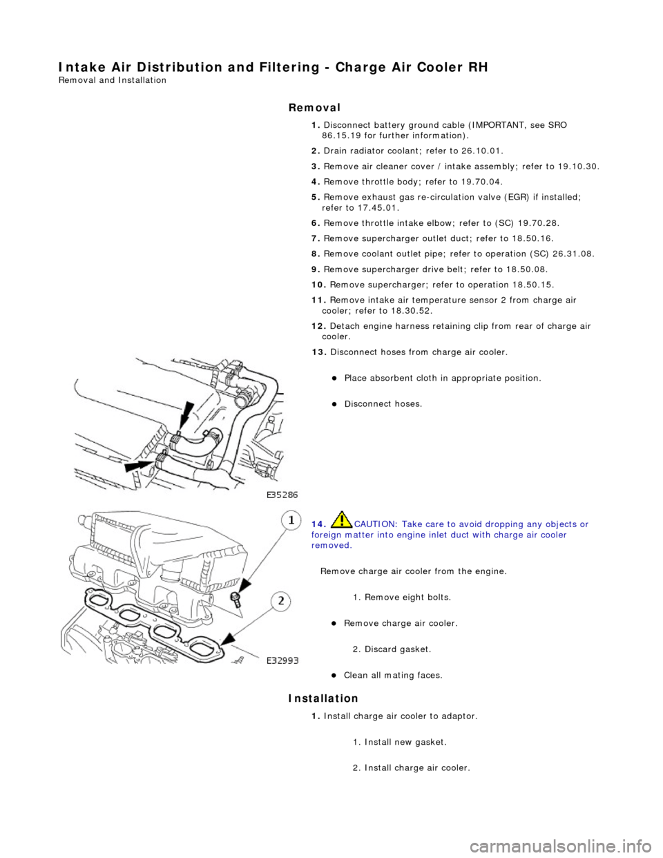
13. Di
sconnect hoses from charge air cooler.
Pla
ce absorbent cloth in appropriate position.
Di
sc
onnect hoses.
14 . CAUTI
ON: Take care to avoi
d dropping any objects or
foreign matter into engine inle t duct with charge air cooler
removed.
Remove charge air cooler from the engine. 1. Remove eight bolts.
Remove charge air cooler.
2
. Discard gasket.
Cle
a
n all mating faces.
1.
Install ch arge air
cooler to adaptor.
1. Install new gasket.
2. Install charge air cooler.
Page 1123 of 2490
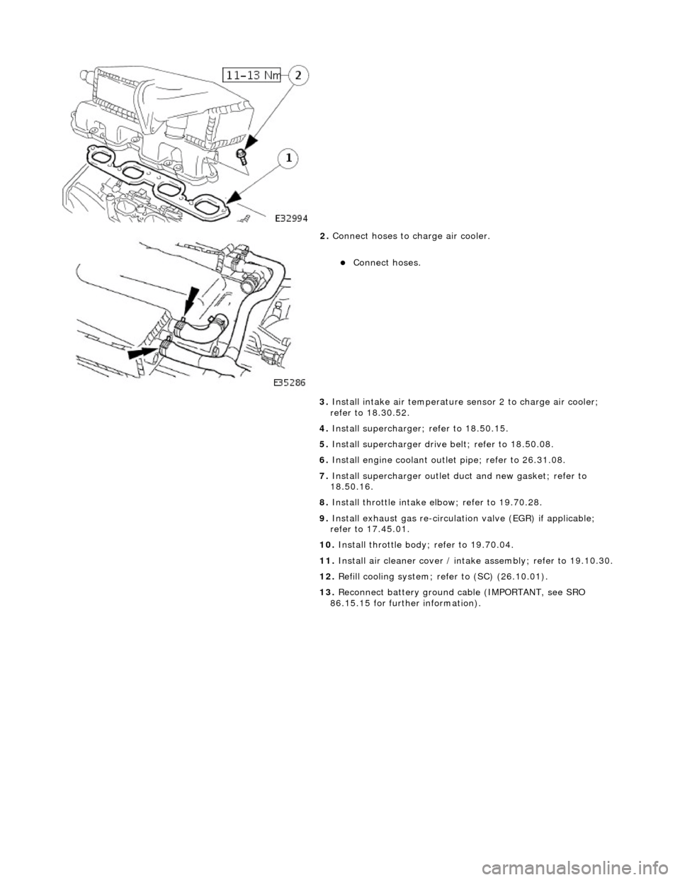
2.
Conne
ct hoses to charge air cooler.
Conne
ct hoses.
3. Install intake air te mperature sensor 2 to charge air cooler;
refer to 18.30.52.
4. Install supercharger; refer to 18.50.15.
5. Install supercharger driv e belt; refer to 18.50.08.
6. Install engine coolant outlet pipe; refer to 26.31.08.
7. Install supercharger outlet du ct and new gasket; refer to
18.50.16.
8. Install throttle intake elbow; refer to 19.70.28.
9. Install exhaust gas re-circulation valve (EGR) if applicable;
refer to 17.45.01.
10. Install throttle body; refer to 19.70.04.
11. Install air cleaner cover / intake assembly; re fer to 19.10.30.
12. Refill cooling system; refer to (SC) (26.10.01).
13. Reconnect battery ground cable (IMPORTANT, see SRO
86.15.15 for further information).
Page 1126 of 2490
Intake Air Distribution and Filtering - Charge Air Cooler Radiator
Remo
val and Installation
Remov
a
l
1.
Op
en the engine compartment and fit paintwork protection
sheets.
2. Disconnect the battery.
1. Remove the battery cover.
2. Disconnect the battery ground cable.
3. Remove the engine radiator and air conditioning condensor
assembly. Refer to operation 26.40.01.
4. Remove the grill assembly fo r access. Refer to operation
76.55.15.
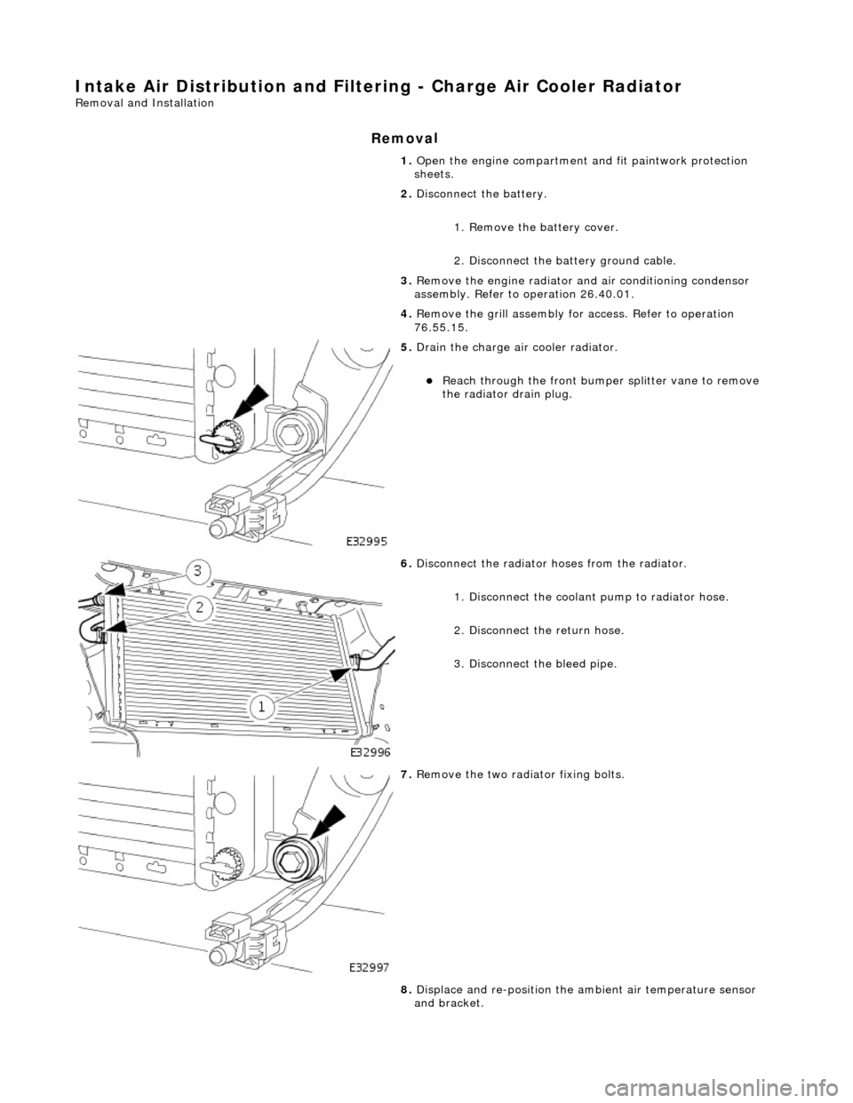
5. Drain th e charge air cooler radiator.
Reach t
hrough the front bumper
splitter vane to remove
the radiator drain plug.
6. Disc
onnect the radiator
hoses from the radiator.
1. Disconnect the coolant pump to radiator hose.
2. Disconnect the return hose.
3. Disconnect the bleed pipe.
7. Re
move the two radiator fixing bolts.
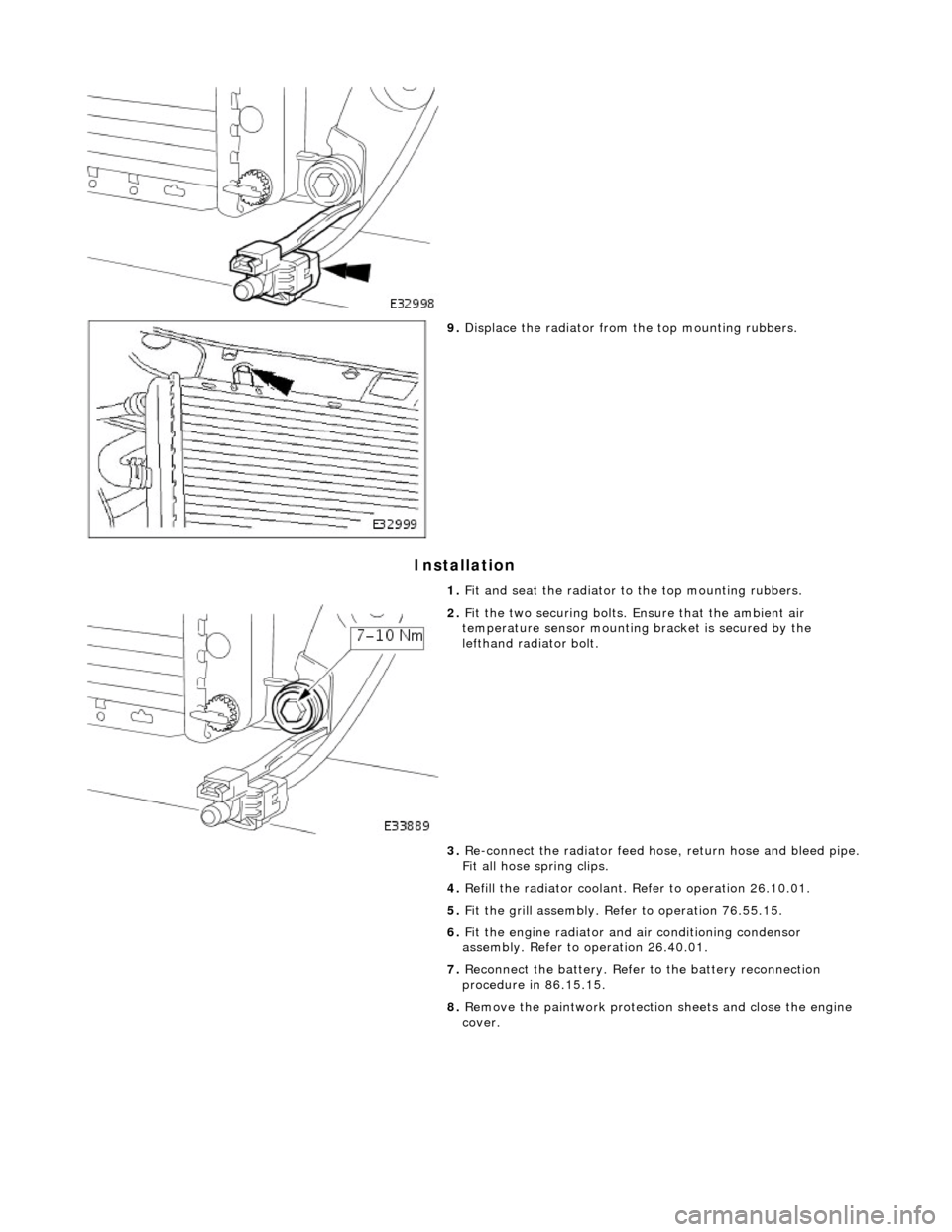
8. Displace and re-position the am bient air temperature sensor
and bracket.
Page 1127 of 2490
I
nstallation
9.
Di
splace the radiator from
the top mounting rubbers.
1. Fit and seat the radiator to the top mounting rubbers.
2. F
it the two securing bolts.
Ensure that the ambient air
temperature sensor mounting bracket is secured by the
lefthand radiator bolt.
3. Re-connect the radiator feed ho se, return hose and bleed pipe.
Fit all hose spring clips.
4. Refill the radiator coolant. Refer to operation 26.10.01.
5. Fit the grill assembly. Refer to operation 76.55.15.
6. Fit the engine radiator and air conditioning condensor
assembly. Refer to operation 26.40.01.
7. Reconnect the battery. Refer to the battery reconnection
procedure in 86.15.15.
8. Remove the paintwork protection sheets and close the engine
cover.