egr JAGUAR X308 1998 2.G Manual Online
[x] Cancel search | Manufacturer: JAGUAR, Model Year: 1998, Model line: X308, Model: JAGUAR X308 1998 2.GPages: 2490, PDF Size: 69.81 MB
Page 1271 of 2490

Controller Area Network (CAN)
The TCM is an integral part of the CAN system which facilitates the interchange of real-time data between control modules
and sensors. Please see section 303- 14 for a full description of CAN.
OBDII Interface
Data concerning OBDII related transmission failures is stored in the ECM for access via the J1962 socket.
System Functions
Range Selection
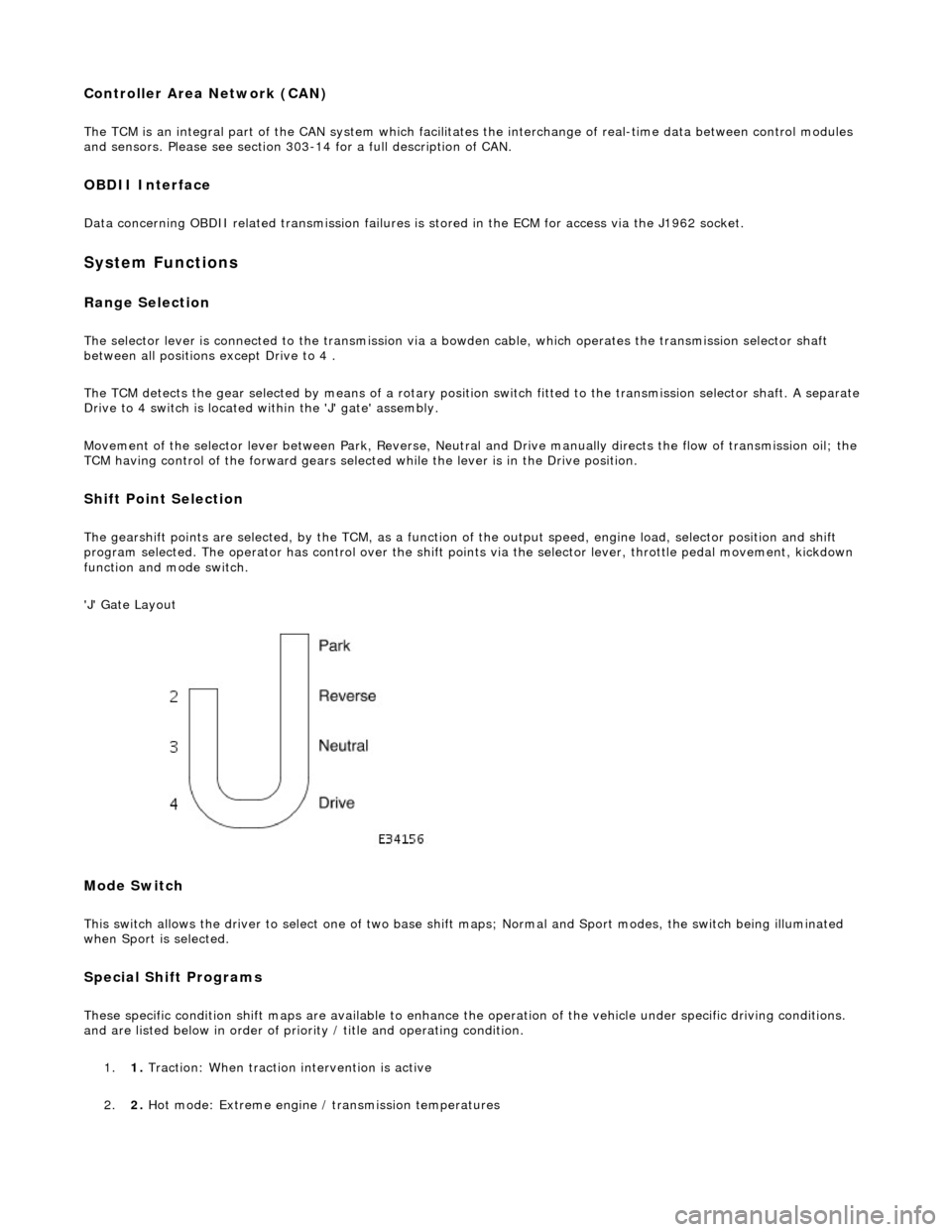
The selector lever is connected to the transmission via a bowden cable, which operates the transmission selector shaft
between all positions except Drive to 4 .
The TCM detects the gear selected by means of a rotary position switch fitted to the transmission selector shaft. A separate
Drive to 4 switch is located within the 'J' gate' assembly.
Movement of the selector lever between Park, Reverse, Neutral and Drive manually directs th e flow of transmission oil; the
TCM having control of the forward gears selected while the lever is in the Drive position.
Shift Point Selection
The gearshift points are selected, by the TCM, as a function of the output speed, engine load, selector position and shift
program selected. The operator has control over the shift points via the selector lever, throttle pedal movement, kickdown
function and mode switch.
'J' Gate Layout
Mode Switch
This switch allows the driver to select one of two base shift maps; Normal and Sport modes, the switch being illuminated
when Sport is selected.
Special Shift Programs
These specific condition shift maps are available to enhance the operation of the vehicle under specific driving conditions.
and are listed below in order of priority / title and operating condition.
1. 1. Traction: When traction intervention is active
2. 2. Hot mode: Extreme engine / transmission temperatures
Page 1362 of 2490

Automatic Transmission/Transaxle - 4.0L NA V8 - AJ27/3.2L NA V8 - AJ26
- Transmission Intern al Wiring Harness
In-vehicle Repair
Removal
• NOTE: The temperature sensor is integral with the internal harness.
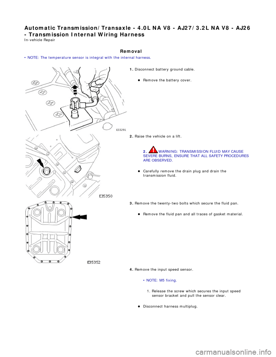
1. Disconnect battery ground cable.
Remove the battery cover.
2. Raise the vehicle on a lift.
2. WARNING: TRANSMISSION FLUID MAY CAUSE
SEVERE BURNS, ENSURE THAT ALL SAFETY PROCEDURES
ARE OBSERVED.
Carefully remove the drain plug and drain the
transmission fluid.
3. Remove the twenty-two bolts which secure the fluid pan.
Remove the fluid pan and all tr aces of gasket material.
4. Remove the input speed sensor.
• NOTE: M5 fixing. 1. Release the screw which secures the input speed sensor bracket and pull the sensor clear.
Disconnect harness multiplug.
Page 1393 of 2490

2.2. Switch OFF the ignition.
3. 3. Wait 10 seconds.
4. 4. Start the engine.
5. 5. Select R (reverse will be selected).
6. 6. Select D ( 2 will be selected).
The limp-home mode will be retained until the fault is remedied or the fault code has been erased. Intermittent faults may
be cleared by cycling the ignition OFF/ON. In certain cases the component may need to be operated before the fault code is
cleared eg. a shift solenoid.
Emergency Running (mechanica l/hydraulic limp-home mode)
Should slip be detected, due to a mechanical failure or loss of pressure, the transmission will either shift to, and hold 3 or
shift to, and hold, the last gear which was known to be alright. This condition may be cleared by cycling the ignition OFF/ON
following mechanical repair.
The operator will be made aware of certain faults by a warning message on th e instrument cluster.
Data concerning OBDII related transmission failures is stored in the ECM for access via the J1962 socket.
Safety Functions
These functions are designed to safeguard against inappropriate actions by the operator as well as system malfunctions.
The electrical and diagnostic system has been designed such that system integrity is protected at all times, the safety
concept being based on th e following three points.
1. 1. The hydraulic system has 'fail-safe' characteristics regardin g its electrical operation, such that should the power
supply be lost to the electro-hydraulic actuators the transmission will initiate a limp-home mode.
2. 2. Recognition of critical shift operation by monitoring the last element in the signal path, ie the solenoid valve, and
checking by means of redundant me asured variables relative to engine, transmission and road speeds.
3. 3. Each time the vehicle is started there is a check on the entire safety hardware and the associated program parts
and signal paths. A malfunction in this part of the system, or triggering of the safety circuit, is communicated to
the operator by a warning messag e on the instrument cluster.
CAUTION: Do not engage R or P with the vehicle in motion.
Should R be engaged with the vehicle in forward motion, the transmission will default to neutral until either the vehicle
speed decreases to 4 mph or D is selected.
Towing
The vehicle may be towed provided that:
Selector in position N Speed < 50 kph Distance < 50 km
System Functions
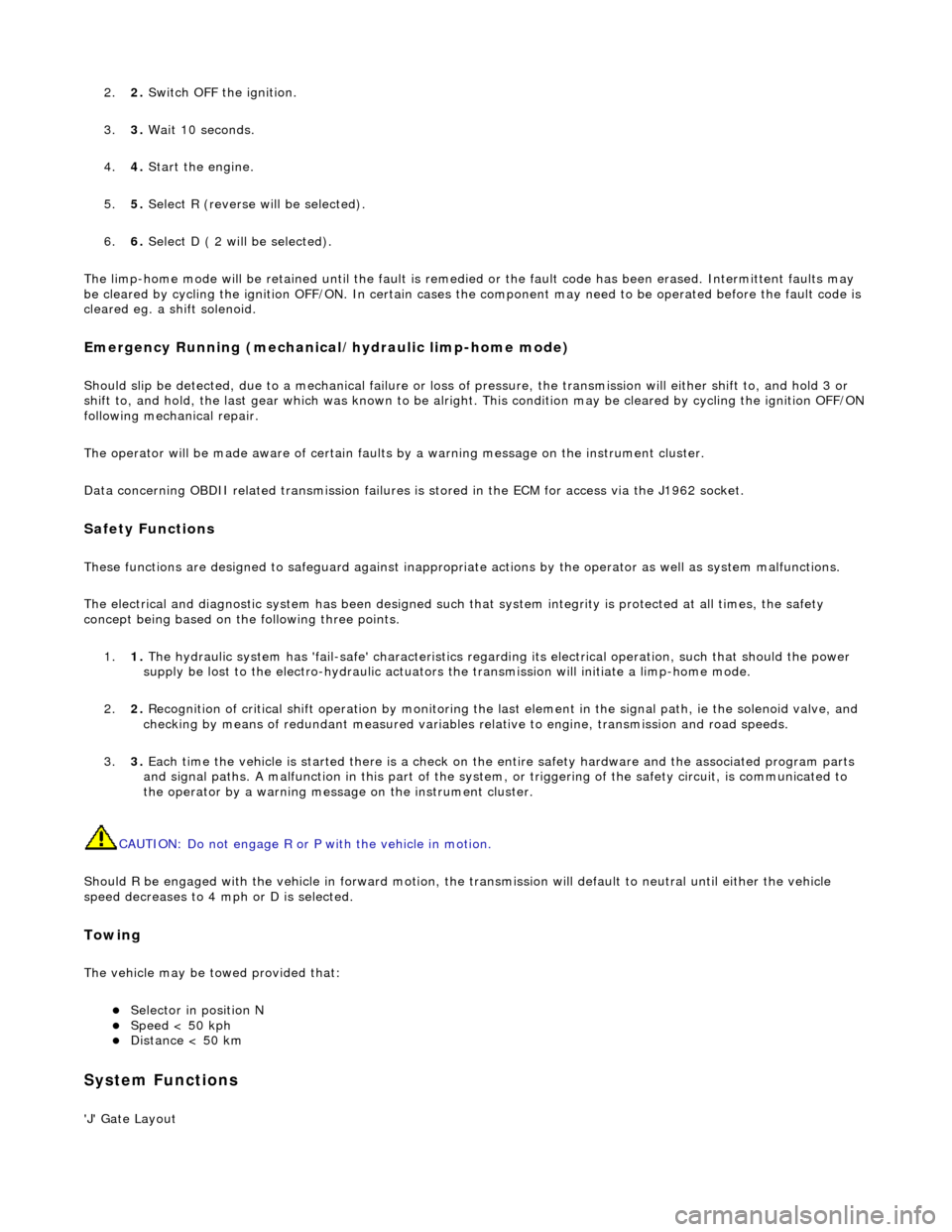
'J' Gate Layout
Page 1395 of 2490

and/or increased performance as appropriate.
Serial Communications Interfaces
Controller Area Network (CAN)
The TCM is an integral part of the CAN system which facilita tes the interchange of real-time data between control modules
and sensors; refer to 303-14 fo r a full description of CAN.
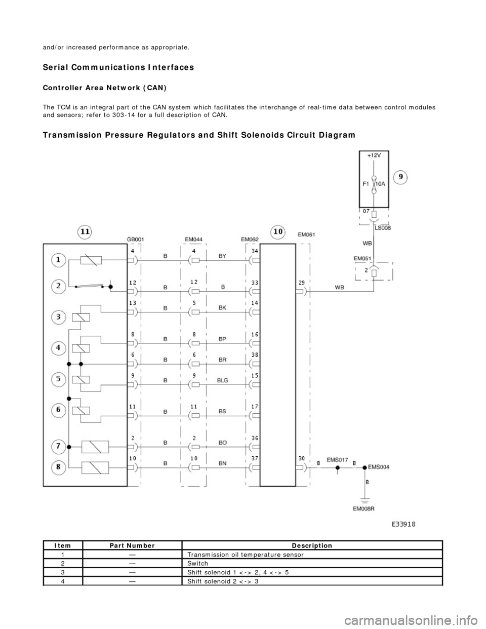
Transmission Pressure Regulators and Shift Solenoids Circuit Diagram
ItemPart NumberDescription
1—Transmission oil temperature sensor
2—Switch
3—Shift solenoid 1 <-> 2, 4 <-> 5
4—Shift solenoid 2 <-> 3
Page 1527 of 2490

Rear Muffler Assembly
The left-hand and right-hand rear muffler assemblies comprise:
Absorption type muffler. Inlet pipe and tailpipe welded to the muffler. Tailpipe bright finisher integral with the tailpipe.
Tailpipe Clearance to Moulded Bumper
Page 1597 of 2490

Pinpoint test F: P0153
With EM010 and EM015 disconnected, measure the
voltage between EM010/023 and EM015/001. 1
Is the voltage B+?
Yes Remove link lead and reconnect all connectors.
GO to E18
No Check integrity of EMS fuse F1 4, EMS control relay (relay
1) is energized and all connections are made.
GO to E18
E18: END
Perform appropriate service drive cycle and check for the
presence of DTC. 1
Has the fault code cleared?
Yes STOP
No Contact Jaguar Service
PINPOINT TEST F : P0153
TEST CONDITIONSDETAILS/RESULTS/ACTIONS
F1: RETRIEVE DTCS
• NOTE: Battery and or ECM disconnection prior to scanning wi ll erase all data, ensure that the correct DTC is present.
Page 1609 of 2490

Pinpoint test G: P0157, P0158
With EM010 and EM015 disconnected, measure the
voltage between EM010/023 and EM015/002. 1
Is the voltage B+?
Yes Remove link lead and reconnect all connectors.
GO to F19
No Check integrity of EMS fuse F1 4, EMS control relay (relay
1) is energized and all connections made.
GO to F19
F19: END
Perform appropriate service drive cycle and check for the
presence of DTC. 1
Has the fault code cleared?
Yes STOP
No Contact Jaguar Service
PINPOINT TEST G : P0157, P0158
TEST CONDITIONSDETAILS/RESULTS/ACTIONS
G1: RETRIEVE DTCS
• NOTE: Battery and or ECM disconnection prior to scanning wi ll erase all data, ensure that the correct DTC is present.
Page 1692 of 2490

Fuel Tank and Lines - Fuel Tank and Li
nes
Description an
d Operation
Fuel Tank
Parts List
The steel fuel tank is located inside the trunk and mounted across the vehicle behind the passenger compartment bulkhead.
The fuel tank is held in posi tion by two retaining straps fi tted to body-mounted brackets.
The fuel tank has an integral non-adjustable fill er pipe and integral breather and vapor pipework.
A single fuel pump is mounted inside the tank on vehicles with normally aspirated engines. For vehicles with supercharged
engines, two pumps are fitted in the tank. Fuel is drawn by the pump(s) from the fuel tank and supplied via the fuel lines
and 70 micron filter to the fuel rails.
The fuel lines run from front-to-rear down the vehicle's left-hand-side.
Ite
m
Part
Number
Descr
iption
1—Fu
el filler latch box
2—Pressure reli
ef pipe, ORVR
(shown) / tank breather pipe on non-ORVR systems
3—Tank grounding
cable
4—Evaporative flan
ge assembly
(ORVR type shown)
5—Trunk elec
trical harne
ss (part of)
6—Fue
l
level sensor
flange/connector
7—Fu
el tank retaining straps
8—F
u
el tank retaining stra
ps adjustable clamps
9—Fu
el tank retaining straps lower brackets
10—Tank vapor outlet pipe to un
derflo
or pipe quick-fit connector
11—F
u
el filler latch bo
x water drain pipe
Page 1699 of 2490

Conne
ct the scan tool
1
Have the DTC(s) and fr
eeze
frame data been recorded?
Yes GO to A2
A2
: CHECK FUSE
•
NOTE: See further steps for poss
ible cause of fuse failure.
Chec
k fuse F7 integrity (located in the trunk).
1
OK
?
Yes GO to A3
No Renew fuse and test the syst em for normal operation.
A3:
CHECK SHORT TO SUPPLY
Page 1713 of 2490

Conne
ct the scan tool
1
Have the DTC(s) and fr
eeze
frame data been recorded?
Yes GO to B2
B2
: CHECK FUSE
•
NOTE: See further steps for poss
ible cause of fuse failure.
Chec
k fuse 15 integrity (located in the trunk)
1
OK
?
Yes GO to B3
No Renew fuse and test the syst em for normal operation.
B3:
CHECK SHORT TO SUPPLY