Starter relay JAGUAR X308 1998 2.G Workshop Manual
[x] Cancel search | Manufacturer: JAGUAR, Model Year: 1998, Model line: X308, Model: JAGUAR X308 1998 2.GPages: 2490, PDF Size: 69.81 MB
Page 528 of 2490
Speed an
d load
Coo
l
ant temperature
Ti
me el
apsed from start up
Cl
osed l
oop fuelling
Determination of the vapour concentration is made by stepped opening of the EVAP valve and subsequent monitoring of the
fuelling correction. This function is performed prior to purging, so that at the onse t of purging the EVAP valve can be set to
the optimum position. Should the ECM be unable to determine the concentration before purging, a default value is
employed, which is then modified whilst purging is in progress.
When the purging process is operational th e ECM modifies the basic fuelling calculation to maintain the correct air / fuel
ratio.
Purging is inhibited during fuel cut-off and stability / traction control intervention.
Coolant Temperature Sen
sor
Th
e
sensor outputs a voltage to the ECM which decreases as temperature increases.
Cooling Fans
In response to engi
ne coolant temperat
u
re and climate control system demand, the ECM will energize the cooling fans.
Climate Control Compressor
The E
C
M will allow the compressor clutch to be engaged if th
e engine temperature and load demand are normal. Should the
driver require maximum engine powe r or the coolant temperature be high, the request will be denied.
Cranking Signal
The ECM reacts to a signal fr
om th
e Body Processor Module (BPM) when the starter motor relay is energi
zed. This signal is
used to trigger starting, fu el and ignition strategies.
Engine Speed and Cranksh
aft Position
Engine
speed and cran
k position are moni
tored by a sensor which is mounted on the cylinder block (flywheel housing)
behind the crankshaft drive plat e. It indicates rotational speed to the ECM in the form of 12 pulses per crank revolution.
Engine speed is used for synchronization of fuel an d ignition systems, as well as other functions.
Camshaft Position
The ca
mshaft position sensor is mounted at
the rear of Bank 2 cylinder head on the inlet side and provides one signal every
720 degrees of crankshaft rotation. The signal, in conjunction with the signal from the crankshaft position sensor, indicates
to the ECM that the piston of cylinder 1A is approaching TDC on the compression stroke.
Variable Valve
Timing (Where Fitted)
By energi
si
ng a solenoid to allow the pass
age of pressurized oil on each of the inle t camshaft drives, the ECM can vary by a
single stepped amount, the relati ve timing of the inlet valves.
Ign
ition
Ignit
i
on spark is produced by
individual on-plug coil units.
There are two ignition amplifiers; module #1 drives coils 1A, 2B, 3B and 4A, whilst module #2 drives coils 1B, 2A, 3A and
4B. The ECM controls the amplifiers.
Page 1062 of 2490
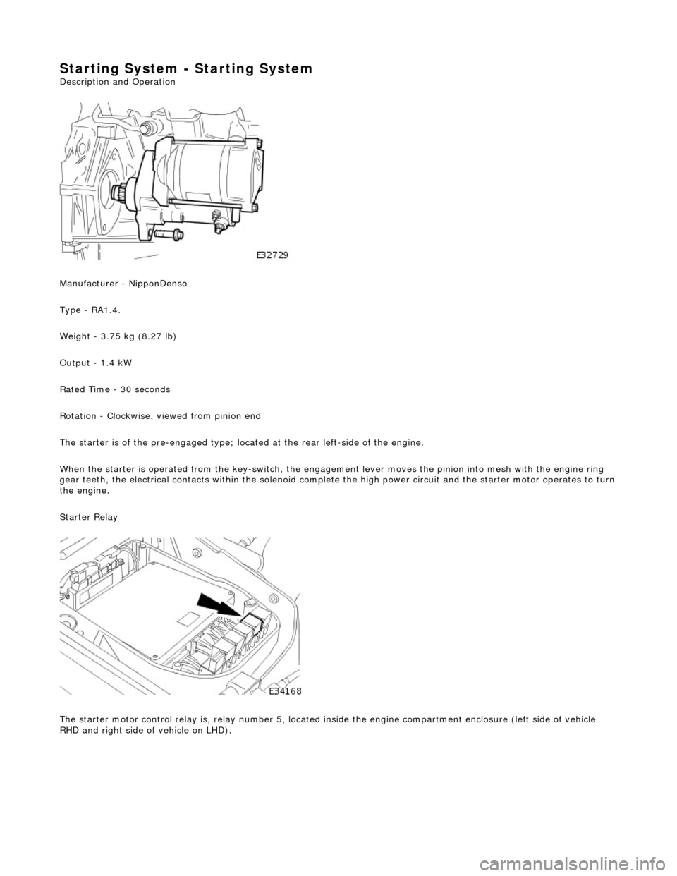
Starting System - Starting System
Description and Operation
Manufacturer - NipponDenso
Type - RA1.4.
Weight - 3.75 kg (8.27 lb)
Output - 1.4 kW
Rated Time - 30 seconds
Rotation - Clockwise, viewed from pinion end
The starter is of the pre-engaged type; loca ted at the rear left-side of the engine.
When the starter is operated from the key-switch, the engagement lever moves the pinion into mesh with the engine ring
gear teeth, the electrical contacts within the solenoid complete the high power circuit and the starter motor operates to turn
the engine.
Starter Relay
The starter motor control relay is, relay nu mber 5, located inside the engine compartment enclosure (left side of vehicle
RHD and right side of vehicle on LHD).
Page 1064 of 2490
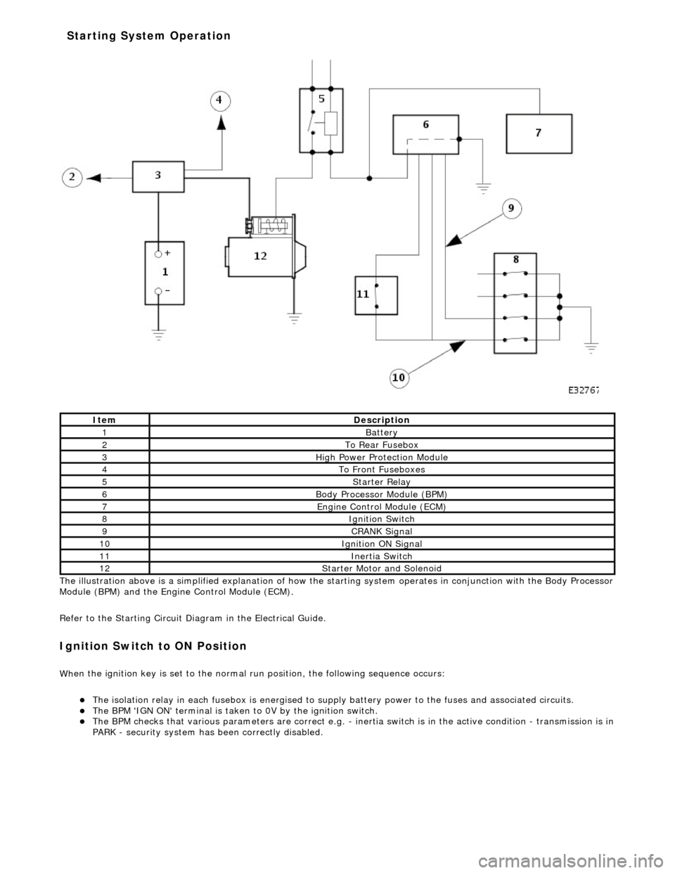
The il
lustration above is a simplified expl
anation of how the starting system operates in conjunction with the Body Processor
Module (BPM) and the Engine Control Module (ECM).
Refer to the Starting Circuit Diagram in the Electrical Guide.
I g
nition Switch to ON Position
W
h
en the ignition key is set to the normal run position, the following sequence occurs:
The
is
olation relay in each fusebox is
energised to supply battery power to the fuses and associated circuits.
The BPM 'IGN
ON' terminal
is taken to 0V by the ignition switch.
The BPM
checks that various parameters are correct e.g. -
inertia switch is in the active condition - transmission is in
PARK - security system has been correctly disabled.
It e
m
De
scr
iption
1Batt
ery
2To Re ar
Fusebox
3Hi
gh Power Pr
otection Module
4To Front
Fu
seboxes
5Starter Re
lay
6Body Processor M
odule (BPM)
7Engine
C
ontrol Module (ECM)
8Ignition Switch
9CRANK Signal
10Ignition ON Signal
11Inertia Switch
12St
arte
r Motor and Solenoid
Starting System Operation
Page 1065 of 2490
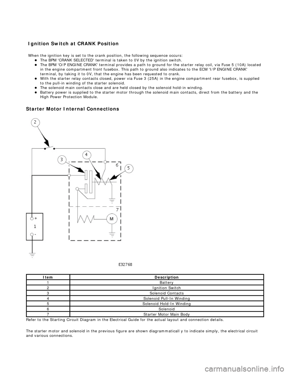
The BPM
'CRANK SELECTED' terminal is ta
ken to 0V by the ignition switch.
The BPM
'O/P ENGINE CRANK' terminal pr
ovides a path to ground for the starte r relay coil, via Fuse 5 (10A) located
in the engine compartment front fusebo x. This path to ground also indicates to the ECM 'I/P ENGINE CRANK'
terminal, by taking it to 0V, that the engine has been requested to crank.
Wi
th the starter relay contacts closed,
power via Fuse 3 (25A) in the engine compartment rear fusebox, is supplied
to the pull-in winding of the starter solenoid.
The s
olenoid main contacts close and are held
closed by the solenoid hold-in winding.
Battery power is supplied
to
the starter motor through the solenoid main contacts, direct from the battery and the
High Power Protection Module.
Starter
Motor Internal Connections
Re
fer to the Starting Circuit Diagram in the Electrical
Guide for the actual layout and connection details.
The starter motor and solenoid in the previous figure are shown diagrammaticall y to indicate simply, the electrical circuit
and various connections.
It
em
De
scription
1Batt
ery
2Ignition Switch
3So
lenoid Contacts
4So
lenoid Pull-In Winding
5So
lenoid Hold-In Winding
6So
lenoid
7St
arter Motor Main Body
I
gnition Switch at CRANK Position
W
hen the ignition key is set to the crank position, the following sequence occurs:
Page 1066 of 2490
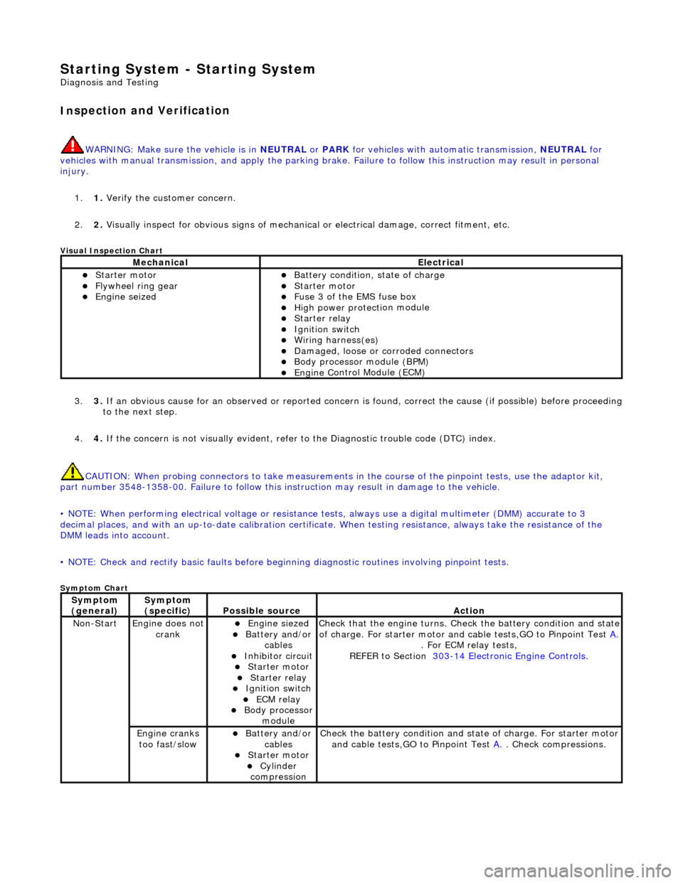
Starting System - Starting System
Diagn
osis and Testing
I
n
spection and Verification
W
A
RNING: Make sure
the vehicle is in NEUTRAL or PARK for vehicles with au tomatic transmission, NEUTRAL for
vehicles with manual transmissi on, and apply the parking brake. Failure to foll ow this instruction may result in personal
injury.
1. 1. Verify the customer concern.
2. 2. Visually inspect for obvious signs of mechanical or electrical damage, correct fitment, etc.
Vi
sual Inspection Chart
3.
3. If an obvi
ous cause for an observed or
reported concern is found, correct th e cause (if possible) before proceeding
to the next step.
4. 4. If the concern is not visually evident, refer to the Diagnostic trouble code (DTC) index.
CAUTION: When probing connectors to take measurements in the course of the pinpoint tests, use the adaptor kit,
part number 3548-1358-00. Failure to follow this in struction may result in damage to the vehicle.
• NOTE: When performing electrical voltag e or resistance tests, always use a digital multimeter (DMM) accurate to 3
decimal places, and with an up-t o-date calibration certificate. When testing resistance, always take the resistance of the
DMM leads into account.
• NOTE: Check and rectify basic faults before beginning diagnostic ro utines involving pinpoint tests.
Sym
ptom Chart
MechanicalElectrical
Starte
r motor
Flywheel
ring gear
Engine
s
eized
Batter
y condition, state of charge
Starte
r motor
F
u
se 3 of the EMS fuse box
High
power protec ti
on module
Starter relay Ignition switc
h
W
i
ring harness(es)
Damaged, loose or corroded connector
s
Body processor module (B
PM)
Engine
C
ontrol Module (ECM)
Sy
m
ptom
(
gene r
al)
Sy
m
ptom
(specific)
Possib l
e source
Acti
o
n
No
n
-Start
Engine does
not
crankEngine s
iezed
Batt
ery and
/or
cables
Inhibitor circuit St arte
r motor
Starter relay Ignition switc
h
ECM relay Body processor
modu le
Check that
the engine turns. Check the battery condition and state
of charge. For starter motor and ca ble tests,GO to Pinpoint Test A.
. For ECM relay
tests,
REFER to Section 303
-14
Electronic Engine Controls
.
Engine
c
ranks
too fast/slow
Batt ery and
/or
cables
St arte
r motor
Cy
linder
com
pression
Check the battery con
dition
and st
ate of charge. For starter motor
and cable tests,GO to Pinpoint Test A.
. Chec
k compressions.
Page 1067 of 2490
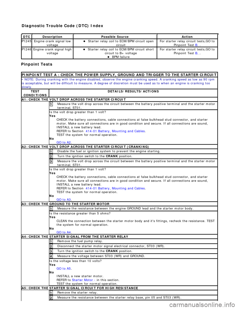
Pinpoint Tests
DT
C
De
scription
Possib
le Source
Acti
on
P1245Engine
crank signal low
voltage
Starter relay
coil to
ECM/BPM circuit open
circuit
F
or starter relay circuit tests,GO to
Pinpoint Test B.
.
P1246Engine
crank signal high
voltage
Starter relay
coil to ECM/BPM circuit short
circuit to B+ voltage
B
PM failure
F
or starter relay circuit tests,GO to
Pinpoint Test B.
.
P
INPOINT TEST A : CHECK THE
POWER SUPPLY, GROUND AND TRI GGER TO THE STARTER CIRCUIT
•
NOTE: During cranking with the engine disabled, observe the engine cranking speed. A cranking speed as low as 90 rpm
is acceptable, but will be difficult to measure. A degree of discretion must be used as to when an engine is cranking too
slowly.
TE
ST
CONDITIONS
D
ETAILS/RESULTS/ACTIONS
A1: CHECK
THE VOLT DROP AC
ROSS THE STARTER CIRCUIT
M
easure the volt drop across the circuit between the battery positive terminal and the starter motor
terminal, ST01.
1
Is the vol
t drop greater than 1 volt?
Yes CHECK the battery connections, cable connections at false bulkhead stud connector, and starter
motor. Make sure all connections are in good co ndition and secure. If all connections are sound,
INSTALL a new battery lead.
REFER to Section 414
-0
1 Battery, Mounting and Cables
.
TEST the system
for normal operation.
No GO to A2
.
A2: CHECK
THE VOLT DROP ACROSS
THE STARTER CIRCUIT (CRANKING)
Di
sable the fuel or ignition system to prevent the engine starting.
1
Turn the ignition swi
tch to the CRANK
position.
2
M
easure the volt drop across the circuit between the battery positive terminal and the starter motor
terminal, ST01.
3
Is the vol
t drop greater than 1 volt?
Yes CHECK the battery connections, cable connections at false bulkhead stud connector, and starter
motor. Make sure all connections are in good co ndition and secure. If all connections are sound,
INSTALL a new battery lead.
REFER to Section 414
-0
1 Battery, Mounting and Cables
.
TEST the system
for normal operation.
No GO to A3
.
A3:
CHECK THE GROUND TO THE STARTER MOTOR
Meas
ure the resistance between the engine GROUND lead and the starter motor body.
1
Is th
e resistance greater than 5 ohms?
Yes CLEAN the connection between the starter motor body and it's fittings, recheck the resistance. TEST
the system for normal operation.
No GO to A4
.
A4
: CHECK THE STARTER SIGNAL FROM THE STARTER RELAY
R
emove the fuel pump relay.
1
Di
sconnect the starter motor signal
electrical connector, ST03 (WR).
2
Turn the ignition swi
tch to the CRANK
position.
3
M
easure the voltage between ST03 (WR) and GROUND.
4
Is th
e voltage less than 10 volts?
Yes GO to A5
.
No
INSTALL a new starter motor.
REFER to Starter Motor
-
in t
his section.
TEST the system for normal operation.
A5
: CHECK THE STARTER SIGNAL CIRCUIT FOR HIGH RESISTANCE
R
emove the starter relay.
1
Meas
ure the resistance between the st
arter relay base, pin 05 and ST03 (WR).
2
Diagnostic Trouble Code (D
TC) Index
Page 1068 of 2490
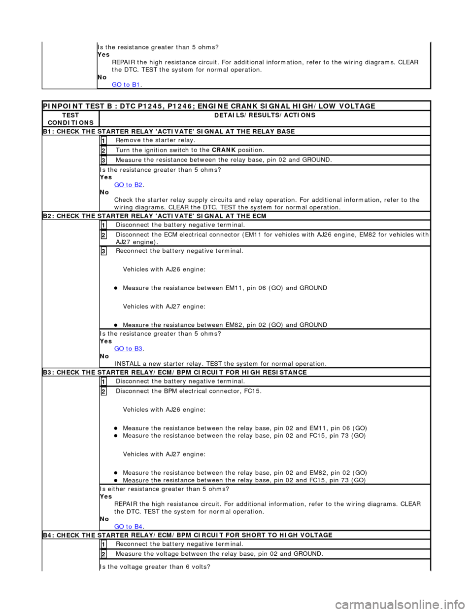
Is the res
istance greater than 5 ohms?
Yes REPAIR the high resistance circui t. For additional information, refer to the wiring diagrams. CLEAR
the DTC. TEST the system for normal operation.
No GO to B1
.
PINPOINT TES
T B : DTC P1245, P1246; ENGINE CRANK SIGNAL HIGH/LOW VOLTAGE
TE
S
T
CONDITIONS
D E
TAILS/RESULTS/ACTIONS
B1: CHECK
THE STARTER
RELAY 'ACTIV
ATE' SIGNAL AT THE RELAY BASE
Re
move the starter relay.
1
Turn the ignition swi
t
ch to the CRANK
position.
2
Measure t
he resistance between th
e relay base, pin 02 and GROUND.
3
Is the res
istance greater than 5 ohms?
Yes GO to B2
.
No Check t
he starter relay supply circui
ts and relay operation. For additi onal information, refer to the
wiring diagrams. CLEAR the DTC. TEST the system for normal operation.
B2: CHECK THE STARTER
RELAY 'A
CTIVATE' SIGNAL AT THE ECM
Disc
onnect the battery negative terminal.
1
D
i
sconnect the ECM electrical connector (EM11 for vehicles with AJ26 engine
, EM82 for vehicles with
AJ27 engine).
2
R e
connect the battery negative terminal.
Vehicles with AJ26 engine:
Meas ure t
he resistance between EM11, pin 06 (GO) and GROUND
Vehicles with AJ27 engine:
Meas ure t
he resistance between EM82, pin 02 (GO) and GROUND
3
Is th
e res
istance greater than 5 ohms?
Yes GO to B3
.
No
IN
STALL a new starter relay. TEST
the system for normal operation.
B3: CHECK THE STARTER
RELAY/ECM/BPM CIRCUIT FOR HIGH RESISTANCE
Di sc
onnect the battery negative terminal.
1
Disc
onne
ct the BPM electrical connector, FC15.
Vehicles with AJ26 engine:
Meas ure t
he resistance between the relay
base, pin 02 and EM11, pin 06 (GO)
Measure t
he resistance between the relay
base, pin 02 and FC15, pin 73 (GO)
Vehicles with AJ27 engine:
Meas ure t
he resistance between the relay
base, pin 02 and EM82, pin 02 (GO)
Measure t
he resistance between the relay
base, pin 02 and FC15, pin 73 (GO)
2
Is either resistance greater
than 5 ohms?
Yes REPAIR the high resistance circui t. For additional information, refer to the wiring diagrams. CLEAR
the DTC. TEST the system for normal operation.
No GO to B4
.
B4: CHECK THE STARTER
RE
LAY/ECM/BPM CIRCUIT FOR SHORT TO HIGH VOLTAGE
Re
connect the battery negative terminal.
1
Meas
ure t
he voltage between the
relay base, pin 02 and GROUND.
2
Is the volt
age greater than 6 volts?
Page 1190 of 2490
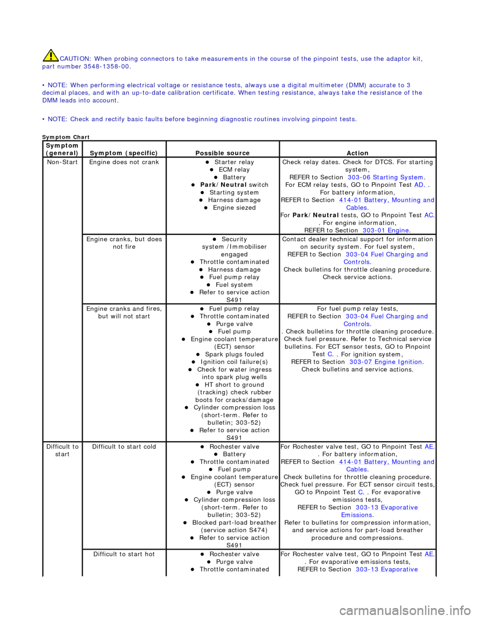
CAUTIO
N: When probing connectors to take
measurements in the course of the pinpoint tests, use the adaptor kit,
part number 3548-1358-00.
• NOTE: When performing electrical voltag e or resistance tests, always use a digital multimeter (DMM) accurate to 3
decimal places, and with an up-t o-date calibration certificate. When testing resistance, always take the resistance of the
DMM leads into account.
• NOTE: Check and rectify basic faults before beginning diagnostic ro utines involving pinpoint tests.
Sym
ptom Chart
Sym
ptom
(general)
S y
mptom (specific)
Possib
l
e source
Acti
o
n
No
n
-Start
Engine
does not cran
k
Starter relay ECM relay Batt
ery Park
/Neutral
switch
Starting system
Harness damage
Engine s
iezed
Check r
e
lay dates. Check
for DTCS. For starting
system,
REFER to Section 303
-06 Sta r
ting System
.
F or ECM
relay tests, GO to Pinpoint Test
AD.
.
F o
r battery information,
REFER to Section 414
-0 1
Battery, Mounting and
Cables.
Fo r
Park/Neutral tests, GO to Pinpoint Test AC.
. Fo
r engine information,
REFER to Section 303
-01 En
gine
.
Engine cranks, but does
not fireSecurity
syst
em /Immobiliser
engaged
Thr o
ttle contaminated
Harness damage
Fu
el pump relay
Fue
l
system
R
e
fer to service action
S491
Contact dealer techni
cal
support for information
on security system. For fuel system,
REFER to Section 303
-0 4
Fuel Charging and
Controls.
Check bull etins for throttl
e cleaning procedure.
Check service actions.
Engine cranks an d
fires,
but will not start
F u
el pump relay
Thr
o
ttle contaminated
Purge
val
ve
Fue
l
pump
Engine coolan
t
temperature
(ECT) sensor
Spark plugs
fouled
Ignition coil
fail
ure(s)
Check f
o
r water ingress
into spark plug wells
HT sh o
rt to ground
(tracking) check rubber
boots for cracks/damage
Cyli
nder compression loss
(short-term. Refer to bulletin; 303-52)
Re
fer to service action
S491
Fo
r fuel pump relay tests,
REFER to Section 303
-0 4
Fuel Charging and
Controls.
. Check bulletins for throttl
e cleaning procedure.
Check fuel pressure. Refe r to Technical service
bulletins. For ECT sensor tests, GO to Pinpoint Test C.
. Fo
r ignition system,
REFER to Section 303
-07 En
gine Ignition
.
Check bulletins an d service a
ctions.
Di
f
ficult to
start
D iff
icult to start cold
Roc
h
ester valve
Batt
ery Thro
ttle contaminated
Fue
l
pump
Engine coolan
t
temperature
(ECT) sensor
Purge val
ve
Cyl
i
nder compression loss
(short-term. Refer to bulletin; 303-52)
Blocked part-load breather (s
ervice action S474)
R
e
fer to service action
S491
For R
ochester valv
e test, GO to Pinpoint Test AE.
. Fo
r battery information,
REFER to Section 414
-0 1
Battery, Mounting and
Cables.
Check bull etins for throttl
e cleaning procedure.
Check fuel pressure. For ECT sensor circuit tests,
GO to Pinpoint Test C.
. F
or evaporative
emissions tests,
REFER to Section 303
-1 3
Evaporative
Emiss
i
ons
.
R e
fer to bulletins for co
mpression information,
and service actions for part-load breather procedure and compressions.
Diff
icult to start hot
Roc
h
ester valve
Purge
val
ve
Thr
o
ttle contaminated
F
or R
ochester valv
e test, GO to Pinpoint Test AE.
. F
or evaporative emissions tests,
REFER to Section 303
-1 3
Evaporative
Page 1191 of 2490
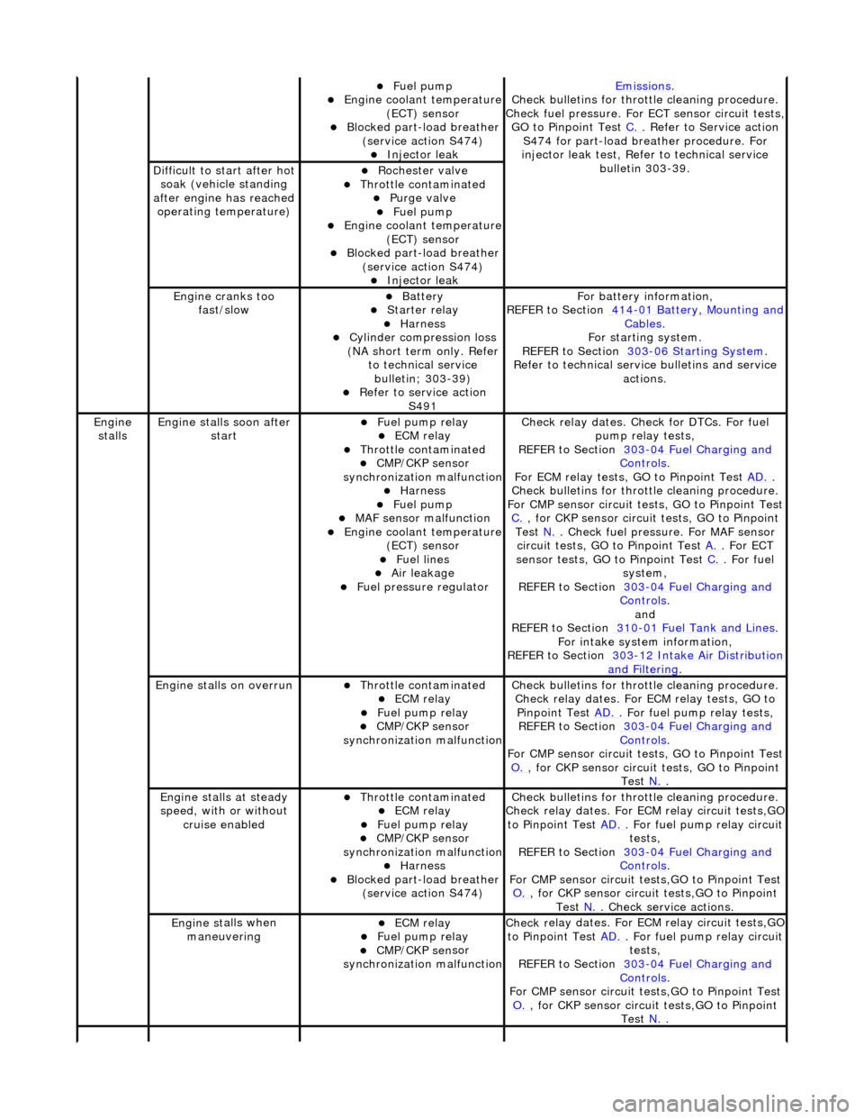
Fue
l pump
Engine coolan
t temperature
(ECT) sensor
Blocked part-load breather (
service action S474)
Injec
tor leak
Emiss
ions
.
Check bull
etins for throttle cleaning procedure.
Check fuel pressure. For ECT sensor circuit tests,
GO to Pinpoint Test C.
. Refer to Servi
ce action
S474 for part-load breather procedure. For
injector leak test, Refer to technical service bulletin 303-39.
D
ifficult to start after hot
soak (vehicle standing
after engine has reached operating temperature)
Roc
hester valve
Thr
ottle contaminated
Purge
valve
Fue
l pump
Engine coolan
t temperature
(ECT) sensor
Blocked part-load breather (
service action S474)
Injec
tor leak
Engine cranks too
fa
st/slow
Batt
ery
Starter relay Harness Cyl
inder compression loss
(NA short term only. Refer to technical service bulletin; 303-39)
R
efer to service action
S491
F
or battery information,
REFER to Section 414
-0
1 Battery, Mounting and
Cables.
F
or starting system.
REFER to Section 303
-06 Sta
rting System
.
R
efer to technical servic
e bulletins and service
actions.
Engine
stalls
Engine st
alls soon after
start
F
uel pump relay
ECM relay Thr
ottle contaminated
CMP/CKP sen
sor
synchronization malfunction
Harness Fue
l pump
MAF
sensor malfunction
Engine coolan
t temperature
(ECT) sensor
Fue
l lines
Air leakage
F
uel pressure regulator
Check r
elay dates. Chec
k for DTCs. For fuel
pump relay tests,
REFER to Section 303
-0
4 Fuel Charging and
Controls.
F
or ECM relay tests, GO to Pinpoint Test
AD.
.
Check bull
etins for throttle cleaning procedure.
For CMP sensor circuit test s, GO to Pinpoint Test
C.
, for
CKP sensor circuit tests, GO to Pinpoint
Test N.
. Check fuel
pressure. For MAF sensor
circuit tests, GO to Pinpoint Test A.
. For EC
T
sensor tests, GO to Pinpoint Test C.
. F
or fuel
system,
REFER to Section 303
-0
4 Fuel Charging and
Controls.
and
REF
ER to Section 310
-0
1 Fuel Tank and Lines
. F
or intake system information,
REFER to Section 303
-1
2 Intake Air Distribution
and F
iltering
.
Engine
stalls on overrun
Thr
ottle contaminated
ECM relay F
uel pump relay
CMP/CKP sen
sor
synchronization malfunction
Check bull
etins for throttle cleaning procedure.
Check relay dates. For ECM relay tests, GO to Pinpoint Test AD.
. F
or fuel pump relay tests,
REFER to Section 303
-0
4 Fuel Charging and
Controls.
F
or CMP sensor circuit test
s, GO to Pinpoint Test
O.
, for
CKP sensor circuit tests, GO to Pinpoint
Test N.
.
E
ngine stalls at steady
speed, with or without cruise enabled
Thr
ottle contaminated
ECM relay F
uel pump relay
CMP/CKP sen
sor
synchronization malfunction
Harness Blocked part-load breather
(
service action S474)
Check bull
etins for throttle cleaning procedure.
Check relay dates. For EC M relay circuit tests,GO
to Pinpoint Test AD.
. F
or fuel pump relay circuit
tests,
REFER to Section 303
-0
4 Fuel Charging and
Controls.
F
or CMP sensor circuit test
s,GO to Pinpoint Test
O.
, for
CKP sensor circuit tests,GO to Pinpoint
Test N.
. Che
ck service actions.
Engine st
alls when
maneuvering
ECM relay F
uel pump relay
CMP/CKP sen
sor
synchronization malfunction
Check r
elay dates. For EC
M relay circuit tests,GO
to Pinpoint Test AD.
. F
or fuel pump relay circuit
tests,
REFER to Section 303
-0
4 Fuel Charging and
Controls.
F
or CMP sensor circuit test
s,GO to Pinpoint Test
O.
, for
CKP sensor circuit tests,GO to Pinpoint
Test N.
.
Page 1204 of 2490

op
en circuit
ECM ground circuit faul
t (relay coil
drive)
P1235Vacuu m
switching valve (VSV) 1
circuit range/ performance
(mechanical guard position)
Vac u
um leak/blockage between the
throttle elbow and the throttle
vacuum actuator
Vacuu m
actuator failure
Mechanica
l
guard actuator
seized/spring broken
Carr y out mechanical checks
for
vacuum leak/blockag e, failed vacuum
actuator, and broken /siezed actuator
spring.
P1236Vacuu m
switching valve (VSV) 1
(vacuum) circuit failure
VSV 1 disconne cted
VSV 1 to ECM drive circu
i
t high
resistance, open circuit or short
circuit
VSV 1 powe r supply open
circuit
VSV 1 failu
r
e
For VSV tests,
REF
ER to Section 310
-03
Sp
eed
Control.
P1237Vacuu
m
switching valve (VSV) 2
(atmosphere) circuit failure
VSV 2 disconne cted
VSV 2 to ECM drive circu
i
t high
resistance, open circuit or short
circuit
VSV 2 power supply open
circuit
VSV 2 failu
r
e
For VSV tests,
REF
ER to Section 310
-03
Sp
eed
Control.
P1238Vacuu
m
switching valve (VSV) 3
(release) circuit failure
VSV 3 disconne cted
VSV 3 to ECM drive circu
i
t high
resistance, open circuit or short
circuit
VSV 3 powe r supply open
circuit
VSV 3 failu
r
e
For VSV tests,
REF
ER to Section 310
-03
Sp
eed
Control.
P1240Sensor r
e
fere
nce voltage
malfunction (throttle sensors, fuel
tank pressure se nsor) (ECM pins
EM10-21; EM11-8)
ECM t o
sensors reference voltage
short circuit to ground, short circuit
to high voltage, op en circuit, high
resistance
TP sensor , pedal position and
mechan
ical guard sensor(s), fuel
tank pressure sens or failure(s)
Fo
r sensor reference voltage circuit
tests,GO to Pinpoint Test V.
.
P1241Sensor re
ferenc
e voltage low
(throttle sensors, fuel tank
pressure sensor) (ECM pins EM10-
21; EM11-8)
ECM t o
sensors reference voltage
short circuit to ground
TP sensor , APP
and mechanical
guard sensor(s), fuel tank pressure
sensor failure(s)
F o
r sensor reference voltage circuit
tests,GO to Pinpoint Test V.
.
P1242Sensor re
ferenc
e voltage high
(throttle sensors, fuel tank
pressure sensor) (ECM pins EM10-
21; EM11-8)
ECM t o
sensors reference voltage
circuit open circuit, high resistance,
short circuit to high voltage
TP sensor , APP
and mechanical
guard sensor(s), fuel tank pressure
sensor failure(s)
F o
r sensor reference voltage circuit
tests,GO to Pinpoint Test V.
.
P1243Sensor re
ference ground
malfunction (throttle sensors, fuel
tank pressure sensor, ECT sensor,
IAT sensor, IAT sensor 2) (ECM
pins EM10-20; EM11-12)
ECM t o
sensors reference ground
circuit open circuit, high resistance
Throttle sensors, fuel
tank pressure
sensor, ECT sensor, IAT sensor,
IAT sensor 2 failures
F o
r sensor reference ground circuit
tests,GO to Pinpoint Test W.
.
P1245Engine crank signal low voltage Starter relay coi
l to ECM/BPM
circuit open circuit
For en gin
e crank circuit tests,GO to
Pinpoint Test X.
.
P1246Engine crank signal high voltage Starter relay coi
l to ECM/BPM
circuit short circuit to B+ voltage
B P
M failure
For en
gin
e crank circuit tests,GO to
Pinpoint Test X.
.
P1250Engine load
malfunction
Air in
take leak
Engine breath
er leak
TP sens
or circuit fault (DTC P0121)
Throttle
valve spring failure
Check air i
ntake system for leaks,
REFER to Section 303
-12
Intake Air
Distribution and Filterin
g
.
Check engi
ne breather system for
leaks,
REFER to Section 303
-08 En
gine
Emissi
on Control.
Se e
pinpoint test for P0121. For
throttle body information,
REFER to Section 303
-04 Fu
el
Charging and Con
t
rols
.
P1251Thr
o
ttle position malfunction
(engine off)
TP sensor to ECM wiri
ng open
circuit or high resistance
F o
r TP sensor circ
uit tests,GO to
Pinpoint Test D.
, andGO to Pinpoint