Starter relay JAGUAR X308 1998 2.G User Guide
[x] Cancel search | Manufacturer: JAGUAR, Model Year: 1998, Model line: X308, Model: JAGUAR X308 1998 2.GPages: 2490, PDF Size: 69.81 MB
Page 1228 of 2490

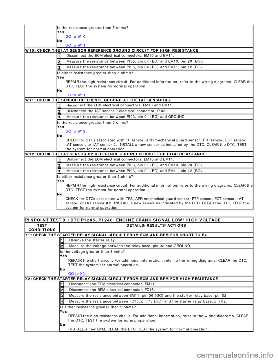
Is the res
istance greater than 5 ohms?
Yes GO to W10
.
No
GO to W11
.
W10 :
CHECK THE IAT SENSOR REFERENCE
GROUND CIRCUIT FOR HIGH RESISTANCE
Di
sconnect the ECM electrical connectors, EM10 and EM11.
1
Meas
ure t
he resistance between PI35,
pin 04 (BG) and EM10, pin 20 (BG).
2
Measure t
he resistance between PI35,
pin 04 (BG) and EM11, pin 12 (BG).
3
Is either resistance greater
than 5 ohms?
Yes REPAIR the high resistance circuit. For additional information, refer to the wiring diagrams. CLEAR the
DTC. TEST the system for normal operation.
No GO to W11
.
W11 :
CHECK THE SENSOR REFERENCE GROUND AT THE IAT SENSOR #2
Re
conn
ect the ECM electrical connectors, EM10 and EM11.
1
Di
sc
onnect the IAT sensor 2 electrical connector, PI03.
2
Meas
ure t
he resistance between PI03, pin 01 (BG) and GROUND.
3
Is th
e res
istance greater than 5 ohms?
Yes GO to W12
.
No
CHECK
for DTCs associated with TP sensor, APP/
mechanical guard sensor, FTP sensor, ECT sensor,
IAT sensor, or IAT sensor 2. INST ALL a new sensor as indicated by the DTC. CLEAR the DTC. TEST
the system for normal operation.
W12 :
CHECK THE IAT SENSOR #2 REFERENC
E GROUND CIRCUIT FOR HIGH RESISTANCE
Di
sconnect the ECM electrical connectors, EM10 and EM11.
1
Meas
ure t
he resistance between PI03,
pin 01 (BG) and EM10, pin 20 (BG).
2
Measure t
he resistance between PI03,
pin 01 (BG) and EM11, pin 12 (BG).
3
Is either resistance greater
than 5 ohms?
Yes REPAIR the high resistance circuit. For additional information, refer to the wiring diagrams. CLEAR the
DTC. TEST the system for normal operation.
No CHECK for DTCs associated with TPS, APP/mechanical guard sensor, FTP sensor, ECT sensor, IAT
sensor, or IAT sensor #2. INSTALL a new sensor as indicated by the DTC. CLEAR the DTC. TEST the
system for normal operation.
PINPO
INT TEST X : DTC P1245, P1246; ENGINE CRANK SIGNAL LOW/HIGH VOLTAGE
TE
S
T
CONDITIONS
D E
TAILS/RESULTS/ACTIONS
X
1
: CHECK THE STARTER RELAY SIGNAL CIRC
UIT FROM ECM AND BPM FOR SHORT TO B+
Re
move the starter relay.
1
Meas
ure t
he voltage between the
relay base, pin 02 and GROUND.
2
Is the volt
age greater than 3 volts?
Yes REPAIR the short circuit. For addi tional information, refer to the wiring diagrams. CLEAR the DTC.
TEST the system for normal operation.
No GO to X2
.
X2
: CHECK THE STARTER RELAY SIGNAL CIRCUI
T FROM ECM AND BPM FOR HIGH RESISTANCE
Di
sconnect the ECM electrical connector, EM11.
1
Disc
onne
ct the BPM electrical connector, FC15.
2
Meas
ure t
he resistance between EM11, pin 06
(GO) and the starter relay base, pin 02.
3
Measure t
he resistance between FC15, pin 73
(GO) and the starter relay base, pin 02.
4
Is either resistance greater
than 5 ohms?
Yes REPAIR the high resistance circui t. For additional information, refer to the wiring diagrams. CLEAR
the DTC. TEST the system for normal operation.
No INSTALL a new BPM. CLEAR the DTC. TEST the system for normal operation.
Page 1975 of 2490

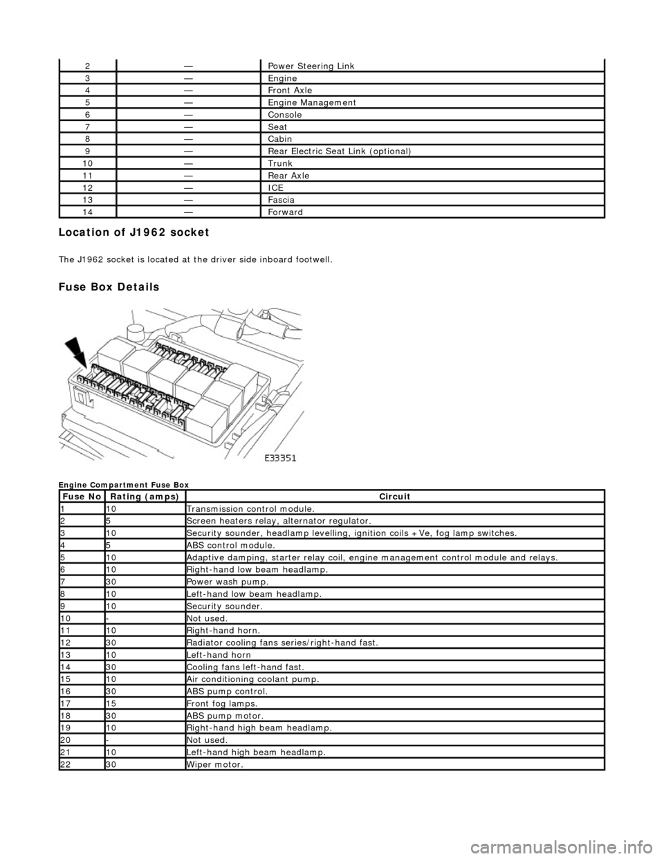
Location of J1962 socket
The J1962 socket is located at the driver side inboard footwell.
Fuse Box Details
Engine Compartment Fuse Box
2—Power Steering Link
3—Engine
4—Front Axle
5—Engine Management
6—Console
7—Seat
8—Cabin
9—Rear Electric Seat Link (optional)
10—Trunk
11—Rear Axle
12—ICE
13—Fascia
14—Forward
Fuse NoRating (amps)Circuit
110Transmission control module.
25Screen heaters relay, alternator regulator.
310Security sounder, headlamp levelling, ignition coils +Ve, fog lamp switches.
45ABS control module.
510Adaptive damping, starter relay coil, engine management control module and relays.
610Right-hand low beam headlamp.
730Power wash pump.
810Left-hand low beam headlamp.
910Security sounder.
10-Not used.
1110Right-hand horn.
1230Radiator cooling fans series/right-hand fast.
1310Left-hand horn
1430Cooling fans left-hand fast.
1510Air conditioning coolant pump.
1630ABS pump control.
1715Front fog lamps.
1830ABS pump motor.
1910Right-hand high beam headlamp.
20-Not used.
2110Left-hand high beam headlamp.
2230Wiper motor.
Page 1976 of 2490

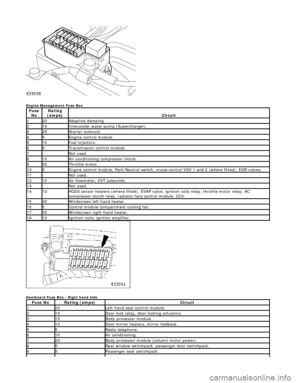
Engine Management Fuse Box
Heelboard Fuse Box - Right hand side
Fuse NoRating
(amps)Circuit
120Adaptive damping
215Intercooler water pump (Supercharger)
325Starter solenoid.
45Engine control module.
510Fuel injectors.
65Transmission control module
7-Not used.
810Air conditioning compressor clutch.
930Throttle motor.
105Engine control module, Park/Neutr al switch, cruise control VSV 1 and 2 (where fitted), EGR valves.
11-Not used.
1210Air flowmeter, VVT solenoids.
13-Not used.
1410HO2S sensor heaters (where fitted ), EVAP valve, ignition coils relay, throttle motor relay, AC
compressor clutch relay, radi ator fans control module, CCV.
1530Windscreen left-hand heater.
165Control module compartment cooling fan.
1730Windscreen right-hand heater.
1810Ignition coils, ignition amplifier.
Fuse NoRating (amps)Circuit
120Left-hand seat control module.
215Door lock relay, door locking actuators.
315Body processor module.
410Door mirror heaters, mirror foldback.
55Radio telephone.
610Air conditioning.
720Body processor module (column motor power).
85Rear window switchpack, passenger door switchpack.
95Passenger seat switchpack.
Page 1979 of 2490

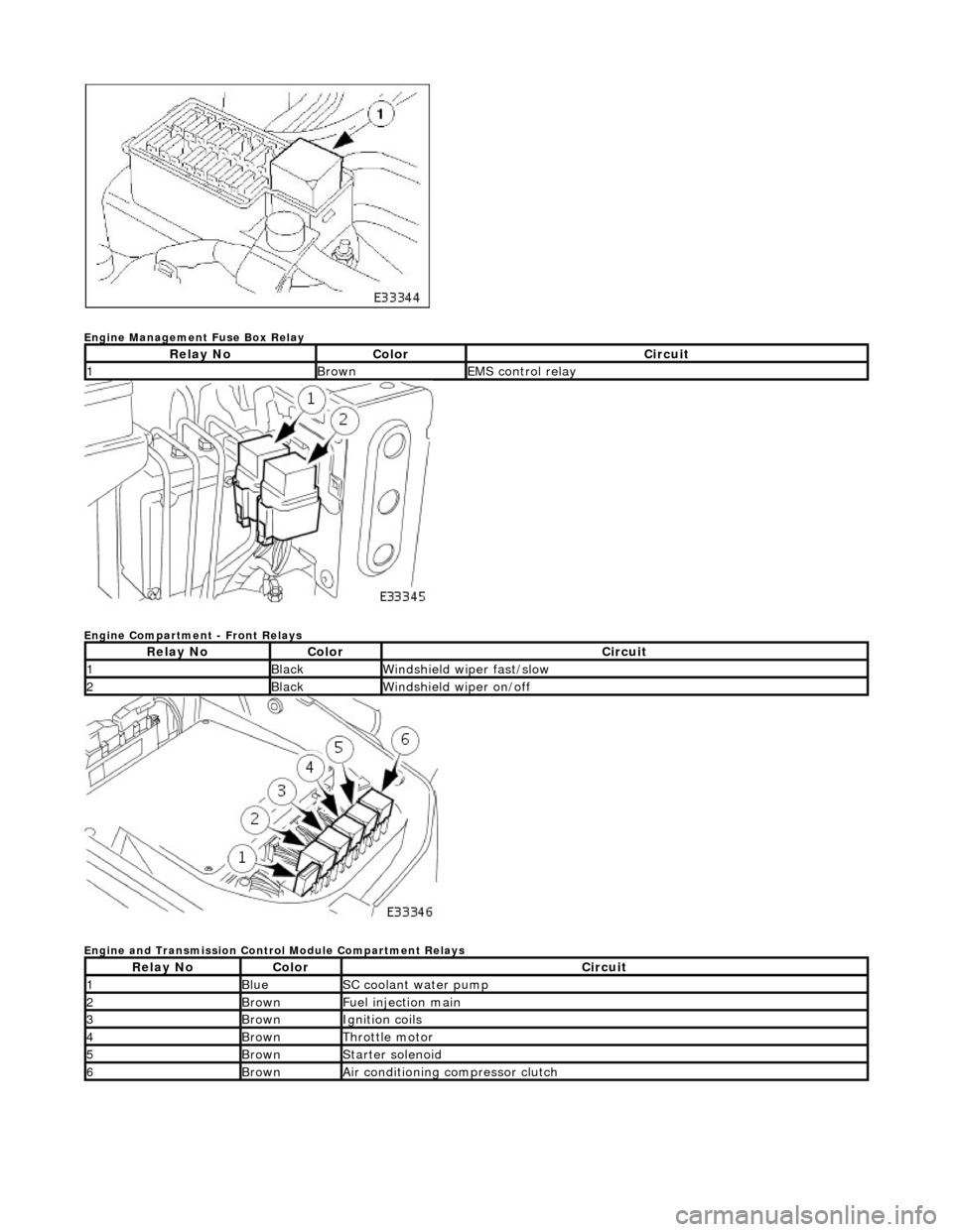
Engine Management Fuse Box Relay
Engine Compartment - Front Relays
Engine and Transmission Control Module Compartment Relays
Relay NoColorCircuit
1BrownEMS control relay
Relay NoColorCircuit
1BlackWindshield wiper fast/slow
2BlackWindshield wiper on/off
Relay NoColorCircuit
1BlueSC coolant water pump
2BrownFuel injection main
3BrownIgnition coils
4BrownThrottle motor
5BrownStarter solenoid
6BrownAir conditioning compressor clutch