fuel injector connector JAGUAR X308 1998 2.G Workshop Manual
[x] Cancel search | Manufacturer: JAGUAR, Model Year: 1998, Model line: X308, Model: JAGUAR X308 1998 2.GPages: 2490, PDF Size: 69.81 MB
Page 708 of 2490
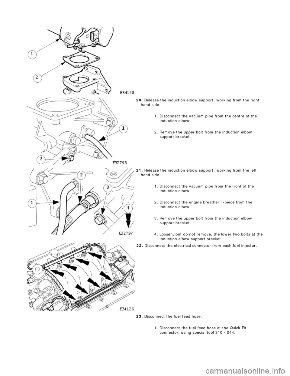
20. Release the induction elbow su pport; working from the right
hand side.
1. Disconnect the vacuum pi pe from the centre of the
induction elbow.
2. Remove the upper bolt from the induction elbow support bracket.
21. Release the induction elbow su pport; working from the left
hand side.
1. Disconnect the vacuum pipe from the front of the
induction elbow.
2. Disconnect the engine breather T-piece from the induction elbow.
3. Remove the upper bolt from the induction elbow support bracket.
4. Loosen, but do not remove , the lower two bolts at the
induction elbow support bracket.
22. Disconnect the electrical conne ctor from each fuel injector.
23. Disconnect the fuel feed hose.
1. Disconnect the fuel f eed hose at the Quick Fit
connector, using special tool 310 - 044.
Page 714 of 2490
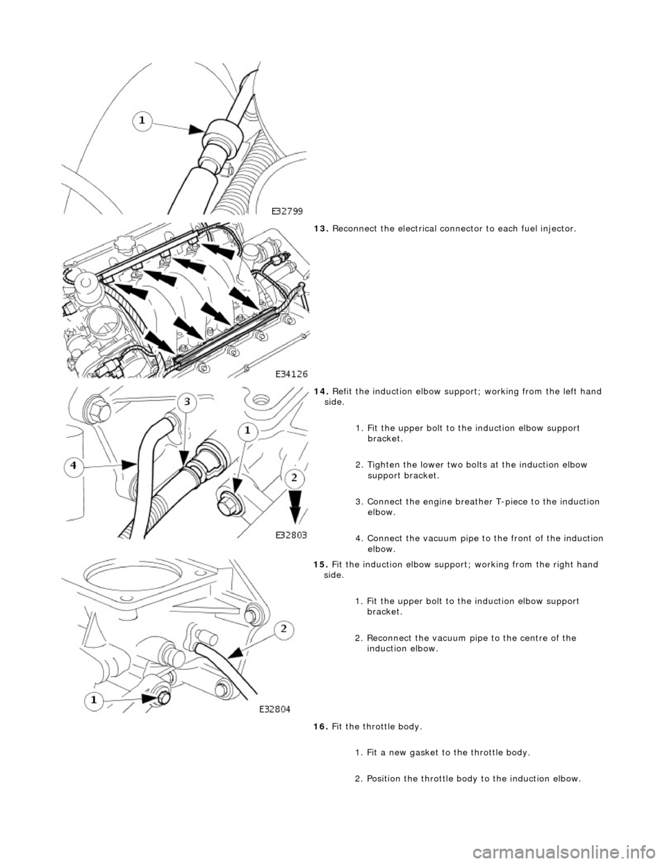
13. Reconnect the electrical connector to each fuel injector.
14. Refit the induction elbow support ; working from the left hand
side.
1. Fit the upper bolt to the induction elbow support
bracket.
2. Tighten the lower two bolts at the induction elbow support bracket.
3. Connect the engine breather T-piece to the induction elbow.
4. Connect the vacuum pipe to the front of the induction
elbow.
15. Fit the induction elbow support; working from the right hand
side.
1. Fit the upper bolt to the induction elbow support
bracket.
2. Reconnect the vacuum pi pe to the centre of the
induction elbow.
16. Fit the throttle body.
1. Fit a new gasket to the throttle body.
2. Position the throttle body to the induction elbow.
Page 722 of 2490
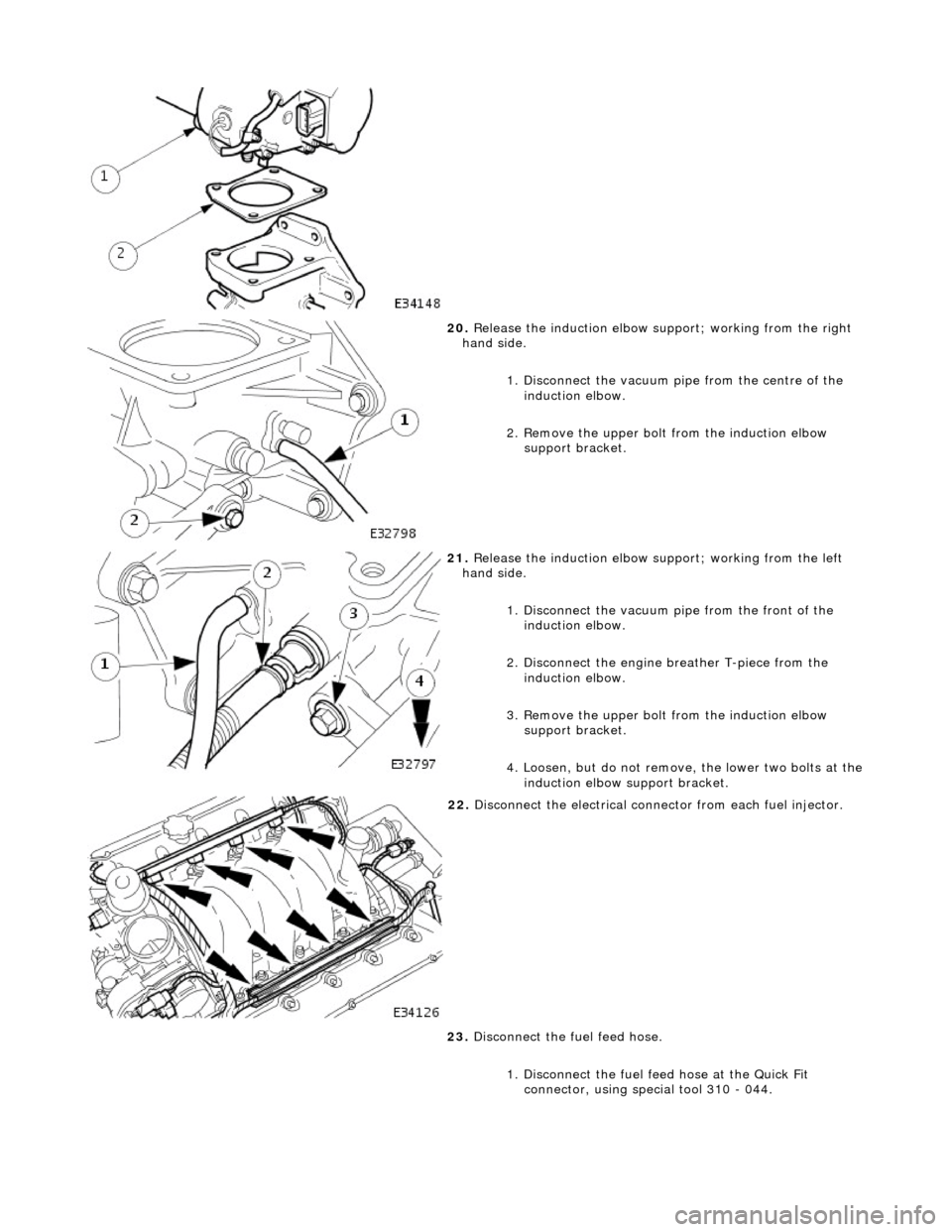
20. Release the induction elbow su pport; working from the right
hand side.
1. Disconnect the vacuum pi pe from the centre of the
induction elbow.
2. Remove the upper bolt from the induction elbow support bracket.
21. Release the induction elbow su pport; working from the left
hand side.
1. Disconnect the vacuum pipe from the front of the
induction elbow.
2. Disconnect the engine breather T-piece from the induction elbow.
3. Remove the upper bolt from the induction elbow support bracket.
4. Loosen, but do not remove , the lower two bolts at the
induction elbow support bracket.
22. Disconnect the electrical conne ctor from each fuel injector.
23. Disconnect the fuel feed hose.
1. Disconnect the fuel f eed hose at the Quick Fit
connector, using special tool 310 - 044.
Page 724 of 2490
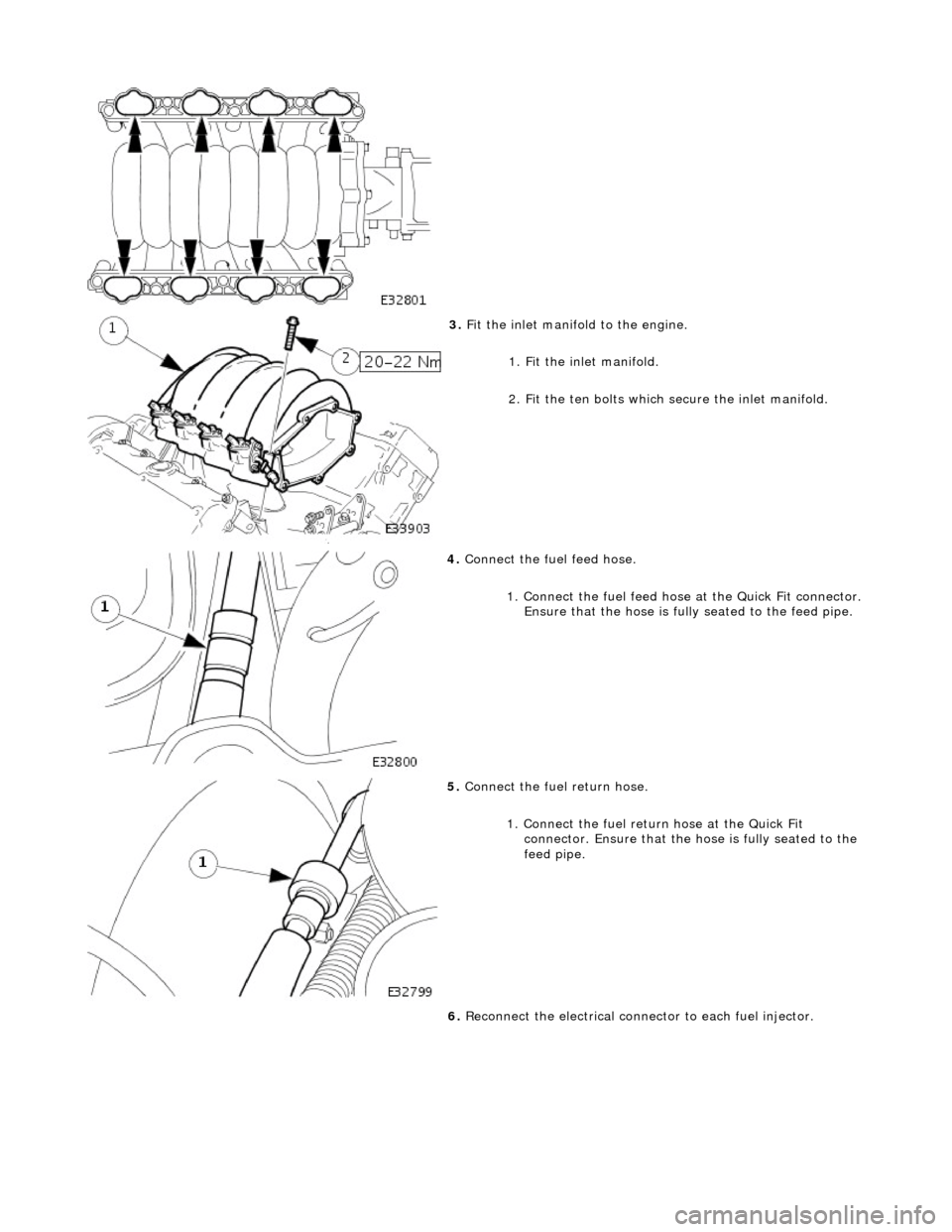
3. Fit the inlet manifold to the engine.
1. Fit the inlet manifold.
2. Fit the ten bolts which secure the inlet manifold.
4. Connect the fuel feed hose.
1. Connect the fuel feed hose at the Quick Fit connector. Ensure that the hose is fully seated to the feed pipe.
5. Connect the fuel return hose.
1. Connect the fuel return hose at the Quick Fit
connector. Ensure th at the hose is fully seated to the
feed pipe.
6. Reconnect the electrical connector to each fuel injector.
Page 934 of 2490
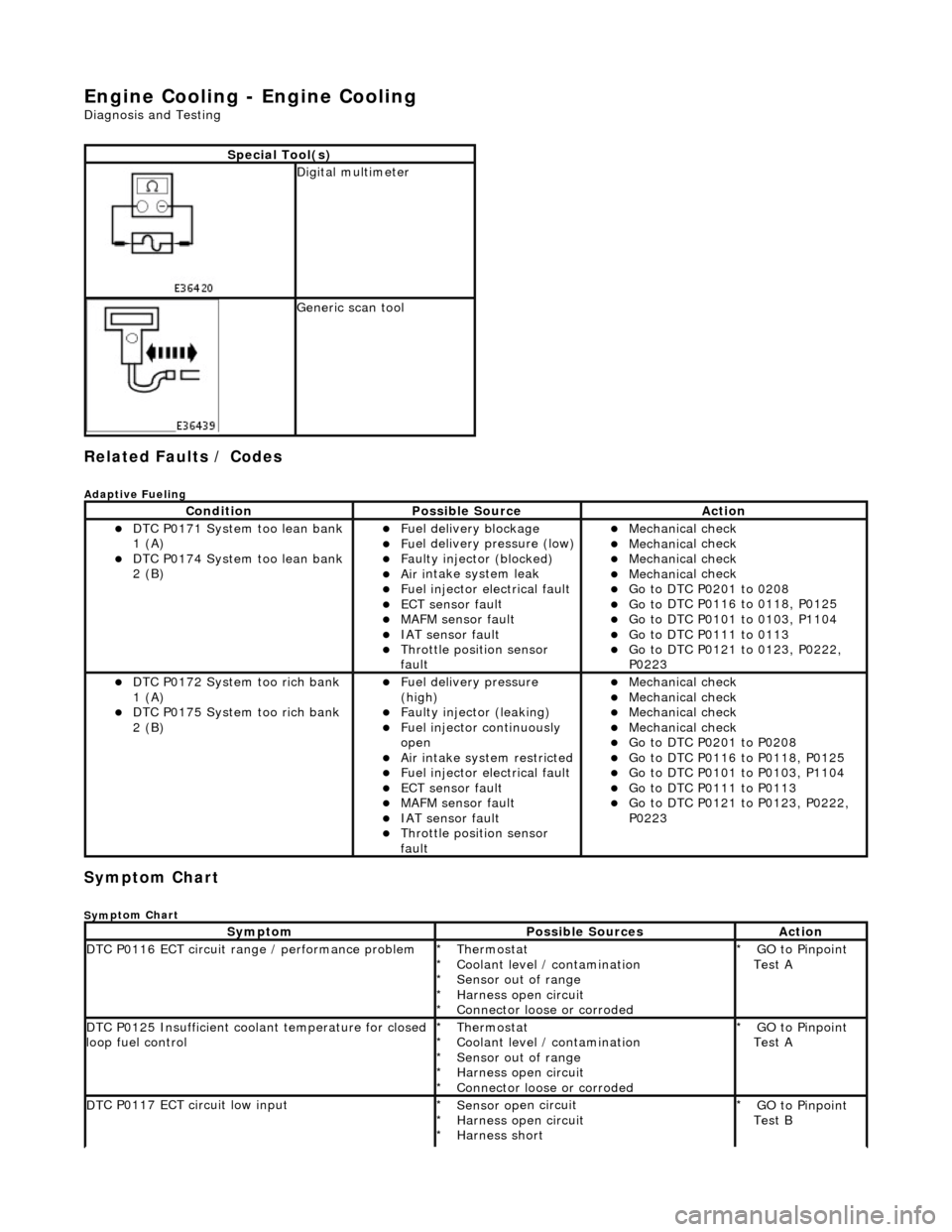
Engine Cooling - Engine Cooling
Diagn
osis and Testing
Related Faults / Codes
Adaptive
Fue
ling
Sym
p
tom Chart
Sy
m
ptom Chart
S
p
ecial Tool(s)
D
i
gital multimeter
Generi
c scan tool
Conditi
on
Possib
l
e Source
Acti
o
n
D
T
C P0171 System too lean bank
1 (A)
D T
C P0174 System too lean bank
2 (B)
Fuel delivery blockage Fu
el delivery pressure (low)
F
a
ulty injector (blocked)
Ai
r i
ntake system leak
F
u
el injector electrical fault
ECT sensor
faul
t
MAFM sensor fault IAT se
nsor fault
Thro
tt
le position sensor
fault
Mec hanica
l check
Mec
hanica
l check
Mec
hanica
l check
Mec
hanica
l check
Go t
o DTC P020
1 to 0208
Go t
o
DTC P0116 to 0118, P0125
Go t
o
DTC P0101 to 0103, P1104
Go t
o DTC P011
1 to 0113
Go t
o
DTC P0121 to 0123, P0222,
P0223
D T
C P0172 System too rich bank
1 (A)
D T
C P0175 System too rich bank
2 (B)
F u
el delivery pressure
(high)
F a
ulty injector (leaking)
F
u
el injector continuously
open
Ai r i
ntake system restricted
Fu
el injector electrical fault
ECT sensor
faul
t
MAFM sensor fault IAT sensor fault
Thrott
le position sensor
fault
Mec hanica
l check
Mec
hanica
l check
Mec
hanica
l check
Mec
hanica
l check
Go t
o DTC P020
1 to P0208
Go t
o
DTC P0116 to P0118, P0125
Go t
o
DTC P0101 to P0103, P1104
Go t
o DTC P011
1 to P0113
Go t
o
DTC P0121 to P0123, P0222,
P0223
Sy m
ptom
Possib
l
e Sources
Acti
o
n
D
T
C P0116 ECT circuit range / performance problem
Thermostat
Coo
l
ant level / contamination
Sensor out of range
Harness open circuit
Connector loose or corroded
*
*
*
*
*
GO to Pinpoint
Test A
*
D
T
C P0125 Insufficient coolant temperature for closed
loop fuel control
Thermostat
Coo l
ant level / contamination
Sensor out of range
Harness open circuit
Connector loose or corroded
*
*
*
*
*
GO to Pinpoint
Test A
*
D
T
C P0117 ECT circuit low input
Sensor o
p
en circuit
Harness open circuit
Harness short
*
*
*
GO to Pinpoint
Test B
*
Page 1021 of 2490
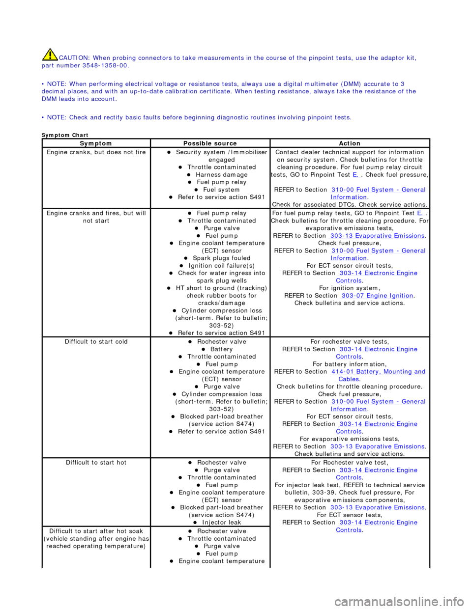
CAUTI
ON: When probing connectors to take
measurements in the course of the pinpoint tests, use the adaptor kit,
part number 3548-1358-00.
• NOTE: When performing electrical voltag e or resistance tests, always use a digital multimeter (DMM) accurate to 3
decimal places, and with an up-t o-date calibration certificate. When testing resistance, always take the resistance of the
DMM leads into account.
• NOTE: Check and rectify basic faults before beginning diagnostic ro utines involving pinpoint tests.
Sy
mptom Chart
Sy
mptom
Possib
le source
Acti
on
Engine
cranks, but does not fire
Secu
rity system /Immobiliser
engaged
Thr
ottle contaminated
Harness damage
F
uel pump relay
Fue
l system
R
efer to service action S491
Contact dealer techn
ical
support for information
on security system. Chec k bulletins for throttle
cleaning procedure. For fuel pump relay circuit
tests, GO to Pinpoint Test E.
.
Check fuel pressure,
REFER to Section 310
-00
Fuel System
- Gen
eral
Informati
on
.
Chec
k for associated DTCs
. Check service actions.
Engine
cranks and fires, but will
not start
F
uel pump relay
Thr
ottle contaminated
Purge
valve
Fue
l pump
Engine coolan
t temperature
(ECT) sensor
Spark plugs
fouled
Ignition coil
failure(s)
Check f
or water ingress into
spark plug wells
HT sho
rt to ground (tracking)
check rubber boots for cracks/damage
Cyl
inder compression loss
(short-term. Refer to bulletin;
303-52)
R
efer to service action S491
F
or fuel pump relay tests,
GO to Pinpoint Test E.
.
Check bull
etins for throttle cleaning procedure. For
evaporative emissions tests,
REFER to Section 303
-1
3 Evaporative Emissions
. Chec
k fuel pressure,
REFER to Section 310
-00
Fuel System
- Ge
neral
Informati
on
.
F
or ECT sensor circuit tests,
REFER to Section 303
-14 Elec
tronic Engine
Controls.
For ign
ition system,
REFER to Section 303
-07
Engine Ignition
.
Check bulletins an d service
actions.
D
ifficult to start cold
Roc
hester valve
Batt
ery
Thr
ottle contaminated
Fue
l pump
Engine coolan
t temperature
(ECT) sensor
Purge
valve
Cyl
inder compression loss
(short-term. Refer to bulletin;
303-52)
Blocked part-load breather (
service action S474)
R
efer to service action S491
F
or rochester valve tests,
REFER to Section 303
-14 Elec
tronic Engine
Controls.
F
or battery information,
REFER to Section 414
-0
1 Battery, Mounting and
Cables.
Check bull
etins for throttle cleaning procedure.
Check fuel pressure,
REFER to Section 310
-00
Fuel System
- Ge
neral
Informati
on
.
F
or ECT sensor circuit tests,
REFER to Section 303
-14 Elec
tronic Engine
Controls.
For evaporat
ive emissions tests,
REFER to Section 303
-1
3 Evaporative Emissions
. Check bulletins an
d
service actions.
D
ifficult to start hot
Roc
hester valve
Purge
valve
Thr
ottle contaminated
Fue
l pump
Engine coolan
t temperature
(ECT) sensor
Blocked part-load breather (
service action S474)
Injec
tor leak
F
or Rochester
valve test,
REFER to Section 303
-14 Elec
tronic Engine
Controls.
Fo
r injector leak test, REFER to technical service
bulletin, 303-39. Check fuel pressure, For evaporative emissions components,
REFER to Section 303
-1
3 Evaporative Emissions
. F
or ECT sensor tests,
REFER to Section 303
-14 Elec
tronic Engine
Controls. D
ifficult to start after hot soak
(vehicle standing after engine has
reached operating temperature)
Roc
hester valve
Thr
ottle contaminated
Purge
valve
Fue
l pump
Engine coolan
t temperature
Page 1028 of 2490
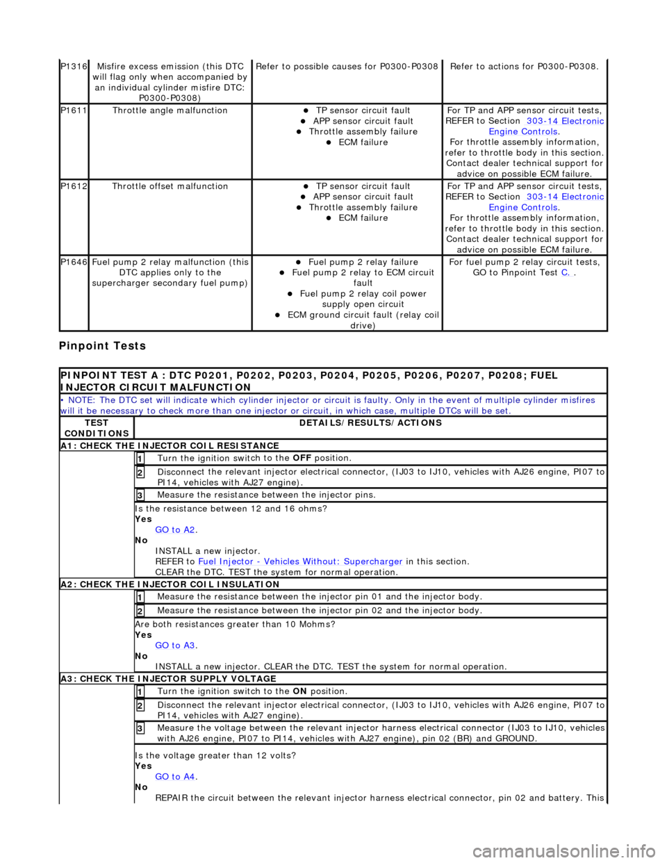
Pinpoint Tests
P1316Mi
sfire excess emission (this DTC
will flag only when accompanied by an individual cylinder misfire DTC: P0300-P0308)
Re
fer to possible causes for P0300-P0308
R
e
fer to actions for P0300-P0308.
P1611Thr
o
ttle angle malfunction
TP sensor
ci
rcuit fault
APP sensor circuit faul
t Throttle
assembly failure
ECM failu
r
e
F
or TP and APP
sens
or circuit tests,
REFER to Section 303
-14 El
ectronic
Engine
C
ontrols
.
F o
r throttle assembly information,
refer to throttle body in this section.
Contact dealer technical support for advice on possible ECM failure.
P1612Throttl e
offset malfunction
TP sensor
ci
rcuit fault
APP sensor circuit faul
t Throttle
assembly failure
ECM failu
r
e
F
or TP and APP
sens
or circuit tests,
REFER to Section 303
-14 El
ectronic
Engine
C
ontrols
.
F o
r throttle assembly information,
refer to throttle body in this section.
Contact dealer technical support for advice on possible ECM failure.
P1646Fu
el pump 2 relay malfunction (this
DTC applies only to the
supercharger secondary fuel pump)
Fu
el pump 2 relay failure
Fu
el pump 2 relay to ECM circuit
fault
Fu
el pump 2 relay coil power
supply open circuit
ECM ground circuit faul t (relay coil
drive)
For fuel pump 2 r
elay circuit tests,
GO to Pinpoint Test C.
.
PI
NPOINT TEST A : DTC P0201, P0202, P0203, P0204, P0205, P0206, P0207, P0208; FUEL
INJECTOR CIRCUIT MALFUNCTION
• NOTE
: The DTC set will indicate which cylinder injector or circ
uit is faulty. Only in the event of multiple cylinder misfires
will it be necessary to chec k more than one injector or circuit, in which case, multiple DTCs will be set.
TES
T
CONDITIONS
D E
TAILS/RESULTS/ACTIONS
A1
: CH
ECK THE INJECTOR COIL RESISTANCE
Turn the ignition swi
t
ch to the OFF
position.
1
Disconne
ct the relevant injector electrical connector
, (IJ03 to IJ10, vehicles with AJ26 engine, PI07 to
PI14, vehicles with AJ27 engine).
2
Meas ure t
he resistance between the injector pins.
3
Is
t
he resistance between 12 and 16 ohms?
Yes GO to A2
.
No
INST
ALL a new injector.
REFER to Fuel Injector
- Ve hicles With
out: Supercharger
in this
section.
CLEAR the DTC. TEST the system for normal operation.
A2: CHECK
THE INJECTOR COIL INSULATION
Meas
ure t
he resistance between the inje
ctor pin 01 and the injector body.
1
Measure t
he resistance between the inje
ctor pin 02 and the injector body.
2
Are both re
sistances greater than 10 Mohms?
Yes GO to A3
.
No
INST
ALL a new injector. CLEAR the DTC. TE
ST the system for normal operation.
A3: CHECK THE INJECTOR
SUPPLY VOLTAGE
Turn the ignition swi
t
ch to the ON
position.
1
Disconne
ct the relevant injector electrical connector
, (IJ03 to IJ10, vehicles with AJ26 engine, PI07 to
PI14, vehicles with AJ27 engine).
2
Meas ure t
he voltage between the relevant injector harness electrical connector (IJ03 to IJ10, vehicles
with AJ26 engine, PI07 to PI 14, vehicles with AJ27 engine), pin 02 (BR) and GROUND.
3
Is the volt
age greater than 12 volts?
Yes GO to A4
.
No
R
EPAIR the circuit between the relevant injector harn
ess electrical connector, pin 02 and battery. This
Page 1029 of 2490
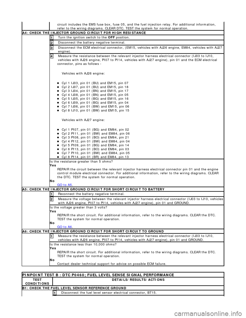
ci
rcuit includes the EMS fuse box,
fuse 05, and the fuel injection relay. For additional information,
refer to the wiring diagrams. CLEAR DTC. TEST the system for normal operation.
A4: CHECK
THE INJECTOR GROUND
CIRCUIT FOR HIGH RESISTANCE
Turn the ignition swi
tch to the OFF
position.
1
Di
sconnect the battery negative terminal.
2
D
isconnect the ECM electrical connector, (EM15, vehi
cles with AJ26 engine, EM84, vehicles with AJ27
engine).
3
Meas
ure the resistance between the relevant injector harness electrical connector (IJ03 to IJ10,
vehicles with AJ26 engine, PI07 to PI14, vehicles with AJ27 engine), pin 01 and the ECM electrical
connector, pins as follows -
Vehicles with AJ26 engine:
Cy
l 1 IJ03, pin 01 (BU) and EM15, pin 07
Cy
l 2 IJ07, pin 01 (BU) and EM15, pin 18
Cy
l 3 IJ04, pin 01 (BN) and EM15, pin 17
Cy
l 4 IJ08, pin 01 (BN) and EM15, pin 05
Cy
l 5 IJ05, pin 01 (BG) and EM15, pin 16
Cy
l 6 IJ09, pin 01 (BG) and EM15, pin 04
Cy
l 7 IJ06, pin 01 (BW) and EM15, pin 06
Cy
l 8 IJ10, pin 01 (BW) and EM15, pin 15
Vehicles with AJ27 engine:
Cy
l 1 PI07, pin 01 (B
G) and EM84, pin 02
Cy
l 2 PI11, pin 01 (BW) and EM84, pin 06
Cy
l 3 PI08, pin 01 (BO) and EM84, pin 21
Cy
l 4 PI12, pin 01 (BW) and EM84, pin 04
Cy
l 5 PI09, pin 01 (B
G) and EM84, pin 14
Cy
l 6 PI13, pin 01 (BO) and EM84, pin 03
Cy
l 7 PI10, pin 01 (BW) and EM84, pin 05
Cy
l 8 PI14, pin 01 (BR) and EM84, pin 13
4
Is th
e resistance greater than 5 ohms?
Yes REPAIR the circuit between the relevant injector harness electrical connector pin 01 and the engine
control module electrical connecto r. For additional information, refer to the wiring diagrams. CLEAR
the DTC. TEST the system for normal operation.
No GO to A5
.
A5: CHECK
THE INJECTOR GROUND CI
RCUIT FOR SHORT CIRCUIT TO BATTERY
R
econnect the battery negative terminal.
1
Meas
ure the voltage between the relevant injector harness electrical connector (IJ03 to IJ10, vehicles
with AJ26 engine, PI07 to PI14, vehicles with AJ27 engine), pin 01 and GROUND.
2
Is th
e voltage greater than 3 volts?
Yes REPAIR the short circuit. For addi tional information, refer to the wiring diagrams. CLEAR the DTC.
TEST the system for normal operation.
No GO to A6
.
A6: CHECK
THE INJECTOR GROUND CI
RCUIT FOR SHORT CIRCUIT TO GROUND
Meas
ure the resistance between the relevant injector harness electrical connector (IJ03 to IJ10,
vehicles with AJ26 engine, PI07 to PI14, vehicles with AJ27 engine), pin 01 and GROUND.
1
Is
the resistance less than 10,000 ohms?
Yes REPAIR the short circuit. For addi tional information, refer to the wiring diagrams. CLEAR the DTC.
TEST the system for normal operation.
No Contact dealer technical support for advice on possible ECM failure.
P
INPOINT TEST B : DTC P0460; FUEL
LEVEL SENSE SIGNAL PERFORMANCE
TE
ST
CONDITIONS
D
ETAILS/RESULTS/ACTIONS
B1: CHECK
THE FUEL LEVEL SENSOR REFERENCE GROUND
Di
sconnect the fuel level sensor electrical connector, BT15.
1
Page 1037 of 2490
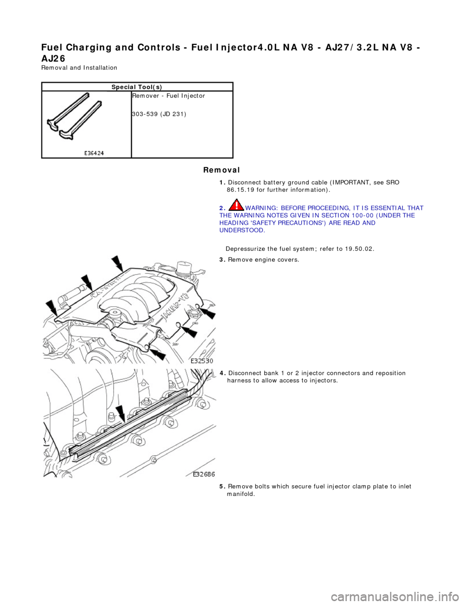
Fuel Ch
arging and Controls
- Fuel Injector4.0L NA V8 - AJ27/3.2L NA V8 -
AJ26
Re
moval and Installation
Remov
al
S
pecial Tool(s)
R
emover - Fuel Injector
303-539 (JD 231)
1. Disconnect battery ground cable (IMPORTANT, see SRO
86.15.19 for further information).
2. WARNING: BEFORE PROCEEDING, IT IS ESSENTIAL THAT
THE WARNING NOTES GIVEN IN SECTION 100-00 (UNDER THE
HEADING 'SAFETY PRECAUTIONS') ARE READ AND
UNDERSTOOD.
Depressurize the fuel sy stem; refer to 19.50.02.
3. R
emove engine covers.
4. Di
sconnect bank 1 or 2 inject
or connectors and reposition
harness to allow access to injectors.
5. Remove bolts which secure fuel injector clamp plate to inlet
manifold.
Page 1039 of 2490
Fuel Charging and Controls
- Fuel Injector4.0L SC V8 - AJ26
Rem
oval and Installation
Remov
al
Installation
1.
Disconnect battery ground cabl e (IMPORTANT, see SRO 86.15.19
for further information).
2. WARNING: BEFORE PROCEEDING, IT IS ESSENTIAL THAT
THE WARNING NOTES GIVEN IN SECTION 100-00 (UNDER THE
HEADING 'SAFETY PRECAUTIONS') ARE READ AND UNDERSTOOD.
Depressurize fuel system; refer to 19.50.02.
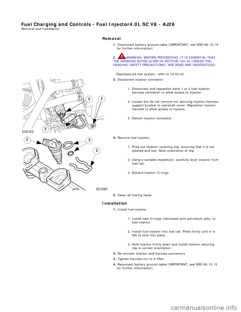
3.
Disconnect injector connector.
1. Disconnect and reposition bank 1 or 2 fuel injector harness connector to allow access to injector.
2. Loosen but do not remove nut securing injector harness support bracket to camshaft cover. Reposition injector
harness to allow access to injector.
3. Detach injector connector.
4.
Remove fuel injector.
1. Prise out injector retaining clip, ensuring that it is not ejected and lost. Note orientation of clip.
2. Using a suitable implement, carefully lever injector from
fuel rail.
3. Discard injector O-rings.
5. Clean all mating faces.
1. Install fuel injector.
1. Install new O-rings, lubricat ed with petroleum jelly, to
fuel injector.
2. Install fuel injector into fuel rail. Press firmly until it is felt to click into place.
3. Hold injector firmly down and install injector securing clip in correct orientation.
2. Re-connect injector and harness connectors.
3. Tighten harness nut to 4-5Nm.
4. Reconnect battery ground cable (IMPORTANT, see SRO 86.15.15
for further information).