generator JAGUAR X308 1998 2.G Workshop Manual
[x] Cancel search | Manufacturer: JAGUAR, Model Year: 1998, Model line: X308, Model: JAGUAR X308 1998 2.GPages: 2490, PDF Size: 69.81 MB
Page 24 of 2490

В
В В В В В В В В В В В В В
В В В В В В В В В 414‐02: В Generator В and В Regulator В
В В В В В В В В В В В В В В В В Descriptio nВ and В Operati
on
В
В В В В В В В В В В В В В В В В В В В В GeneratorВ
В В В В В В В В В В В В В В В В Diagnosis В and В Testing В
В В В В В В В В В В В В В В В В В В В В GeneratorВ
В В В В В В В В В В В В В В В В RemovalВ and В Installation В
В В В В В В В В В В В В В В В В В В В В GeneratorВ (86.10.02)  ‐ 3.2L В NA В V8  ‐ AJ26/4.0L В NA В V8  ‐ AJ27 В
В В В В В В В В В В В В В В В В В В В В GeneratorВ (86.10.02)  ‐ 4.0L В SCВ V8 ‐ AJ26 В
В В В В В В В В В В В В В В В В В В В В VoltageВ Regulator В (86.10.28) В
В
В В В В В В В В 415: В Information В and В Entertainment В Systems В
В
В В В В В В В В В В В В 415‐01: В Audio В Unit В
В В В В В В В В В В В В В В В В Description В and В Operati
onВ
В В В В В В В В В В В В В В В В В В В В AudioВ System В
В В В В В В В В В В В В В В В В Diagnosis В and В Testing В
В В В В В В В В В В В В В В В В В В В В AudioВ System В
В В В В В В В В В В В В В В В В RemovalВ and В Installation В
В В В В В В В В В В В В В В В В В В В В CapacitorВ (86.10.33) В
В
В В В В В В В В В В В В 415‐02: В Antenna В
В В В В В В В В В В В В В В В В Description В and В Operation В
В В В В В В В В В В В В В В В В В В В В AntennaВ
В В В В В В В В В В В В В В В В Diagnosis В and В Testing В
В В В В В В В В В В В В В В В В В В В В AntennaВ
В
В В В В В В В В В В В В 415‐03: В Speakers В
В В В В В В В В В В В В В В В В Description В and В Operation В
В В В В В В В В В В В В В В В В В В В В SpeakersВ
В В В В В В В В В В В В В В В В Diagnosis В and В Testing В
В В В В В В В В В В В В В В В В В В В В SpeakersВ
В В В В В В В В В В В В В В В В RemovalВ and В Installation В
                    A‐Pillar T
weeter В Speaker В LH В
В В В В В В В В В В В В В В В В В В В В A‐PillarВ Tweeter В Speaker В RH В (86.50.65) В
В В В В В В В В В В В В В В В В В В В В DoorВ Speaker В (86.50.13) В
Page 48 of 2490
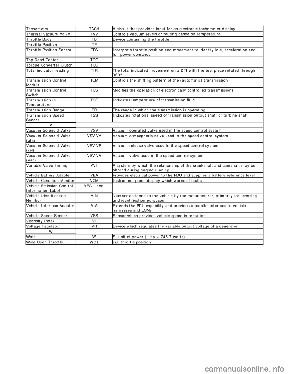
Tacho
meter
TACHA
ci
rcuit that provides input for
an electronic tachometer display
Thermal Vacuu
m Valve
TVVControls vacuum l
e
vels or
routing based on temperature
Throttle
Body
TBDe
vi
ce containing the throttle
Throttl
e
Position
TP
Throttl
e
Position Sensor
TPSInterprets throttl
e
position and movement to iden tify idle, acceleration and
full-power demands
Top Dead CenterTDC
Torque Converter C
lutch
TCC
To
tal
indicator reading
TIRThe t
o
tal indicated movement on a DTI with the test piece rotated through
360В°
Transm
ission Control
Module
TCMControls
the shifting pattern
of the (automatic) transmission
Transm
ission Control
Switch
TCSModifi es
the operation of electronically controlled transmissions
Transmission Oil
TemperatureTOTIndi
cat
es temperature of transmission fluid
Transmission RangeTRThe ran
g
e in which the transmission is operating
Transmission Spe
e
d
Sensor
TSSIndi cat
es rotational speed of transmission output shaft or turbine shaft
V
Vacuu
m
Solenoid Valve
VSVVacuu
m
operated valve used in the speed control system
Vacuu
m
Solenoid Valve
(atm)
VSV VAVacuu m
atmospheric valve used in the speed control system
Vacuu
m
Solenoid Valve
(rel)
VSV VRVacuu m
release valve used in the speed control system
Vacuu
m
Solenoid Valve
(vac)
VSV VVVacuu m
valve used in the speed control system
Variable Valve TimingVVTA
s
ystem by which the relationship of the crankshaft and camshaft may be
altered during engine running
Vehi cl
e Battery Adapter
VBAProvide
s
electrical power to the PDU
and supplies a battery reference level
Vehicl
e Condition Monitor
VCMInst
rum
ent panel display which warns of faults
Ve
hic
le Emission Control
Information Label
VECI Label
Vehi cl
e Identification
Number
VINN u
mber assigned to the vehicle by the manufacturer, primarily for licensing
and identification purposes
Vehi cl
e Interface Adapter
VIAExtends the
PDU ca
pability and provid
es a parallel interface to vehicle
harnesses and ECMs
Vehicle Spe e
d Sensor
VSSSens
or which provides ve
hicle speed information
Viscosity In
dexVI
Voltage RegulatorVRDe
vice which regulates the variable output voltage of a generator
W
Wat
tWSI unit of power (1 hp = 7
45.7 watts)
W
i
de Open Throttle
WO
TFu
ll throttle position
Page 67 of 2490
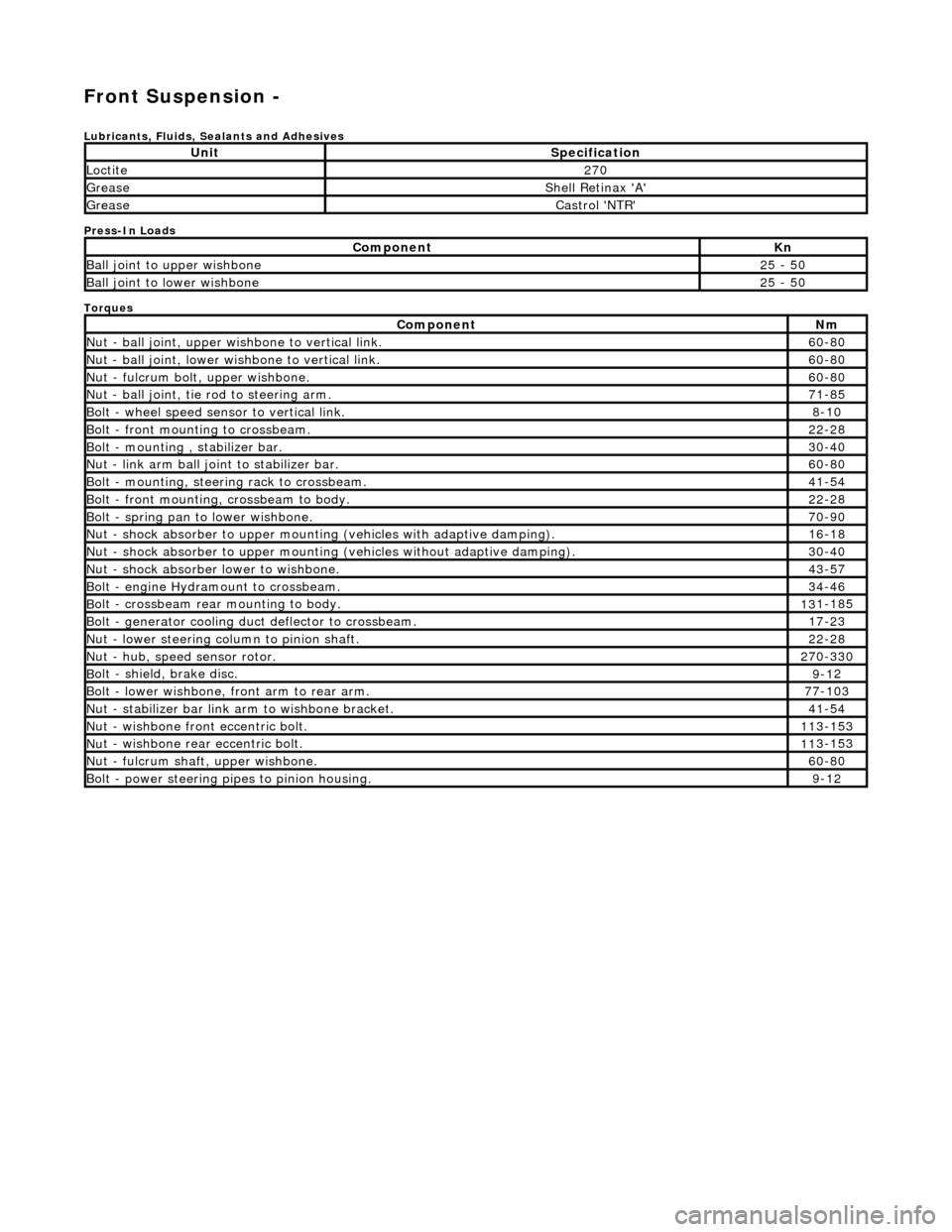
Front Suspension -
Lubri
cants, Fluids, Sealants and Adhesives
Press-In Loads
Torques
UnitS
pecification
Loctite27
0
Greas
e
Shell Retin
ax 'A'
Greas
e
Castro
l 'NTR'
Com
ponent
Kn
Ball join
t to upper wishbone
25
- 50
B
all joint to lower wishbone
25
- 50
Com
ponent
Nm
N
ut - ball joint, upper wishbone to vertical link.
60
-80
N
ut - ball joint, lower wishbone to vertical link.
60
-80
Nu
t - fulcrum bolt, upper wishbone.
60
-80
N
ut - ball joint, tie rod to steering arm.
71
-85
Bol
t - wheel speed sensor to vertical link.
8-1
0
Bol
t - front mounting to crossbeam.
22
-28
Bolt
- mounting , stabilizer bar.
30
-40
N
ut - link arm ball joint to stabilizer bar.
60
-80
Bolt
- mounting, steering rack to crossbeam.
41
-54
B
olt - front mounting, crossbeam to body.
22
-28
Bol
t - spring pan to lower wishbone.
70
-90
N
ut - shock absorber to upper mounting
(vehicles with adaptive damping).
16
-18
Nu
t - shock absorber to upper mounting (vehicles without adaptive damping).
30
-40
N
ut - shock absorber lower to wishbone.
43
-57
B
olt - engine Hydramount to crossbeam.
34
-46
B
olt - crossbeam rear mounting to body.
13
1-185
Bol
t - generator cooling du
ct deflector to crossbeam.
17
-23
N
ut - lower steering column to pinion shaft.
22
-28
N
ut - hub, speed sensor rotor.
27
0-330
B
olt - shield, brake disc.
9-1
2
Bol
t - lower wishbone, front arm to rear arm.
77
-103
Nu
t - stabilizer bar link arm to wishbone bracket.
41
-54
N
ut - wishbone front
eccentric bolt.
11
3-153
Nu
t - wishbone rear
eccentric bolt.
11
3-153
N
ut - fulcrum shaft, upper wishbone.
60
-80
Bolt -
power steering pi
pes to pinion housing.
9-1
2
Page 117 of 2490
Front Suspension - Fro
nt Stabilizer Bar
Re
moval and Installation
Materials
S
pecification
Cas
trol NTR
Remov
al
Na
me
R
ubber Suspension Insulator Lube
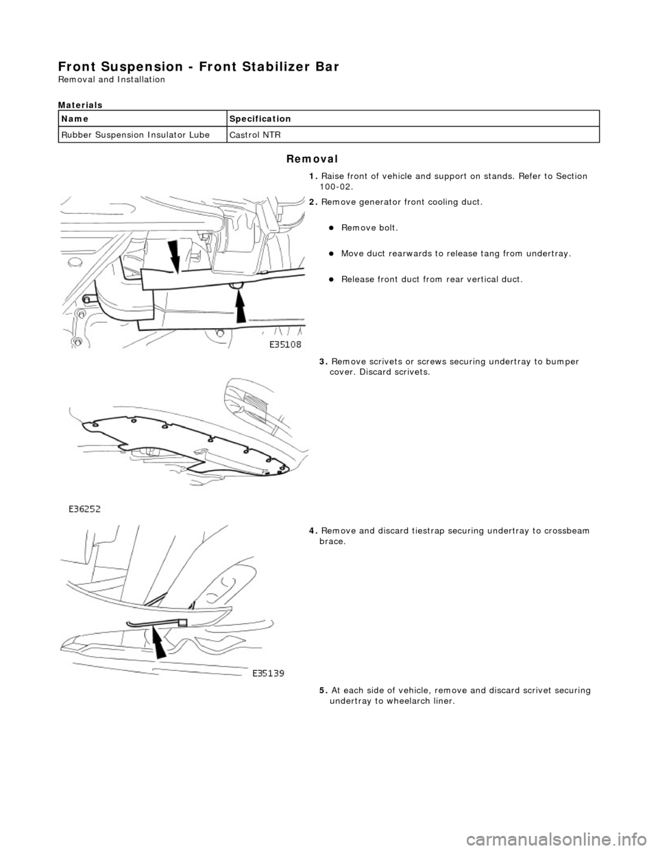
1. Raise front of vehicle and support on stands. Refer to Section
100-02.
2. R
emove generator front cooling duct.
пЃ¬Re
move bolt.
пЃ¬Move duct rea
rwards to rele
ase tang from undertray.
пЃ¬R
elease front duct from rear vertical duct.
3. R
emove scrivets or screws se
curing undertray to bumper
cover. Discard scrivets.
4. R
emove and discard tiestrap securing undertray to crossbeam
brace.
5. At each side of vehicle, remo ve and discard scrivet securing
undertray to wheelarch liner.
Page 121 of 2490
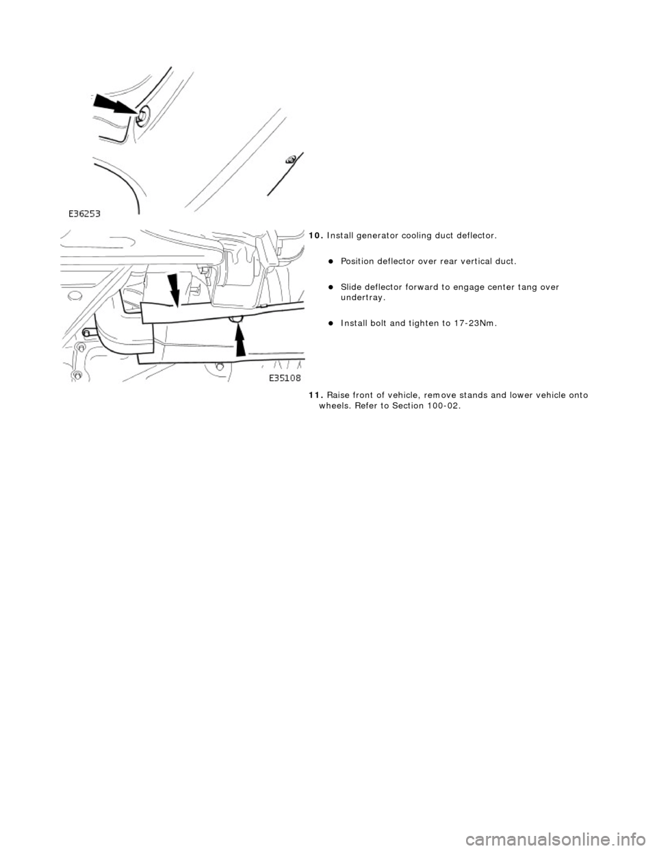
10
.
Install generator cool ing duct deflector.
пЃ¬Po
sition deflector over
rear vertical duct.
пЃ¬Sl
ide deflector forward to
engage center tang over
undertray.
пЃ¬Inst
all bolt and ti
ghten to 17-23Nm.
11. Raise front of vehicle, remove stands and lower vehicle onto
wheels. Refer to Section 100-02.
Page 122 of 2490
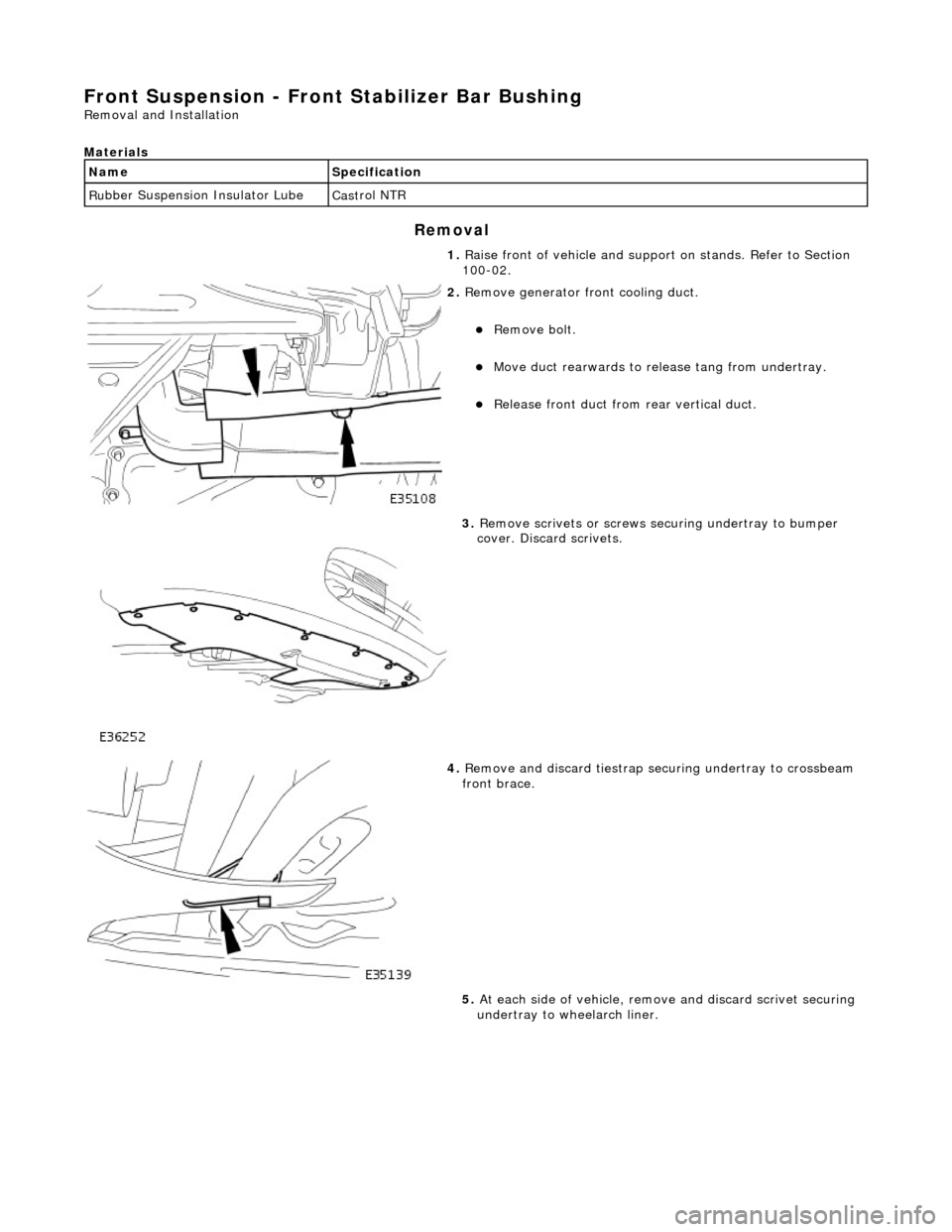
Front Suspension - Front Stabilizer B
ar Bushing
Re
mo
val and Installation
Materials
S p
ecification
Cas
t
rol NTR
Remov
a
l
Na
m
e
R
u
bber Suspension Insulator Lube
1. Raise front of vehicle and support on stands. Refer to Section
100-02.
2. Re
move generator front cooling duct.
пЃ¬Re
mo
ve bolt.
пЃ¬Move duct rea
r
wards to rele
ase tang from undertray.
пЃ¬Re
lease front duct from rear vertical duct.
3. Re
move scrivets or screws se
curing undertray to bumper
cover. Discard scrivets.
4. Re
move and discard tiestrap securing undertray to crossbeam
front brace.
5. At each side of vehicle, remo ve and discard scrivet securing
undertray to wheelarch liner.
Page 125 of 2490
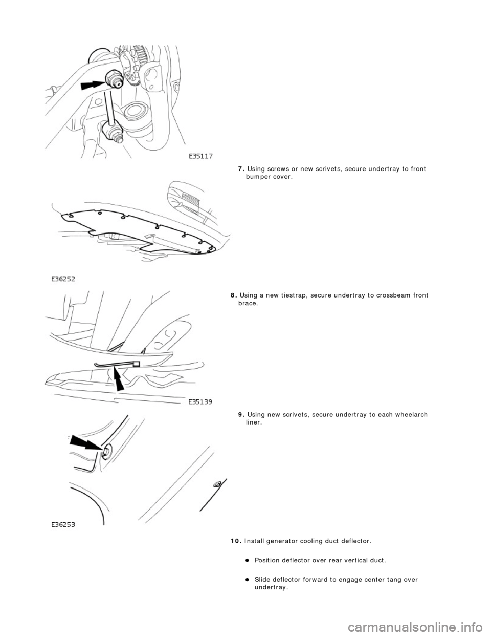
7. Using screws or new scrivets , secure undertray
to front
bumper cover.
8. Usi
ng a new tiestrap, secure undertray to crossbeam front
brace.
9. Usi
ng new scrivets, secure un
dertray to each wheelarch
liner.
10. Install generator cool ing duct deflector.
пЃ¬Po
sition deflector over
rear vertical duct.
пЃ¬Sl
ide deflector forward to
engage center tang over
undertray.
Page 522 of 2490
diverter val
ve (if fitted) and oil filter.
пЃ¬Main
bearings
which are grooved in the upper positions and plain in
the lower positions. They are manufactured from
aluminium / tin material.
пЃ¬A c
rankshaft with under
cuts and rolled fillets for extra strength.
пЃ¬Fracture
-split connecting rods in sintered-forged steel.
пЃ¬Brackets
bolted to the front of
the cylinder
block are used to mo unt all accessories.
пЃ¬A sin
gle, seven ribbed vee belt
drives the accessories.
пЃ¬An au
tomatic belt tensioner for the front accessory drive,
incorporating a wear indicator.
пЃ¬An advanced en
gine management system inco
rporating electronic throttle control.
пЃ¬The un
it meets the requirements of the CARB OBDII USA legislation.
Ancillary Systems
The an
ci
llary systems, driven by the engine, each have a
detailed Description and Operation along with Diagnostic
Procedures, and Removal and Installation instructions ; refer to the following sections of this manual:
пЃ¬Power Steeri
ng Pump - Section 211-02
пЃ¬Ai
r Conditioning Compressor - Sectio
n 412-03
пЃ¬Engine
C
ooling Pump - Section 303-03
пЃ¬Generator
- Sectio
n 414-02
The drive belt, idler pulley and automatic tensioner are described in Section 303-05.
The engine starting system is described in Section 303-06.
En
gine Management and Emission Control System
Engine Control Modu
le (ECM)
Engine
management and exhaust emissions are controlled by the ECM, which has the
following main functions:
пЃ¬Fu
el injection
пЃ¬Idle
s
peed
пЃ¬Ignition пЃ¬Ev
aporative loss system
пЃ¬Engine
cooling fans пЃ¬Clim
ate control compressor clutch demand
The microprocessor within the ECM receiv es signals from various sensors and other modules and uses a pre-determined
program to compute engine management functions.
Adaptive functions are incorporated in the ECM to cater for co ntinuous adjustments to its computations to suit prevailing
conditions. Because the system also controls emissions to suit all modes, neither CO levels nor idle speed require service
attention or adjustment, except if an error should occur.
On Board Diagnostics are controlled by the ECM with the continuous monitoring of incoming signals and the subsequent
verification against what the module expects to 'see'. Should a si gnal be incorrect or missing, the ECM will substitute a fixed
value to provide the 'limp home mode' and alert the driver of the problem. Fixed values may be adopted for:
пЃ¬Transmission oil
temperature
пЃ¬Mechanica
l
guar
d position
пЃ¬Throttle blade angle пЃ¬Camshaft position
пЃ¬Inta
k
e air temperature
Diagnostic trouble codes (DTC), including OBD II codes, are stored in the ECM memo ry and can be read by an appropriate
retrieval tool.
Should either the ECM or TCM fa il, ensure that the control housing cooling fan is operating correctly. Failure of the cooling
fan MUST be rectified before renewing a control module and details of a fa n failure should accompany a returned control
module.
Page 643 of 2490
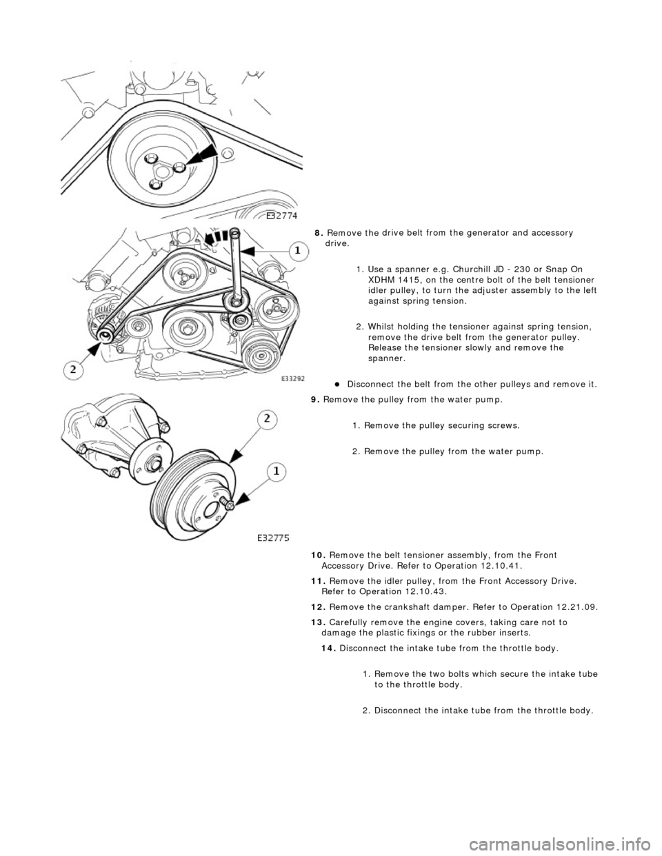
8. Remove the
drive belt from
the generator and accessory
drive.
1. Use a spanner e.g. Churchill JD - 230 or Snap On XDHM 1415, on the centre bo lt of the belt tensioner
idler pulley, to turn the adju ster assembly to the left
against spring tension.
2. Whilst holding the tensioner against spring tension, remove the drive belt from the generator pulley.
Release the tensioner sl owly and remove the
spanner.
пЃ¬D
isconnect the belt from the
other pulleys and remove it.
9. Re
move the pulley from the water pump.
1. Remove the pulley securing screws.
2. Remove the pulley from the water pump.
10. Remove the belt tensione r assembly, from the Front
Accessory Drive. Refer to Operation 12.10.41.
11. Remove the idler pulley, from the Front Accessory Drive.
Refer to Operation 12.10.43.
12. Remove the crankshaft damper. Refer to Operation 12.21.09.
13. Carefully remove the engine covers, taking care not to
damage the plasti c fixings or the rubber inserts.
14. Disconnect the intake tube from the throttle body.
1. Remove the two bolts which secure the intake tube to the throttle body.
2. Disconnect the intake tube from the throttle body.
Page 649 of 2490
15
.
Reconnect the air flow meter multi-plug.
16. Refit the engine covers.
17. Refit the crankshaft damper. Refer to Operation 12.21.09.
18. Refit the idler pulley, to the Front Accessory Drive. Refer to
Operation 12.10.43.
19. Refit the belt tensioner assembly, to the Front Accessory
Drive. Refer to Operation 12.10.41.
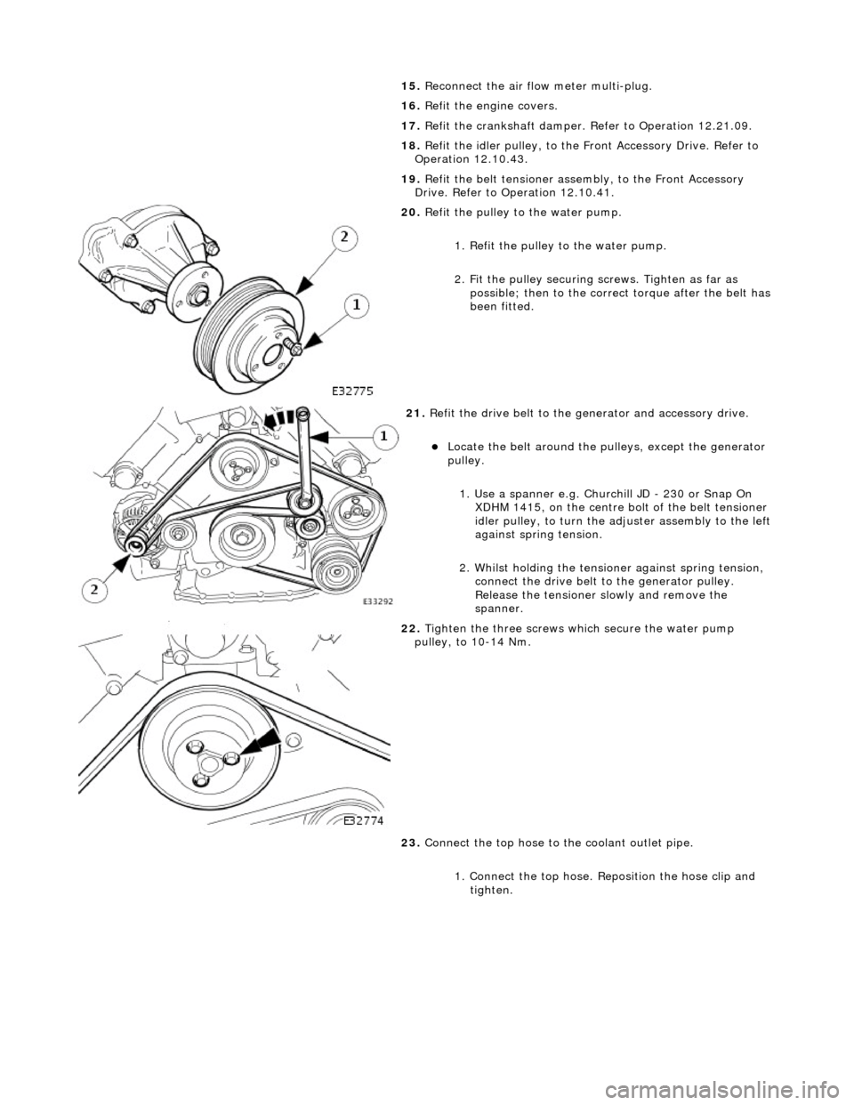
20
.
Refit the pulley to the water pump.
1. Refit the pulley to the water pump.
2. Fit the pulley securing screws. Tighten as far as
possible; then to the correct torque after the belt has
been fitted.
21
.
Refit the drive belt to the generator and accessory drive.
пЃ¬Locat
e the belt around the pulleys, except the generator
pulley.
1. Use a spanner e.g. Churchill JD - 230 or Snap On XDHM 1415, on the centre bo lt of the belt tensioner
idler pulley, to turn the adju ster assembly to the left
against spring tension.
2. Whilst holding the tensioner against spring tension, connect the drive belt to the generator pulley.
Release the tensioner sl owly and remove the
spanner.
22
.
Tighten the three screws wh ich secure the water pump
pulley, to 10-14 Nm.
23. Connect the top hose to the coolant outlet pipe.
1. Connect the top hose. Reposition the hose clip and tighten.