head bolt JAGUAR X308 1998 2.G Workshop Manual
[x] Cancel search | Manufacturer: JAGUAR, Model Year: 1998, Model line: X308, Model: JAGUAR X308 1998 2.GPages: 2490, PDF Size: 69.81 MB
Page 61 of 2490
Suspension System - General Information - Front Camber and Caster
Adjust
ment
Gen
eral Procedures
• NOTE: Before any work is commenced, th e vehicle must be checked to establish that it conforms to the Jaguar original
specification, e.g. wheels, ti res, tire pressures, etc.
• NOTE: The vehicle must be unladen and the fuel tank full when measuring suspension geometry.
1.
Road test the vehicle to establish the exact nature of the
complaint, e.g. pulling to one side, wander.
2. Measure the suspension geometry, fill in the 'Suspension
Geometry Record Form', and co ntact Jaguar Technical Support
for assistance.
3. Technical Support will give advice on the course of action to be
taken to rectify the problem.
4. Each lower wishbone pivots on and is secured to the front
crossbeam by two fulcrum bolts. A circular eccentric flange
formed under the hexagonal head of each fulcrum bolt, has
raised graduation marks to indicate radial position. A washer
with a 'D' shaped hole locates on a flat on the threaded section
of each bolt. This ensures that the washer rotates with the bolt,
maintaining an eccentric position corresponding with the
flanged head. The outer face of the washer is punch marked,
ensuring correct instal lation with the chamfered face inwards.
This permits the washer to rotate freely in the crossbeam cam
reaction plate during a djustm ent. Each fulcrum bolt and
washer are secured by a self locking nut.
On rotation of the bolt, lateral movement of the eccentric flange
and washer is restricted by the cam plate faces, forcing the bolt
shank to move laterally in the crossbeam slots. Lateral
movement of the bolt shank re sults in corresponding inward
and outward movement of th e wishbone arm, effecting
adjustment of wh eel alignment.
Rotation of the front fulcrum bolt principally adjusts wheel
caster angle, with a small amount of camber angle change.
Adjustment of the rear fulcrum bo lt mainly alters wheel camber
angle with a small amount of caster angle change.
On vehicles with VIN up to 833124, fulcrum bolt eccentric
flanges have raised graduation marks representing 15 degree
increments of bolt rotati on from 0 to 90 degrees.
On vehicles with VIN from 833125, the fulcrum bolt graduation
marks represent bolt shank ho rizontal movement in 1mm
increments from 0 to 3mm.
The upper wishbone and fulcrum shaft are not adjustable and
play no part in steering geometry adjustment.
Page 167 of 2490
Rear
Suspension - Rear Suspension
Description an
d Operation
Description
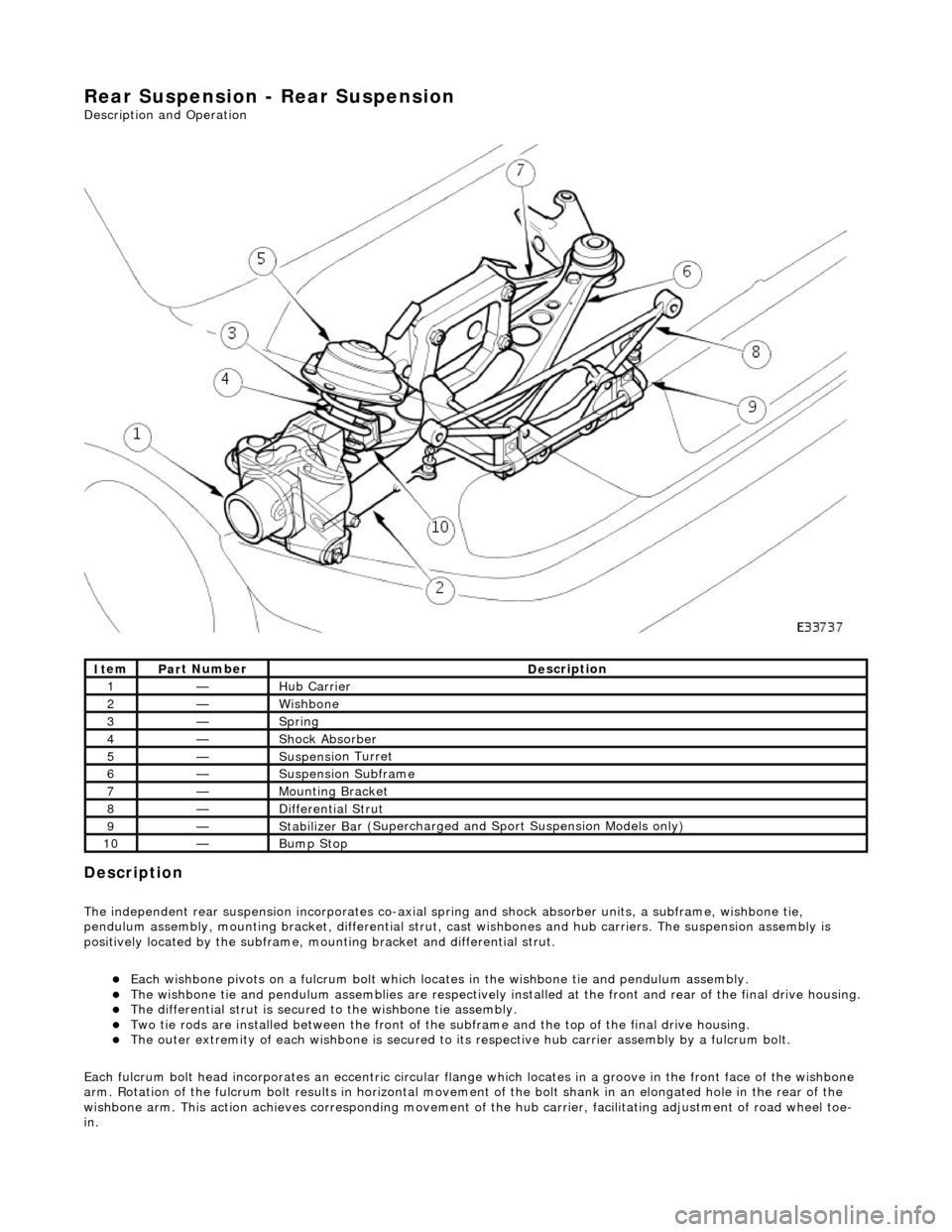
The i
ndependent rear suspension incorporates co-axial sp
ring and shock absorber units, a subframe, wishbone tie,
pendulum assembly, mounting brac ket, differential strut, cast wishbones and hub carriers. The suspension assembly is
positively located by the subframe, mounting bracket and differential strut.
Each wi
shbone pivots on a fulcru
m bolt which locates in the wishbone tie and pendulum assembly.
The wish
bone tie and pendulum assemblies are respectively in
stalled at the front and rear of the final drive housing.
The differential
strut is secured to the wishbone tie assembly.
Two ti
e rods are installed between the front of the
subframe and the top of the final drive housing.
The ou
ter extremity of each wishbone
is secured to its respective hub carrier assembly by a fulcrum bolt.
Each fulcrum bolt head incorporates an ec centric circular flange which locates in a groove in the front face of the wishbone
arm. Rotation of the fulcrum bolt results in horizontal movement of the bolt shank in an elongated hole in the rear of the
wishbone arm. This acti on achieves corresponding movement of the hub carrier, facilita ting adjustment of road wheel toe-
in.
It
em
Par
t Number
De
scription
1—Hub Carrier
2—Wi
shbone
3—Sprin
g
4—Shock Absorber
5—Suspensi
on Turret
6—Suspensi
on Subframe
7—Moun
ting Bracket
8—D
ifferential Strut
9—Stabilizer Ba
r (Supercharged and
Sport Suspension Models only)
10—Bum
p Stop
Page 288 of 2490
Re
ar Drive Axle/Differential - Axle Shaft
In-v
ehic
le Repair
Remov
a
l
S
p
ecial Tool(s)
Hub remover
2
04-011
Thread protector
JD
1D
/ 7
1. Disc
onnect the battery ground lead.
2. Support the vehicle at the rear and remove the appropriate
rear road wheel.
3. Remove and discard the hub nut, apply the brakes to prevent
rotation.
4. Remove the brake caliper in acco rdance with 70.55.03, but do
not disconnect the hydraulics.
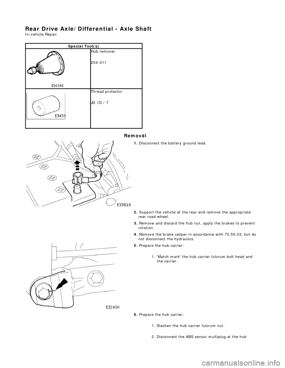
5. Pr
epare the hub carrier.
1. 'Match mark' the hub carr ier fulcrum bolt head and
the carrier.
6. Prepare the hub carrier.
1. Slacken the hub ca rrier fulcrum nut.
2. Disconnect the ABS sensor multiplug at the hub
Page 364 of 2490
Rear Disc Brake -
Lubric
ants, Fluids, Sealants and Adhesives
CAUTI
O
N: Do not use brake fluid ITT Supe
r Dot 4 on 2006my vehicles onwards. Fa ilure to follow this instruction may
result in damage to the vehicle.
• NOTE: Brake fluid ITT Super Dot 4 has now been superseded by Shell ESL Super Dot 4 which is the Jaguar recommended
brake fluid. Shell ESL Super Dot 4 can be used on all model years.
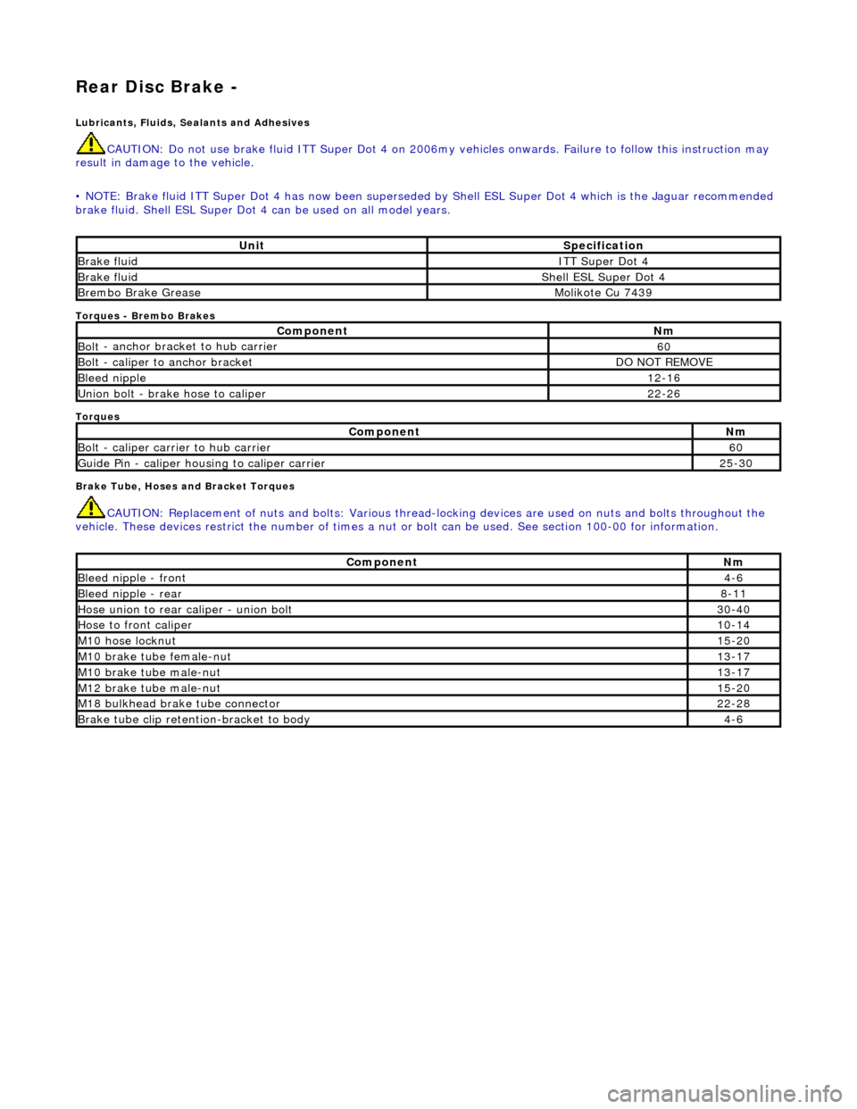
Torques
- Brembo Brakes
Torques
Brake Tube, Hoses and Bracket Torques
CAUTIO
N: Replacement of
nuts and bolts: Various thread-locking devices are used on nuts and bolts throughout the
vehicle. These devices restrict the number of times a nut or bolt can be used. See section 100-00 for information.
UnitS p
ecification
Brake flu
i
d
ITT Supe
r Dot 4
Brake flui
d
Shell E
SL Supe
r Dot 4
Brem
bo Brake G
rease
Mol
i
kote Cu 7439
Com
p
onent
Nm
Bol
t
- anchor bracket to hub carrier
60
B
o
lt - caliper to anchor bracket
DO
N
OT REMOVE
Bleed n
i
pple
12
-16
Un
ion bolt - brake hose to caliper
22
-26
Com p
onent
Nm
Bol
t
- caliper carrier to hub carrier
60
Guide
Pi
n - caliper housing to caliper carrier
25
-30
Comp
onent
Nm
Bleed ni
pple - front
4-6
Bleed ni
pple - rear
8-11
Hose union to rear cal
i
per - union bolt
30
-40
Hose to fr ont cal
iper
10
-14
M1 0 h
ose locknut
15
-20
M10 brake
tube female-nut
13
-17
M10 brake
tube male-nut
13
-17
M12 brake
tube male-nut
15
-20
M18 bu
lkhead brake tube connector
22
-28
Brake tube clip retention -
bracket to body
4-
6
Page 460 of 2490
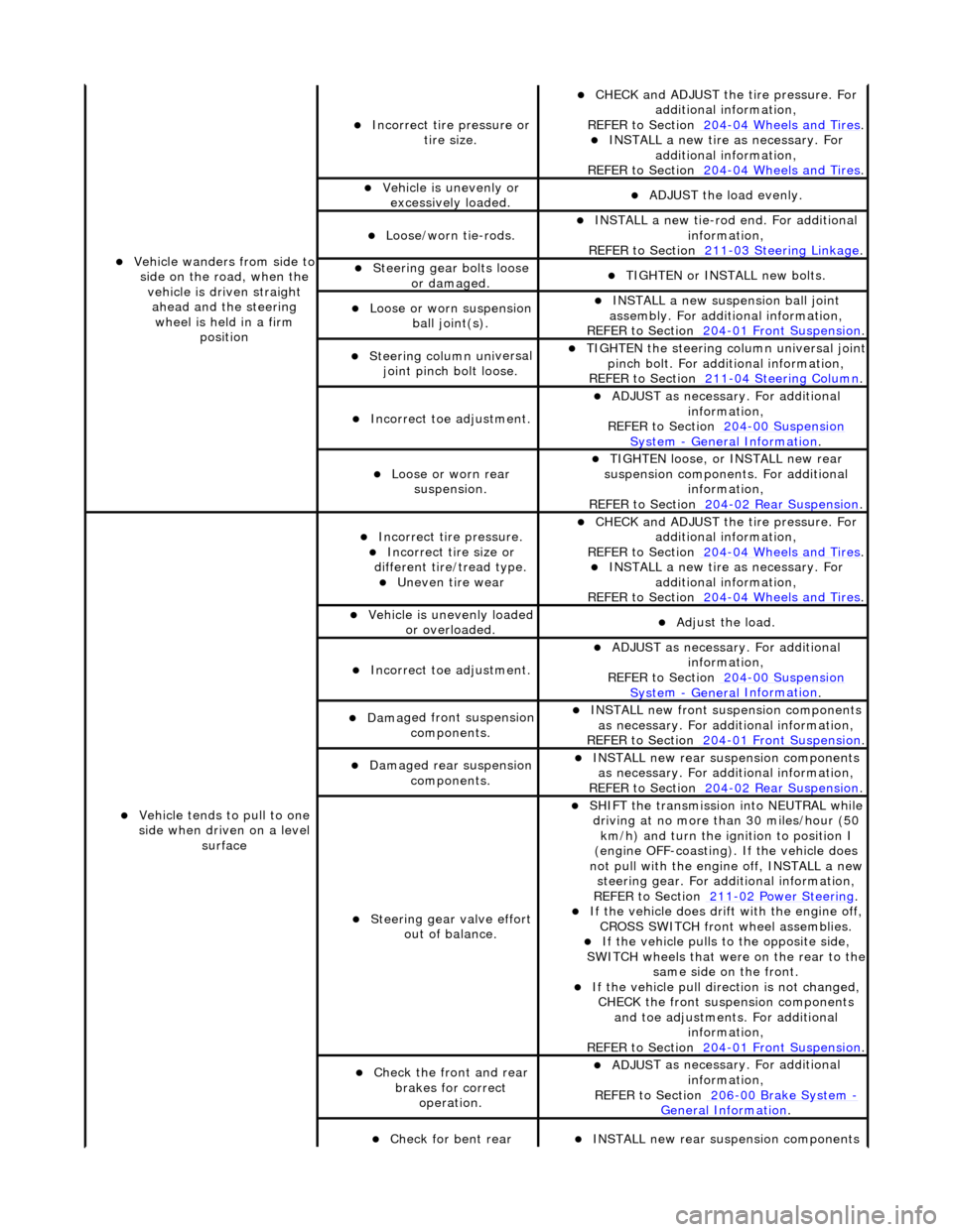
Vehicl
e wanders from side to
side on the road, when the vehicle is driven straight ahead and the steering wheel is held in a firm position
Incorrect ti re
pressure or
tire size.
CHECK and ADJ
UST the tire pressure. For
additional information,
REFER to Section 204
-0 4
Wheels and Tires
. IN
ST
ALL a new tire as necessary. For
additional information,
REFER to Section 204
-0 4
Wheels and Tires
.
Vehi
cl
e is unevenly or
excessively loaded.
A D
JUST the load evenly.
Loose/worn ti
e-
rods.
INST
ALL a ne
w tie-rod
end. For additional
information,
REFER to Section 211
-0 3
Steering Linkage
.
Steeri
ng gear bolts loose
o
r damaged.
TIGHTE
N or INSTALL
new bolts.
Loose or worn suspensi
on
ball jo
int(s).
INST
ALL a ne
w suspension ball joint
assembly. For additional information,
REFER to Section 204
-01 Fron
t Suspension
.
Steeri
ng column uni
versal
joint pinch bolt loose.
TI G
HTEN the steering column universal joint
pinch bolt. For additi onal information,
REFER to Section 211
-0 4
Steering Column
.
Incorre
ct
toe adjustment.
ADJUS
T as necessary. For additional
information,
REFER to Section 204
-00 Sus
pension
Sy
ste
m
- General
Information
.
Loose or worn rear
susp
ension.
TIGHTEN
loose, or IN
STALL new rear
suspension components. For additional information,
REFER to Section 204
-0 2
Rear Suspension
.
Vehicle t
e
nds to pull to one
side when driven on a level surface
Incorrect ti
re pressure.
Incorrect
ti
re size or
different tire/tread type.
Uneven tire wear
CHECK and ADJ
UST the tire pressure. For
additional information,
REFER to Section 204
-0 4
Wheels and Tires
. IN
ST
ALL a new tire as necessary. For
additional information,
REFER to Section 204
-04
Wheels and Tires
.
Vehicl
e is unevenly loaded
or overloaded.
Adjust the load
.
Incorre
ct
toe adjustment.
ADJUS
T as necessary. For additional
information,
REFER to Section 204
-00 Sus
pension
Sy
ste
m
- General
Information
.
Dam
a
ged front suspension
components.
I N
STALL new front suspension components
as necessary. For addi tional information,
REFER to Section 204
-01 Fron
t Suspension
.
Damaged rear
suspen
sion
components.
INST ALL ne
w rear suspension components
as necessary. For addi tional information,
REFER to Section 204
-0 2
Rear Suspension
.
Steeri
ng gear val
ve effort
out of balance.
SHIF T the
transmission into NEUTRAL while
driving at no more than 30 miles/hour (50 km/h) and turn the ignition to position I
(engine OFF-coasting). If the vehicle does
not pull with the engine off, INSTALL a new steering gear. For additional information,
REF E
R to Section 211
-0
2
Power Steering
. If t
he
vehicle does drift with the engine off,
CROSS SWITCH front wheel assemblies.
If the
vehicle pulls to
the opposite side,
SWITCH wheels that were on the rear to the
same side on the front.
If the v
ehicle pull dire
ction is not changed,
CHECK the front susp ension components
and toe adjustments. For additional information,
REFER to Section 204
-01 Fron
t Suspension
.
Chec
k
the front and rear
brakes for correct operation.
ADJUS
T as necessary. For additional
information,
REFER to Section 206
-0 0
Brake System
-
General Informati on.
Check fo
r bent rear
INST
ALL ne
w rear suspension components
Page 530 of 2490
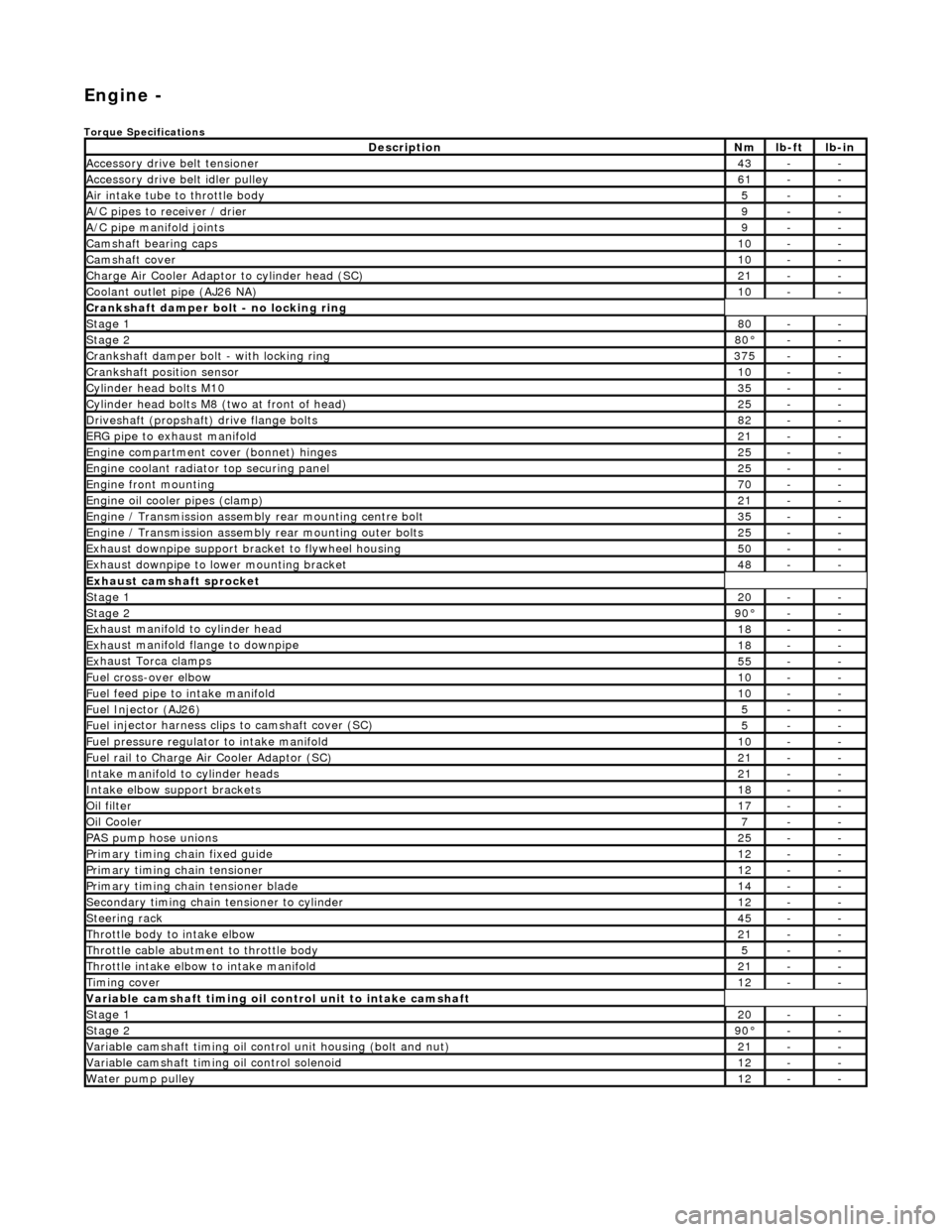
Engi
ne -
Torqu
e Specifications
De
s
cription
Nmlb
-
ft
lb
-
in
A
ccessory
drive belt tensioner
43--
A
ccessory
drive belt idler pulley
61--
Air in
ta
ke tube to throttle body
5--
A/C
pipes t
o receiver / drier
9--
A/C pipe m
anifold joints
9--
Camsh
aft bearin
g caps10--
Ca
msh
aft cove
r10--
Ch
arge Air Co
oler Adaptor to cylinder head (SC)
21--
Co
olan
t outlet pipe (AJ26 NA)
10--
Cran
kshaft damper bolt - no lockin
g ring
St
ag
e 1
80--
Stag
e 2
80°--
C
r
ankshaft damper bolt - with locking ring
37
5--
Cra
nkshaft position sensor
10--
Cy
li
nder head bolts M10
35--
Cy
lin
der head bolts M8 (two at front of head)
25--
Driv
es
haft (propshaft) drive flan
ge bo
l
ts
82--
ERG p
i
pe to exhaust manifold
21--
Engi
ne compartment cover (bonnet) hinges
25--
En
gine
coolant radiator top securing panel
25--
E
ng
ine front mounting
70--
En
gine
oil cooler pipes (clamp)
21--
En
gi
ne / Transmission assembly rear mounting centre bolt
35--
En
gi
ne / Transmission assembly rear mounting outer bolts
25--
Ex
ha
ust downpipe support bracket to flywheel housing
50--
Ex
ha
ust downpipe to lower mounting bracket
48--
E
x
haust camshaft sprocket
St
age 120--
Stage 290 °--
Ex
haust manifold to cylinder head
18--
Ex
ha
ust manifold flange to downpipe
18--
E
x
haust Torca clamps
55--
Fuel cross-over elbo
w
10--
Fu
el f
eed pipe to intake manifold
10--
Fuel
Injector (AJ
26)
5--
Fuel
injector ha
rness clips to camshaft cover (SC)
5--
Fu
el p
ressure re
gu
l
ator to intake manifold
10--
F
u
el rail to Char
ge
A
ir Cooler Adaptor (SC)
21--
In
ta
ke manifold to cylinder heads
21--
Inta
ke elbow support brackets
18--
Oil f
i
lter
17--
Oil C
o
oler
7--
P
AS pu
mp hose unions
25--
P
r
imary timing chain fixed guide
12--
P
r
imary timing chain tensioner
12--
Pr
imary timing chain tensioner blade
14--
S
e
condary timing chain tensioner to cylinder
12--
S
t
eerin
g ra
ck45--
Thro
ttle body to intake elbow
21--
Th
ro
ttle cable abutment to throttle body
5--
Th
ro
ttle intake elbow to intake manifold
21--
Ti
mi
ng cover
12--
Variable camshaft t
i
ming oil control unit to intake camshaft
St
ag
e 1
20--
St
ag
e 2
90
°--
Var
iable camshaft timing oil control unit housing (bolt and nut)
21--
Va
ria
ble camshaft timi
ng oil control solenoid
12--
Wa
ter pump pulley
12--
Page 549 of 2490
5.
Repeat steps 2 to 4 three
more times until all sixteen
valves on the first cylinder head have been adjusted.
6. Repeat steps 1 to 5 for the other cylinder head.
7. Remove all equipment and reassemble the engine.
8. The following instructions describe the PROCEDURE FOR
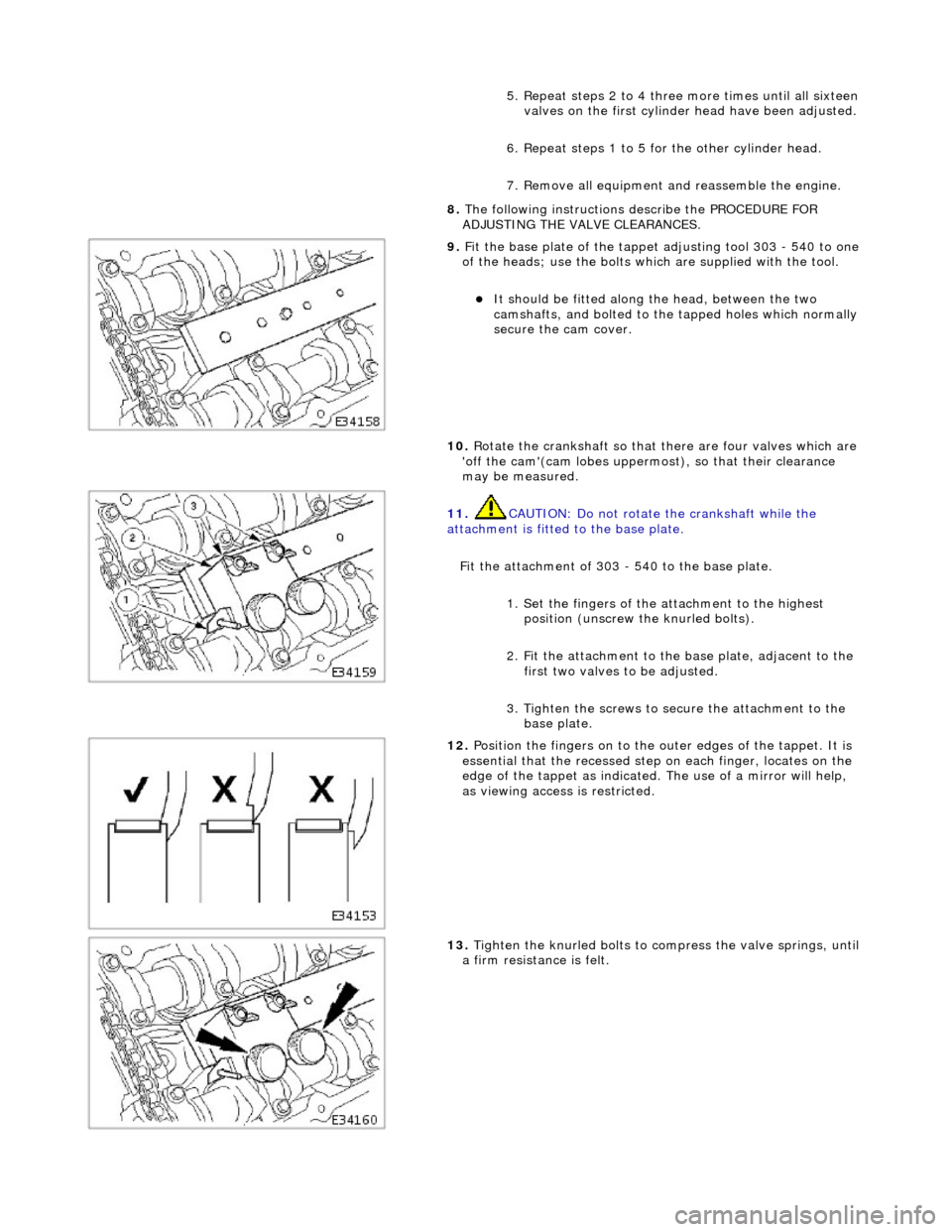
ADJUSTING THE VALVE CLEARANCES.
9. F
it the base plate of the tappet
adjusting tool 303 - 540 to one
of the heads; use the bolts which are supplied with the tool.
It
should be fitted along the head, between the two
camshafts, and bolted to the tapped holes which normally
secure the cam cover.
10. Rotate the crankshaft so that there are four valves which are
'off the cam'(cam lobes uppermos t), so that their clearance
may be measured.
11
.
CAUTION: Do not rotate the crankshaft while the
attachment is fitted to the base plate.
Fit the attachment of 303 - 540 to the base plate. 1. Set the fingers of the attachment to the highest position (unscrew the knurled bolts).
2. Fit the attachment to the base plate, adjacent to the first two valves to be adjusted.
3. Tighten the screws to secure the attachment to the base plate.
12
.
Position the fingers on to the outer edges of the tappet. It is
essential that the recessed step on each finger, locates on the
edge of the tappet as indicated. The use of a mirror will help,
as viewing access is restricted.
13
.
Tighten the knurled bolts to compress the valve springs, until
a firm resistan ce is felt.
Page 553 of 2490
1
2.60.48.
12. Install the old bolt which secu red the crankshaft damper, to
allow the crankshaft to be rotated. Use a new bolt on final
installation.
13. The following group of instructions (until stated otherwise)
describe the procedure to rene w the bearing shells in one
connecting rod. Repeat the instructions as necessary.
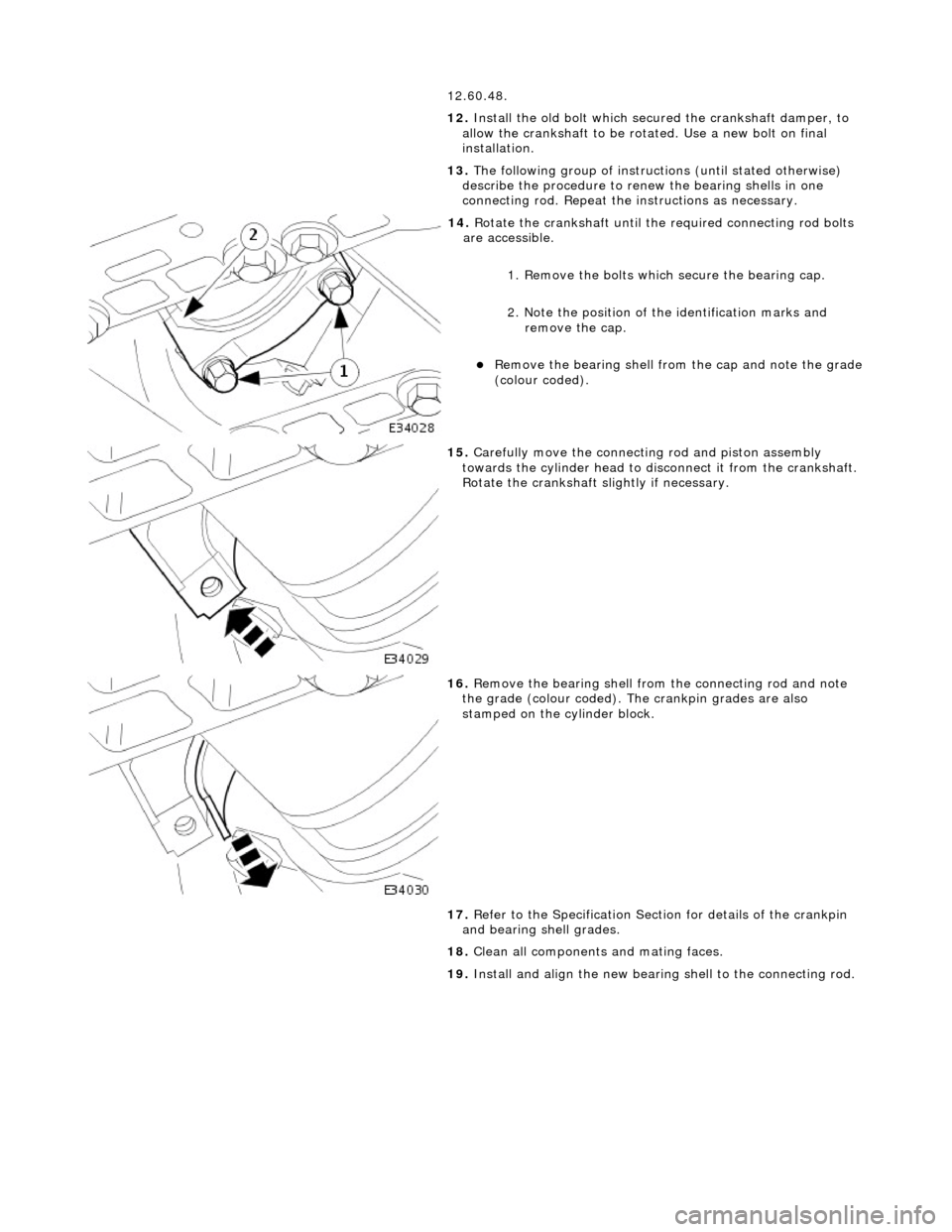
14
.
Rotate the crankshaft until th e required connecting rod bolts
are accessible.
1. Remove the bolts which secure the bearing cap.
2. Note the position of the identification marks and remove the cap.
Remove the
bearing shell from the cap and note the grade
(colour coded).
15
.
Carefully move the connecting rod and piston assembly
towards the cylinder head to di sconnect it from the crankshaft.
Rotate the crankshaft slightly if necessary.
16
.
Remove the bearing shell from the connecting rod and note
the grade (colour coded). The crankpin grades are also
stamped on the cylinder block.
17. Refer to the Specification Sectio n for details of the crankpin
and bearing shell grades.
18. Clean all components and mating faces.
19. Install and align the new bearing shell to the connecting rod.
Page 558 of 2490
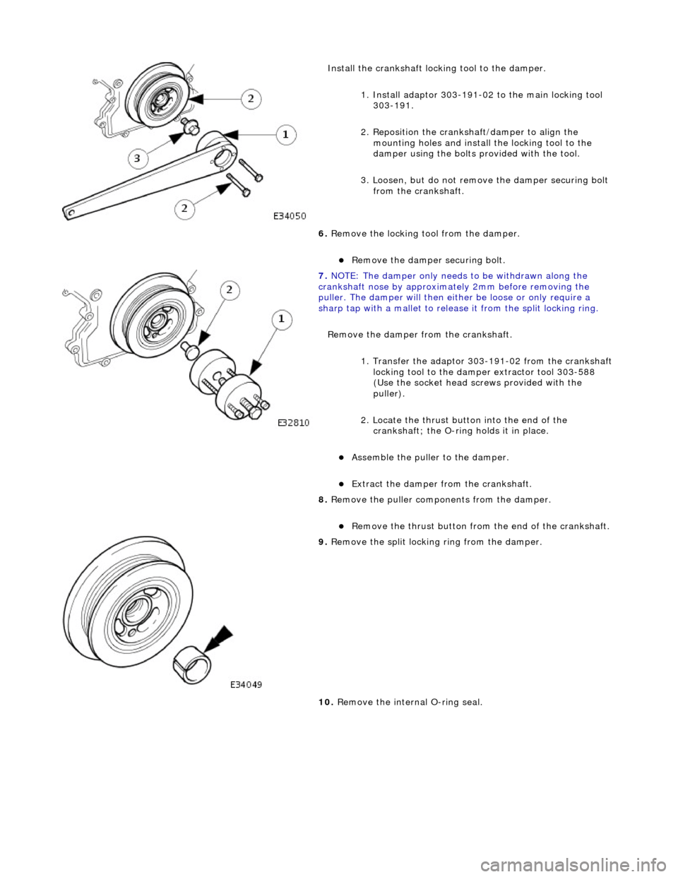
Instal
l the crankshaft locking tool to the damper.
1. Install adaptor 303-191-02 to the main locking tool 303-191.
2. Reposition the cranks haft/damper to align the
mounting holes and install the locking tool to the
damper using the bolts provided with the tool.
3. Loosen, but do not remove the damper securing bolt
from the crankshaft.
6. Remove the locking tool from the damper.
Remove
the damper securing bolt.
7. NOTE : Th
e damper only needs to be withdrawn along the
crankshaft nose by approximat ely 2mm before removing the
puller. The damper will then either be loose or only require a
sharp tap with a mallet to release it from the split locking ring.
Remove the damper from the crankshaft.
1. Transfer the adaptor 303 -191-02 from the crankshaft
locking tool to the damper extractor tool 303-588
(Use the socket head screws provided with the
puller).
2. Locate the thrust button into the end of the crankshaft; the O-ring holds it in place.
Ass
emble the puller to the damper.
Ex
trac
t the damper from the crankshaft.
8. Remove the puller components from the damper.
Re
move the thrust button from the end of the crankshaft.
9. Re
move the split locking ring from the damper.
10. Remove the internal O-ring seal.
Page 562 of 2490
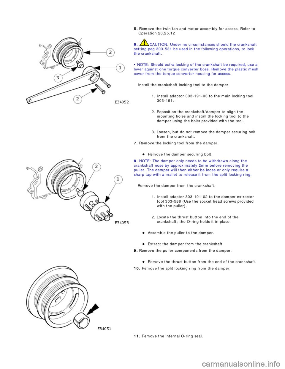
5. Re
move the twin fan and motor
assembly for access. Refer to
Operation 26.25.12
6. CAUTIO
N: Under no circumstan
ces should the crankshaft
setting peg 303-531 be used in the following operations, to lock
the crankshaft.
• NOTE: Should extra locking of the crankshaft be required, use a
lever against one torque converte r boss. Remove the plastic mesh
cover from the torque converter housing for access.
Install the crankshaft locking tool to the damper. 1. Install adaptor 303-191-03 to the main locking tool 303-191.
2. Reposition the cranks haft/damper to align the
mounting holes and install the locking tool to the
damper using the bolts provided with the tool.
3. Loosen, but do not remove the damper securing bolt
from the crankshaft.
7. Re
move the locking tool from the damper.
Re
move
the damper securing bolt.
8. NOTE : Th
e damper only needs to be withdrawn along the
crankshaft nose by approximat ely 2mm before removing the
puller. The damper will then either be loose or only require a
sharp tap with a mallet to release it from the split locking ring.
Remove the damper from the crankshaft.
1. Install adaptor 303-191-02 to the damper extractor tool 303-588 (Use the socket head screws provided
with the puller).
2. Locate the thrust button into the end of the crankshaft; the O-ring holds it in place.
Ass
emble the puller to the damper.
Ex
trac
t the damper from the crankshaft.
9. Remove the puller components from the damper.
Re
move the thrust button from the end of the crankshaft.
10 . R
emove the split locking ring from the damper.
11. Remove the internal O-ring seal.