rear bumper JAGUAR X308 1998 2.G Workshop Manual
[x] Cancel search | Manufacturer: JAGUAR, Model Year: 1998, Model line: X308, Model: JAGUAR X308 1998 2.GPages: 2490, PDF Size: 69.81 MB
Page 33 of 2490

501‐17: Roof Open
ing
Panel
Description and Operation
Roof Opening Panel
General Procedures
Motor Synchronization (76.82.48)
Roof Opening Panel Alignment
Removal and Installation
Roof Opening Panel (76.82.05)
Roof Opening Panel Frame (76.82.01)
Roof Opening Panel Module (86.76.07)
Roof Opening Panel Motor (86.76.01)
Roof Opening Panel Shie
ld (76.82.06)
Roof Opening Panel Trim
Roof Opening Panel Weatherstrip (76.82.15)
501‐19: Bumpers
Specification
Description and Operation
Bumpers
Removal and Installation
Front Bumper (76.22.08)
Front Bumper and Bumper Cover (76.22.08)
Front Bumper Cover (76.22.78)
Front Bumper Isolator (76.22.31)
Rear Bumper (76.22.27) (76.22.52)
Rear Bumper Co
ver (76.22.74) (76.22.77)
Rear Bumper Isolator (76.22.70)
501‐20A : Safety Belt System
Specification
Description and Operation
Safety Belt System
Removal and Installation
Front Safety Belt Retractor (76.73.10)
Rear Safety Belt Retractor (76.73.18)
Safety Belt Shoulder Height Adjuster (76.73.12)
Page 55 of 2490
P
arts List
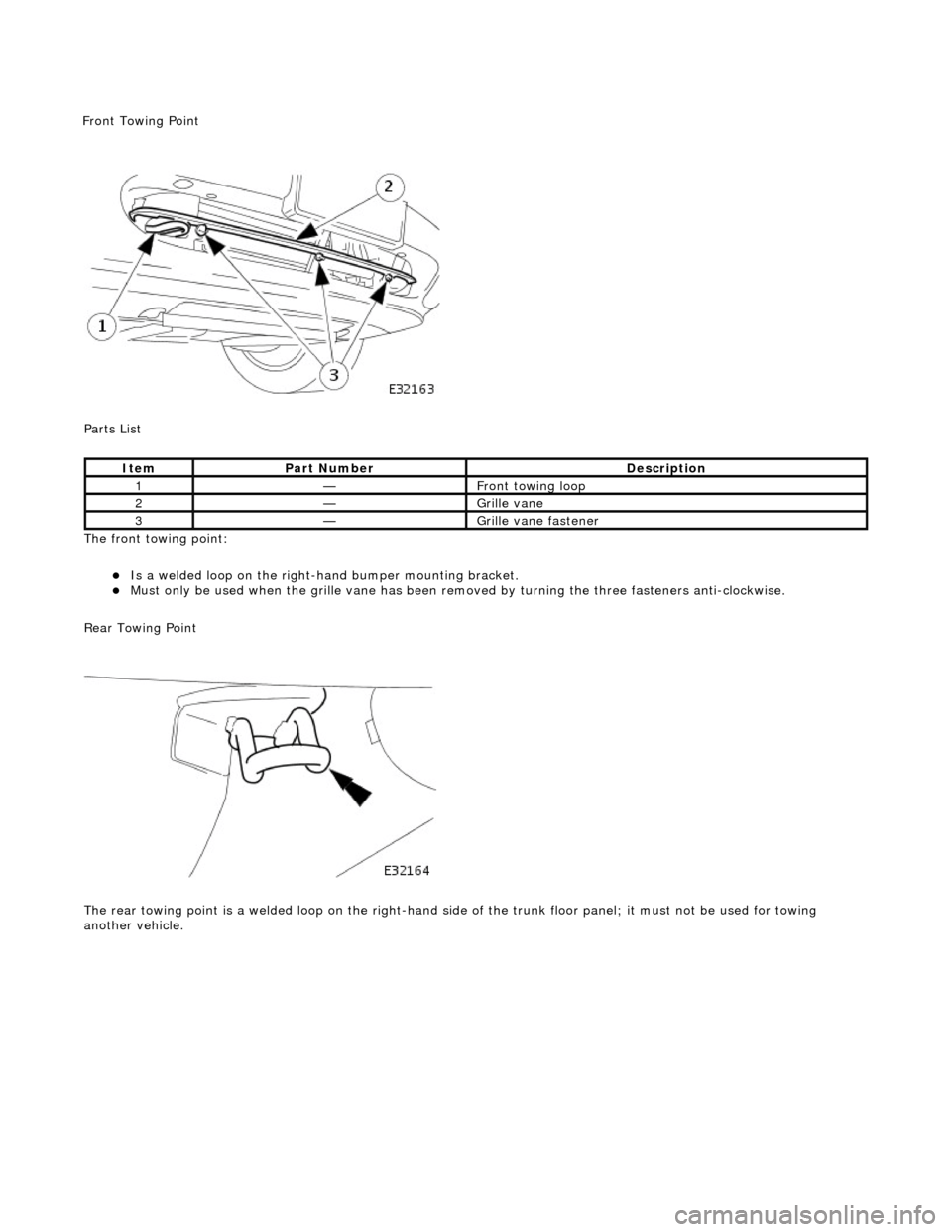
The front towing point:
Is a welded loop on the ri
ght-ha
nd bumper mounting bracket.
Mus
t only be used when the grille
vane has been removed by turning the three fasteners anti-clockwise.
Rear Towing Point
The rear towing point is a welded loop on the right-hand side of the trunk floor panel; it must not be used for towing
another vehicle.
It
em
Par
t Number
De
scription
1—Fr
ont towing loop
2—Gr
ille vane
3—Gr
ille vane fastener
F
ront Towing Point
Page 117 of 2490
Front Suspension - Fro
nt Stabilizer Bar
Re
moval and Installation
Materials
S
pecification
Cas
trol NTR
Remov
al
Na
me
R
ubber Suspension Insulator Lube
1. Raise front of vehicle and support on stands. Refer to Section
100-02.
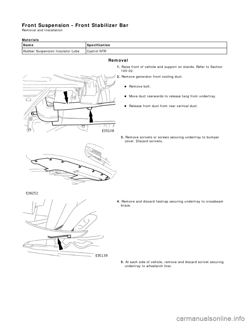
2. R
emove generator front cooling duct.
Re
move bolt.
Move duct rea
rwards to rele
ase tang from undertray.
R
elease front duct from rear vertical duct.
3. R
emove scrivets or screws se
curing undertray to bumper
cover. Discard scrivets.
4. R
emove and discard tiestrap securing undertray to crossbeam
brace.
5. At each side of vehicle, remo ve and discard scrivet securing
undertray to wheelarch liner.
Page 122 of 2490
Front Suspension - Front Stabilizer B
ar Bushing
Re
mo
val and Installation
Materials
S p
ecification
Cas
t
rol NTR
Remov
a
l
Na
m
e
R
u
bber Suspension Insulator Lube
1. Raise front of vehicle and support on stands. Refer to Section
100-02.
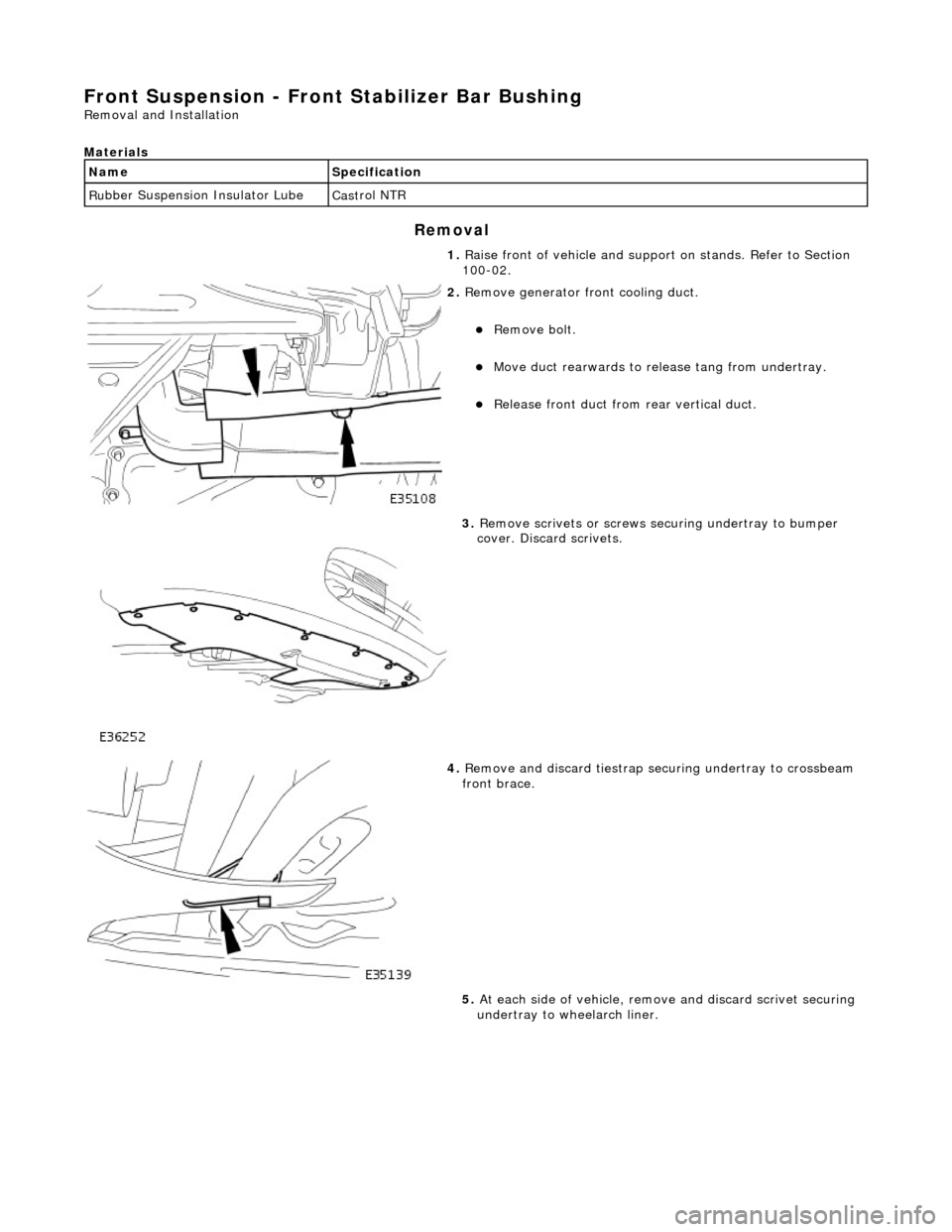
2. Re
move generator front cooling duct.
Re
mo
ve bolt.
Move duct rea
r
wards to rele
ase tang from undertray.
Re
lease front duct from rear vertical duct.
3. Re
move scrivets or screws se
curing undertray to bumper
cover. Discard scrivets.
4. Re
move and discard tiestrap securing undertray to crossbeam
front brace.
5. At each side of vehicle, remo ve and discard scrivet securing
undertray to wheelarch liner.
Page 125 of 2490
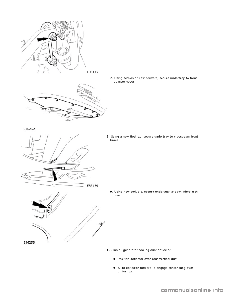
7. Using screws or new scrivets , secure undertray
to front
bumper cover.
8. Usi
ng a new tiestrap, secure undertray to crossbeam front
brace.
9. Usi
ng new scrivets, secure un
dertray to each wheelarch
liner.
10. Install generator cool ing duct deflector.
Po
sition deflector over
rear vertical duct.
Sl
ide deflector forward to
engage center tang over
undertray.
Page 1527 of 2490

Rear Muffler Assembly
The left-hand and right-hand rear muffler assemblies comprise:
Absorption type muffler. Inlet pipe and tailpipe welded to the muffler. Tailpipe bright finisher integral with the tailpipe.
Tailpipe Clearance to Moulded Bumper
Page 1869 of 2490
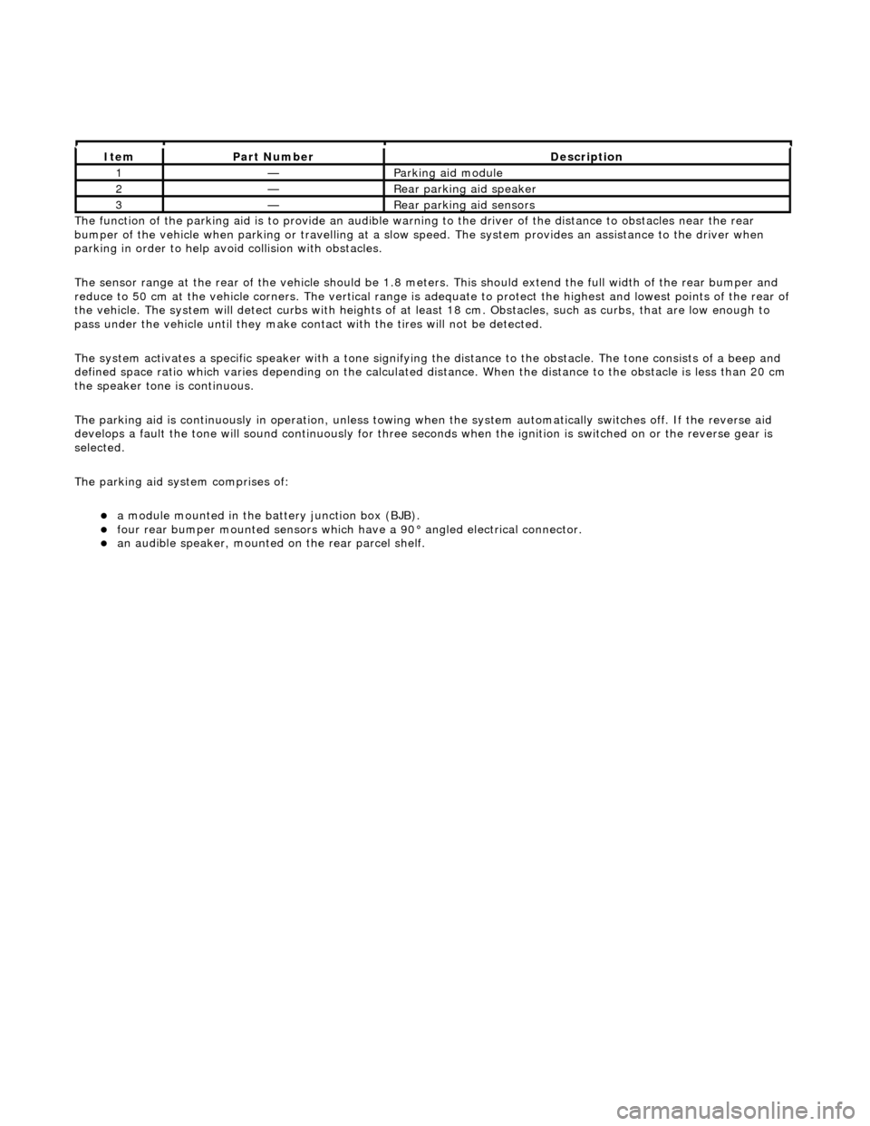
The functi
on of the parking aid is to prov
ide an audible warning to the driver of the distance to obstacles near the rear
bumper of the vehicle when parking or travelling at a slow sp eed. The system provides an assistance to the driver when
parking in order to help avoid collision with obstacles.
The sensor range at the rear of the vehicl e should be 1.8 meters. This should extend the full width of the rear bumper and
reduce to 50 cm at the vehicle co rners. The vertical range is adequate to protec t the highest and lowest points of the rear of
the vehicle. The system will detect curbs with heights of at least 18 cm. Obstacles, such as curbs, that are low enough to
pass under the vehicle until they make contact with the tires will not be detected.
The system activates a specific speaker with a tone signifying the distance to the obstacle. The tone consists of a beep and
defined space ratio which varies depending on the calculated distance. When the distance to the obstacle is less than 20 cm
the speaker tone is continuous.
The parking aid is continuously in operation, unless towing wh en the system automatically switches off. If the reverse aid
develops a fault the tone will sound continuously for three seconds when the igni tion is switched on or the reverse gear is
selected.
The parking aid system comprises of:
a
module mounted in the batte
ry junction box (BJB).
fou
r rear bumper mounted sensors which have a 90° angled electrical connector.
an audible speaker, moun
ted on
the rear parcel shelf.
It
em
Par
t Number
De
scription
1—Parkin
g aid module
2—Rear
parking aid speaker
3—Rear
parking aid sensors
Page 1920 of 2490
Direction indicator and side marker lamps
Each front direction indicator and side marker lamp is retained in the bumper cover by a lug at one end and a spring clip at
the other end. The side marker lamps are not electrically connected for certain markets.
The side repeater lamps are secured by sp ring clips on the lower edge of the lamp unit. In certain markets Jaguar leaper
badges are substituted for side repeater lamps.
Fog lamps
The fog lamps are located in recesses in the front bump er and secured by three screws. The la mps which are not
interchangeable left to right, are accessed from the rear of the bumper.
Operation
All lamps are controlled by the BPM which provides an appropriate output in response to an input received when a selected
switch is operated.
All lamps receive an input direct from th e BPM with the exception of the main be am, dip beam and front fog lamps which
receive an input from the BPM vi a the respective relays and fuses; refer to section 418-01.
Fault analysis must be undertaken using the PDU. Refer to Diagnosis and Testing.
Consult the relevant Electrical Guid e for details of circuit operation.
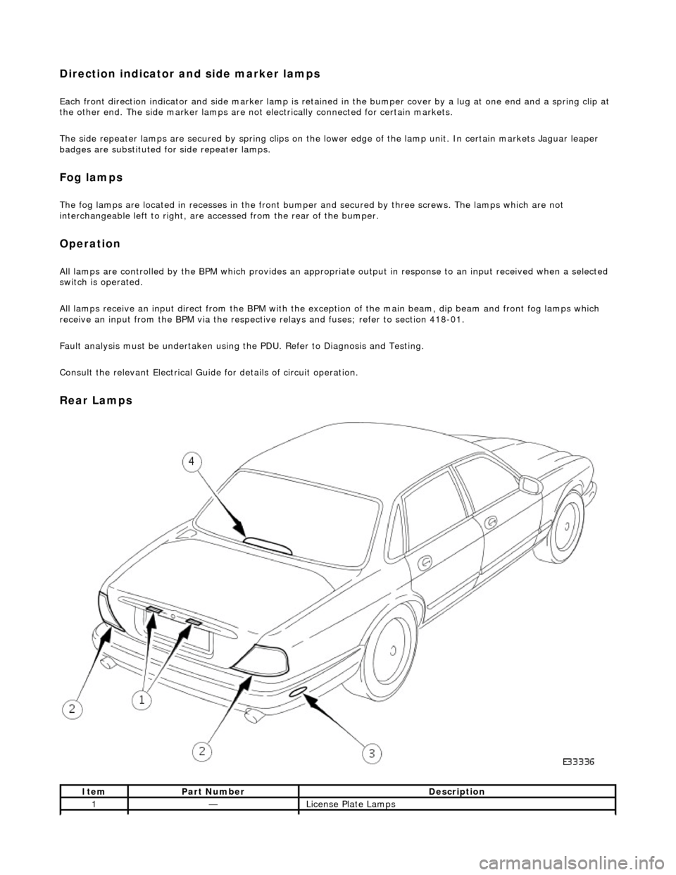
Rear Lamps
ItemPart NumberDescription
1—License Plate Lamps
Page 1921 of 2490
License plate lamps
Each license plate bulb is accessible after removing the relevant lens. The license plate lamps can be accessed following
removal of the trunk lid liner and upper trim finisher.
Rear lamp assembly
Each rear lamp assembly incorporates a stop/tail lamp, a fog lamp, a reversing lamp and a direction indicator lamp. Access
for bulb replacement is from the trunk.
Side markers
Each side marker is retained in the bumper cover by a lug on one end of the unit and a spring clip at the other end. The unit is not electrically connected for all markets.
High mounted stop lamp
The high mounted stop lamp (HMSL) is secu red to studs on the center lower edge of the backlight and provides illumination
using five bulbs.
Operation
All lamps are controlled by the BPM which pr ovides an appropriate output in response to an input received when a selected
switch is operated.
The side marker lamps receive an input from the BPM via relay 3 and fuse F21. The license plate lamps receive an input
from the BPM via relay 3 and fuse F19. The rela y and fuses are located in the trunk fuse-box.
The tail lamps receive an input direct from the BPM.
The stop, reversing and rear fog lamps are controlled by the security and locking module (SLM) which receives inputs via
the SCP network from the BPM.
The HMSL is not controlled by the SLM; it receives input from the brake switch via relay 5 and fuse F8 in the trunk fuse-box.
The BPM and SLM monitor the stop lamps (n ot HMSL) and tail lamps for failure.
Fault analysis must be undertaken using the PDU, refer to Diagnosis and Testing.
Consult the relevant Electrical Guid e for details of circuit operation.
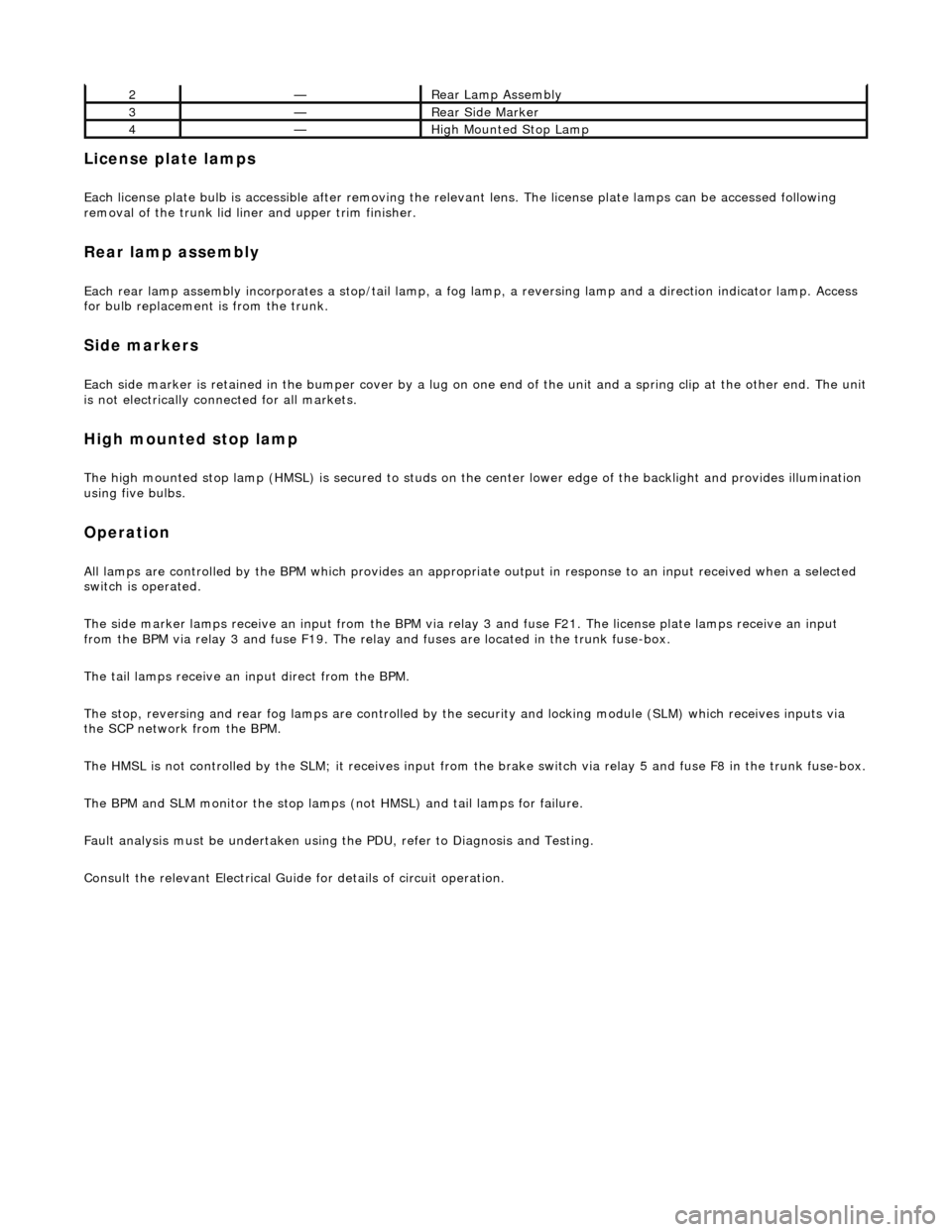
2—Rear Lamp Assembly
3—Rear Side Marker
4—High Mounted Stop Lamp
Page 1926 of 2490
Exterior Lighting - Front Fog Lamp
Removal and Installation
Removal
Installation
1.
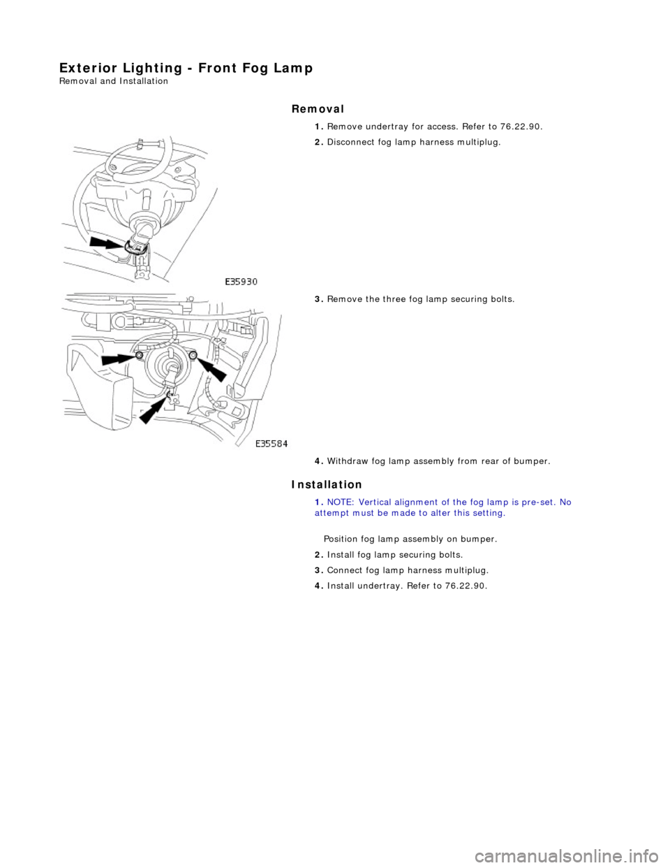
Remove undertray for ac cess. Refer to 76.22.90.
2. Disconnect fog lamp harness multiplug.
3. Remove the three fog la mp securing bolts.
4. Withdraw fog lamp assembly from rear of bumper.
1. NOTE: Vertical alignment of the fog lamp is pre-set. No
attempt must be made to alter this setting.
Position fog lamp assembly on bumper.
2. Install fog lamp securing bolts.
3. Connect fog lamp harness multiplug.
4. Install undertray. Refer to 76.22.90.